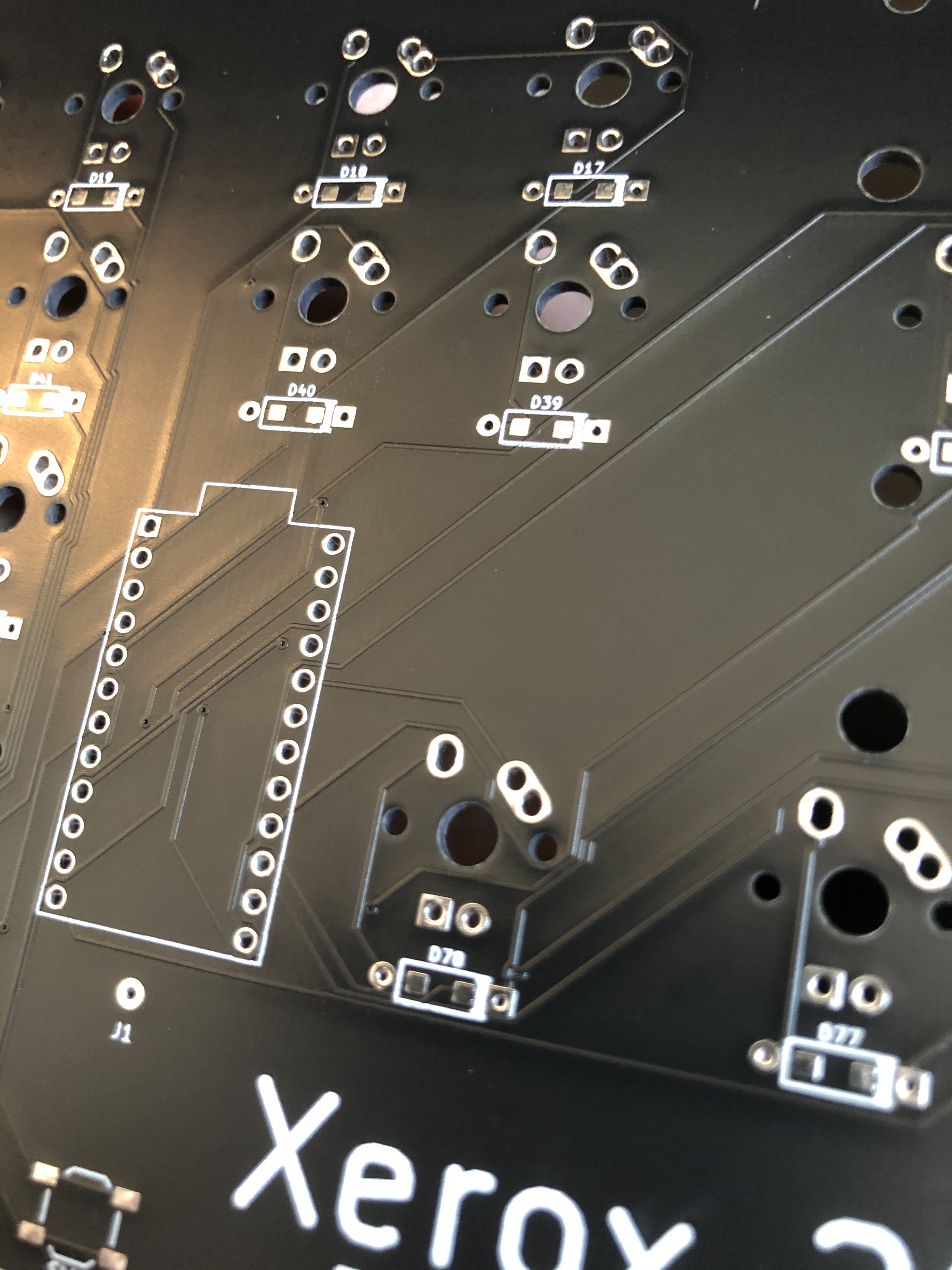
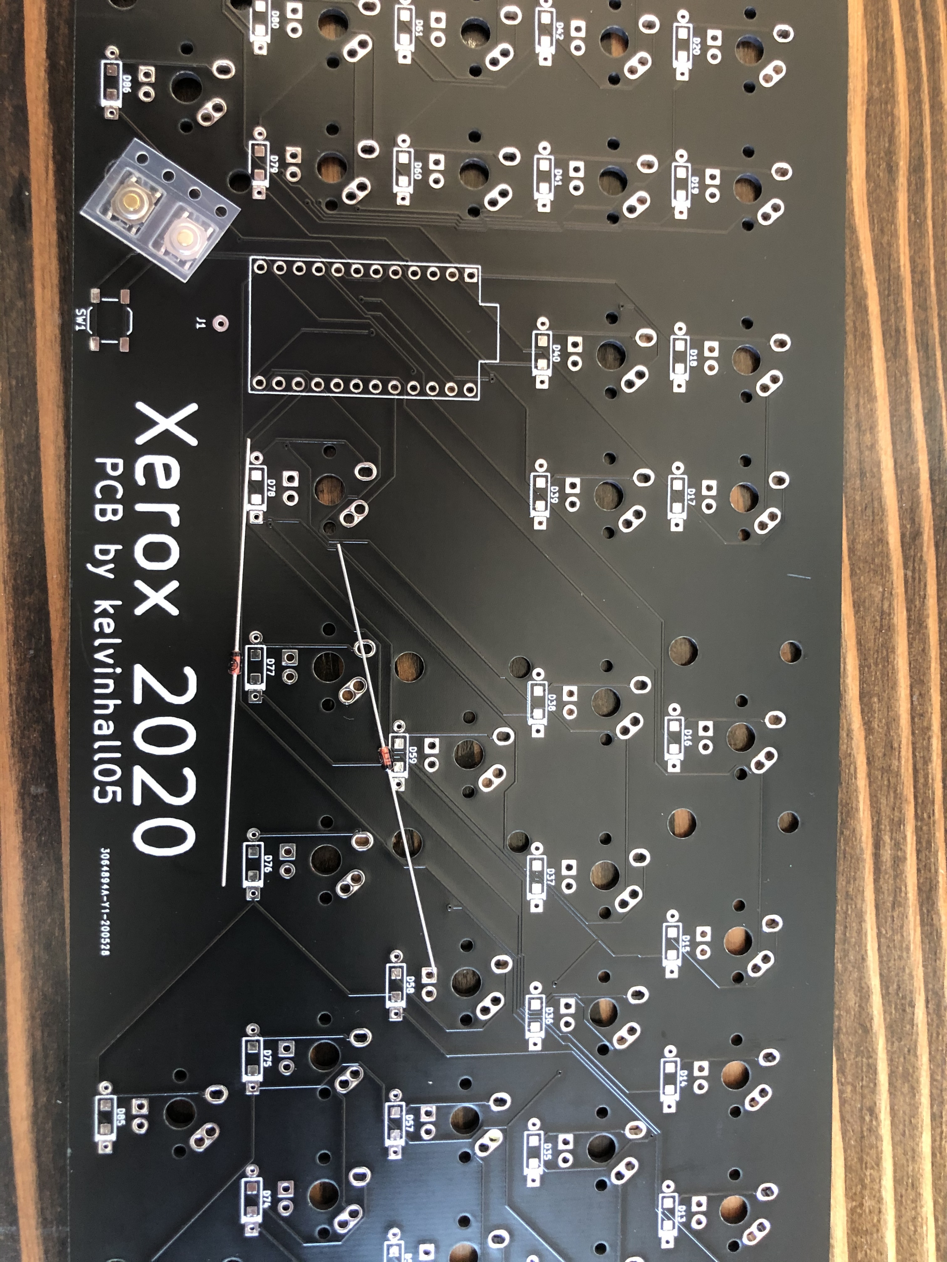
Ok who can tell me which way these little bastards go? Also, does the orientation of the reset button matter?
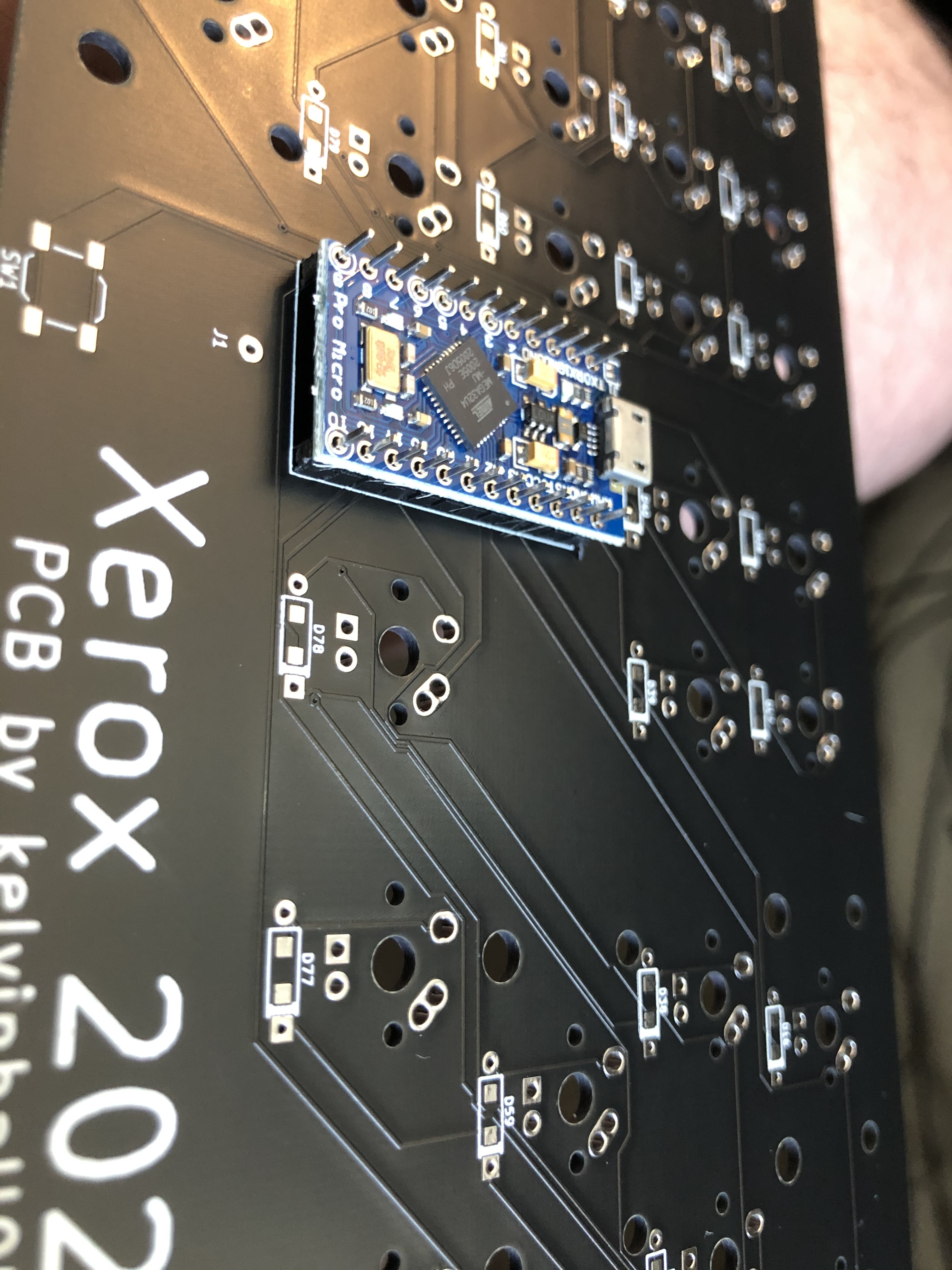
Also, does this pro micro go up or down?
Ok who can tell me which way these little bastards go? Also, does the orientation of the reset button matter?
Also, does this pro micro go up or down?
I assume black goes towards the square hole?
I would actually guess the opposite, but the only way to really be sure would be ask whoever made the PCB, same with pro micro question. Button shouldn’t matter.
The black stripe on the diode should always face the white stripe/square pad on the PCB.
Pro Micro should be smooth side down, component side up the way you’ve got it in the photo.
The reset switch orientation doesn’t matter.
The track on the round home is directly connected to one of the switch holes.
The track on the square hole goes to the mcu.
So i’d guess that the black part of the diode would go on the square hole.
But to be sure a schematic and pcb layout would help confirm that.
Always is a strong statement, you never know when people are going to use their own dumb conventions. I guess I was wrong though, it’s been a long time since I worked with through hole components.
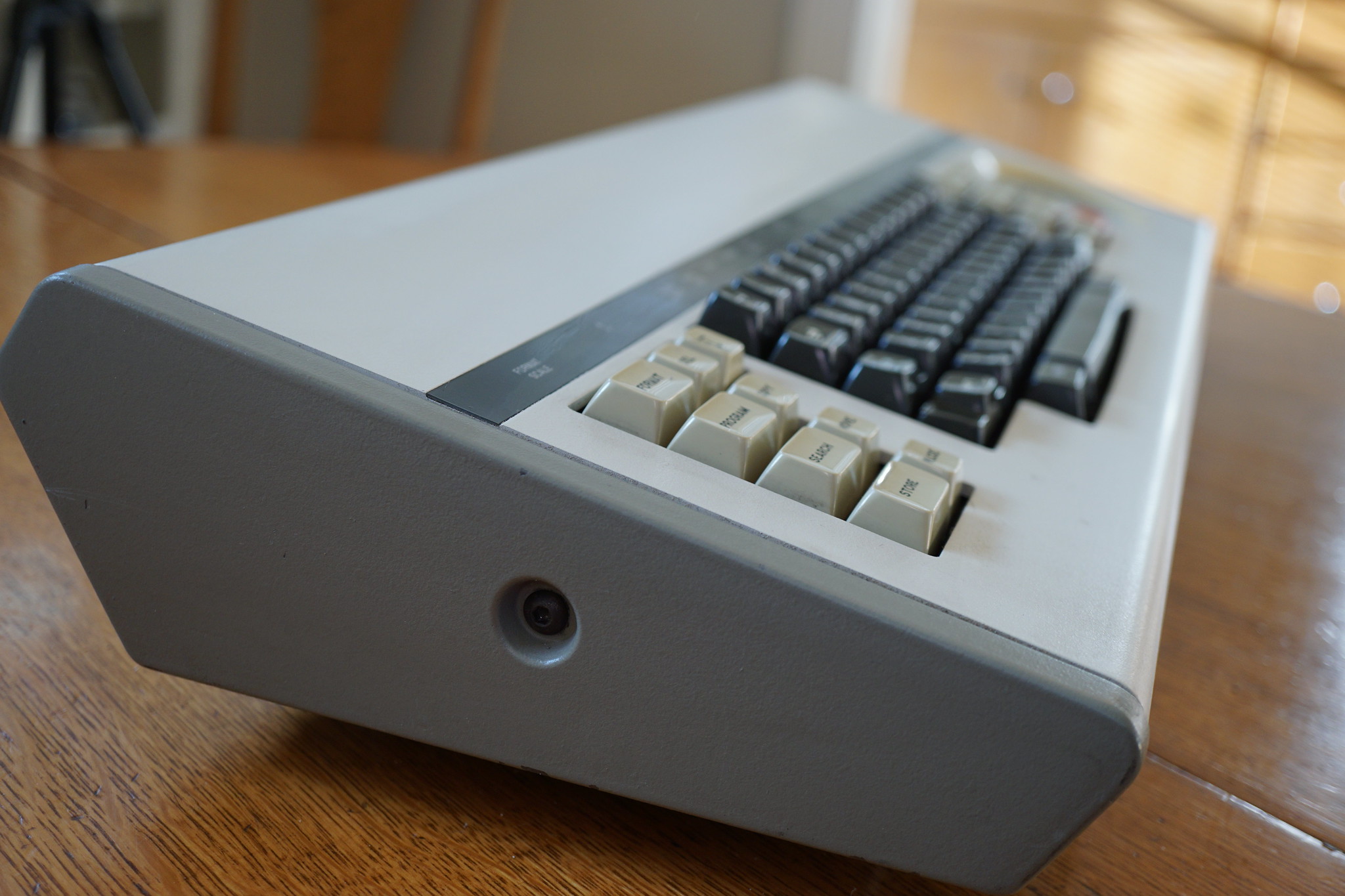
Oh yeah. She’s up and running baby. Follow my build log here: Xerox Custom Build - deskthority
Great!
Glad to see it work 
Very interesting project and very good build log  , I’ll follow it for sure.
Man, you are making such a big boi 
I know, it’s a bit of a monster. There will be other projects besides this one, many equally ludicrous 
I can’t wait