Hi, I'm jshufelt

Would be cool if AirPod Pro could be re-configured to enhance keyboard sound with settings like:

( ) Snare Drum
(x) Bongo Drum
( ) Kick Drum

3 Likes

Build #33: HBCP

In previous build logs, I’ve noted my love for the 1800 layout and its variations. If I were to tabulate the time I’ve spent with various boards as my daily drivers, the bulk of that time would have been spent with the 1800-layout kbd19x (Build #11) and the hybrid 1800/65 southpaw layout EXT65 (Build #29). I’m happy to build just about any board, but when it comes to using one, I find I’d rather err on the side of more keys than more QMK layers. Perhaps remembering all of those Emacs keybindings for a few
decades used up all of my long-term memory?

I’m not sure exactly when I stumbled across the IC for the HBCP by Hineybush, but as soon as I saw it, I knew I had to get my hands on one. The IC had a pretty long gestation period, but the GB ran in September 2019, production was quick, and fulfillment is in progress right now. Often when I receive a build kit, it’ll sit on my shelf for a while as I build up the fortitude to lube yet another batch of switches.
But not this one. Will the HBCP clear the high bar to enter my daily driver rotation? Let’s find out.

Let’s start with the PCB. The microcontroller on the HBCP PCB is an AT90USB1286, and the PCB
supports USB-C. The PCB supports a few different choices for layout: split left shift, split numpad keys, and 6.25u vs 7u bottom row.

Flipping it over to the top side, we see a couple of interesting features. First, there is a preinstalled connector cable for a daughterboard that hosts the NCS indicator lights. Second, the reset button is on the top of the PCB, not the bottom where it usually resides.

Right after shipment, a problem was discovered with the production PCB - hitting the 6 key on the numpad resulted in all of the keys in that column registering keypresses. The fix turned out to be straightforward - cut a specific trace on the PCB in two places. I hadn’t done this before, but it’s trivial; get a box cutter, Xacto knife, or razor blade, and scrape the tip of the blade back and forth across the trace until you feel that you’ve severed the trace. You can test the numpad 6 with Switch Hitter, before and after, to confirm that you’ve successfully cut the trace. The following photo shows the two locations where you need to sever the trace.

If you’re still freaked out by doing this, let me give you another analogy. You know those gift cards or lottery tickets where you have to scratch off that stuff to reveal the code or prize? It’s like that, but instead of scratching off an area, you’re scratching off a line.

Cutting that trace also severs connectivity to three of the underglow RGBs. If you want to restore that functionality, you’ll need to solder a jumper on the PCB, but since my case was aluminum and I don’t need or want RGB, I didn’t bother.

Before we go further, we’re going to want to flash the PCB so we can bind RESET to something. I downloaded the HBCP hex from the caniusevia website, flashed it with QMK Toolbox (remember, AT90USB1286 controller!), fired up VIA and changed some bindings (super easy to change layouts, which I appreciate - still can’t do mod tap yet, but VIA is getting closer and closer to something I could
regularly use). But I’m sold on VIA for at least the basic pre-build config to get RESET where I want it, my QMK setup is complicated, and I don’t always want to take the time at the beginning of the build to make a custom hex just so I can get RESET functionality.

Next up: stab modding. That all looks pretty standard. Hey, wait, what’s that bit of green PCB material?

The HBCP PCB is one of Hiney’s “thinboi” PCBs, 1.2mm in thickness instead of the usual 1.6mm to give additional flex (at least if you choose a softer plate material). However, stab housings are designed to fit a 1.6mm thick PCB, so they will wobble if installed in the usual way on a 1.2mm PCB. Enter the stab spacers - little pieces of FR4 with cutouts for the clip hole and screw hole of a stab housing. Once you’ve modded and lubed your stabs to your satisfaction, you break the stab spacer sheet into individual stab spacers along the scoring lines.

From the top side of the PCB, nothing looks different about the stab installation.

From the bottom, however, we can see the stab spacers in action. Hiney provided a video showing how to install these - the “trick” is to slide the stab spacer under the stab clip first before seating the stab housing into place. Looking at this next photo, it looks like the left spacer is not quite as well wedged under the housing clip as the one on the right - but as they say in basketball, no harm, no foul.

Here’s all six stab spacer pairs, after installation. Note that a couple of the stab spacers pass over surface mounted components on the PCB - the spacers are flexible enough that you’ll be able to bend them over the components, although it does make the stab installation a bit more involved than usual. A couple of the stab spacers took me a few tries to get seated properly. As with most issues in a build, patience and persistence are your friends.

Everything looks good from the top side.

Time to take the case part so we can get to the plate. This HBCP is black-anodized aluminum, with a matte-finished brass plate, and the hbcp logo engraved on the interior left side of the base weight. Note the full-size “Hiney rag” that came with the kit, for protecting the case and wiping the case down. I appreciate these kinds of details.

The underside shows the base weight, clean and simple with no exterior engravings.

Show off those curves.

Might as well install those bumpons while we’re here. The bumpon cutouts are a bit deeper than most boards I’ve built, so the board will sit closer to the desk or deskmat with bumpons installed.

After removing the case screws, we can get a good look at the case interior. Five screws hold the weight in place. Also note the slot cutouts along the edge, to properly align the case top and bottom - another detail I appreciate.

Moving our attention to the case top, the brass plate is top-mounted, with a number of relief cuts, so we won’t be doing any Sorbo strut mods here (parenthetical aside - I feel like more and more of my recent builds are using plates with relief cuts? Just an observation.)

Removing the plate screws, we’re left with the top, and the preinstalled indicator light daughterboard.

Sometimes I wish I had a comfortable seat on the WKL train. Do you see an issue here?

It turns out there was an oversight in the plate design - if you’re doing a 6.25u bottom row layout, the cutout for the spacebar’s left stab housing isn’t deep enough on the bottom edge, so the plate can’t seat properly. After thinking about this for a bit, I figured there were three options:

  • Dremel the plate to make room. It’s a nice-looking plate, though, and I don’t want to scuff it up.
  • Switch to 7u bottom-row, for which the cutouts are correct. No Win key, though?
  • File the left stab housing into conformance with the plate.

Option number three it is! With a needle file and a bit of patient filing, you can make it work. I found it easiest to lightly rest the flat side of the file on the screw housing while using the edge of the file to start a groove - this will file away a bit of the screw housing surface, but that’s not really an issue. Once the groove is started, it’s just a matter of keeping the file level and straight while you deepen the groove.

And with that mod completed, the left space stab “clips” into the plate.

With a nice clean fit between the PCB, the stabs, and the plate, the switches were seated in the plate and PCB, and soldered into place. This is a good time to note another nice feature of the HBCP - the PCB reset button is on the top, and is accessible through a relief cut next to the right shift key. I can’t count the number of times I’ve forgotten to flash a QMK firmware with RESET bound to something I can remember before assembling the keyboard, and it invariably happens on boards where there is no access hole in the case for the reset switch, so it’s nice to know that if I forget again, I can just pop off the right shift key to get to it. Can we please have this feature on every PCB and plate from now on?

And, yeah, it’s some kind of Murphy’s Law for the build - the one time I remember to flash a new hex and put RESET somewhere useful, I didn’t need to bother. Sigh.

Now back to that daughterboard. This is the point in the build where you need to connect the daughterboard to the PCB, and that part’s easy enough if you hold the PCB vertically next to the case top while you insert the connector into the daughterboard socket.

Before we go further, let’s jump back in time a bit, and take a closer look at the positioning of the daughterboard. It’s bounded on one side by the port for the USB-C connector, and, when fully assembled, by switches and keycaps on the other three sides. Also, note the recessed area for the plate screw; the HBCP comes with O-rings, which will sit in those recessed areas for a top-mount setup for the plate.

As you may have guessed, things are about to get interesting again. Your mission, should you choose to accept it, is to place O-rings in the recessed screw holes for the plate, and, while screwing in the plate, make sure that the extra connector wiring for the daughterboard is properly tucked into that little bit of space allotted for it. On the first couple of attempts, I found that the wires were getting pinched by the case top when I tried to seat the plate, but it was difficult to position the top to work on it without O-rings falling out of place. Once I realized what the space constraints were, I was able to “bend” the wires to keep them from getting pinched. You can see a couple of them peeking out here, but they’re not being pinched or preventing the plate from seating properly in the case top.

Finally!

With keycaps, what’s the verdict? This is a heavy boi, with tight clearances between the PCB and the case, and that’s reflected in the sound - deep, bassy, with as much thock as clack. Some of that might be due to the use of 205g0 on the switches instead of my usual 3204, but I think most of it is heft of the board and the O-ring top mount. Part of me wants to try to squeeze a couple more percent of sound improvement out of it with a thin layer of Sorbothane, but honestly, it really doesn’t need it. Sitting on a deskmat, the sound is wonderful.

Lessons learned

  • Patience! Between trace cutting, stab filing, and wire placement, this build had a few more challenges than the usual slap-it-together-60, but none of these are big issues - just take your time.
  • Every GB has its own twists and turns, and you always end up in a slightly different place than you imagined when you started. This was my first keyboard GB with Hiney, and hopefully not the last; progress communication during the GB, and support for issues after the GB, was A+.
  • I need to remember the stab filing trick - I’ve gone with plate filing in the past to address cutout issues, but this was easier (and if I screw it up on some future build, it’s cheaper to replace a stab than a plate!)
  • I tried 205g0 on tactiles for the first time (I’ve used it on linears before). As always with 205g0, you have to be careful to apply a thin coat, but you can get an even more buttery feel than 3204, if that’s your thing.
  • Do I really understand the variables in board sound? Every time I think I’ve started to get a handle on it, a board comes along and messes with me. This board sounds significantly better than my expectations (which were relatively high to begin with, thanks to build videos like this one), and despite my commentary earlier, I’m not entirely sure I understand why.

But I’m not complaining. Welcome to the rotation!

The HBCP looks like this in real life.

The HBCP doesn’t look like this in real life, unless I leave my Hue lights set to purple. But maybe I should.

Specifications

case: Hineybush HBCP
- black anodized aluminum
case dampening: top-mount O-rings
PCB: Hineybush HBCP (AT90USB1286)
plate: matte finish brass
plate/PCB dampening: n/a (relief cuts)
stabilizers: GMK PCB screw-in
- 1x6.25u, 5x2u
stabilizer mods:
- clipped and lubed with SuperLube
- HBCP stab spacers on screws/tabs
- left spacebar stab filed for 6.25u plate fit
switches: 98x 78g V2 Zealios
switch mods:
- springs tub-lubed with Krytox GPL 104
- stems hand-lubed with Krytox GPL 205g0
- no housing lube
keycaps: GMK Oblivion V2
- monochrome base
HxWxD (without caps or feet): 1.19" x 14.94" x 5.44"
HxWxD (without caps): 1.25" x 14.94" x 5.44"
HxWxD: 1.5" x 14.94" x 5.44"
assembled weight: 3.07 kg (6.76 lb)
13 Likes

Beautiful build as usual! Pretty neat way Hiney came up with for installing the stabilizers on his thin PCBs.

2 Likes

Thank you for this build log, very nice 1800 keyboard !
Too bad for the minor mistake on the PCB, looks like shit also happens with the bests.

I heard that brass and steel for plate material were producing higher pitched sound than POM or even aluminum.
You said it was bassy on this keyboard, like if the PCB was acting as a speaker subwoofer membrane due to lack of space beetween it and the bottom case to let air freely escape.
This is a very interesting theory that you have :wink:

1 Like

All roads lead back to proper recording and frequency analysis. If I had an unlimited budget and/or the right friends, I’d record typing tests in an anechoic chamber, do some DSP to get the power spectrum, and then try to relate those with attributes we believe are relevant to the sound.

Don’t expect a log for that project any time soon…

4 Likes

Build #34: Austin

I still have far too many work surfaces in my house that don’t have a CP-style board. So, how about we keep the big board party going? Hot on the heels of the HBCP, the Austin from Drift Mechanics arrived
on my doorstep, and although my build backlog keeps growing, I couldn’t resist doing this build now as a nice counterpoint to the HBCP.

If you’re a regular reader of these build logs, you know that my tastes run to tactile switches, and generally speaking, I’m fine with assertive tactility (Holy Pandas or 78g V2 Zealios, anyone)? But, after what feels like a lot of builds with loud, heavy, clacky switches, I wanted to dial things back a bit, and I’ve had the impression that a stock Halo Clear might offer a more moderate tactile experience without sacrificing too much of the sound that I enjoy.

So, rather than sacrifice more Halos to the HP gods, I decided to give Halo Clears a shot for this build. To allow for more direct comparison with switches I know well, I used what has become my default tactile lubing approach these days: tub-lubing springs with 104, and stem lubing with 3204. I’ve reached the point where I don’t bother lubing the switch housings; I’ll instead make sure to lube the “rail” around the top of the stem, where the stem makes contact with the housing. With that approach, enough lube gets transferred to take the slightest edge off of the clack without dramatically affecting sound. Let’s get to the build!

The Austin PCB uses an ARM STM32F072, it’s relatively free of swiss cheese, and it offers ESD protection, which is very much appreciated by those of us who live in dry climates, particularly during the winter months. Looking at the top of the PCB, the finish is somewhere between shiny and matte black; enough reflection to see me taking potato pics, but that’s about it. To my eye, the Austin logo is tastefully done here. Note that the PCB also ships in a nice ESD bag, which it’s resting on in this photo.

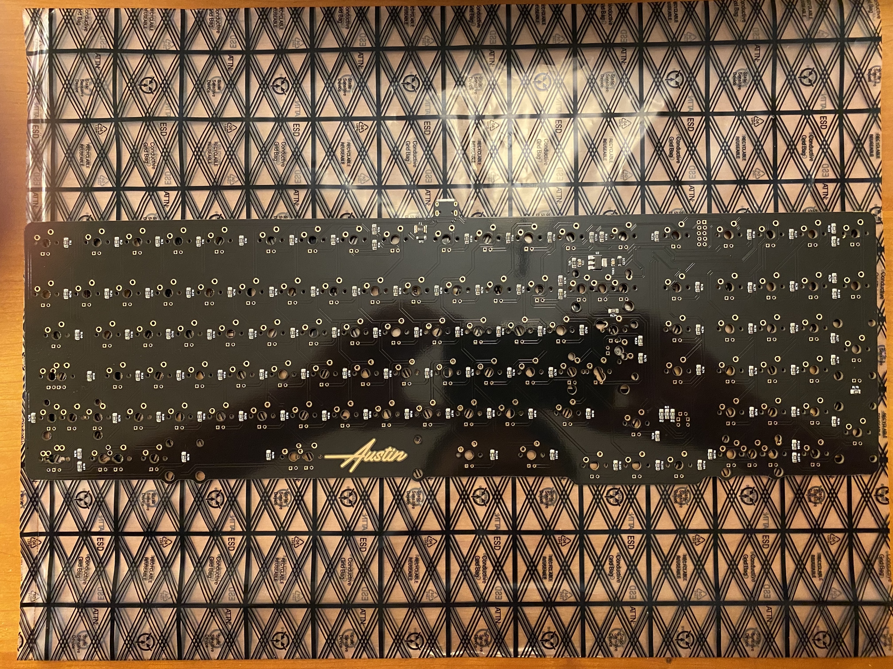
The reset button is located on the underside of the PCB, just above the numpad cluster, not too far from the ARM chip. This means we’ll want to flash the board to our desired keymap before we close up the case.

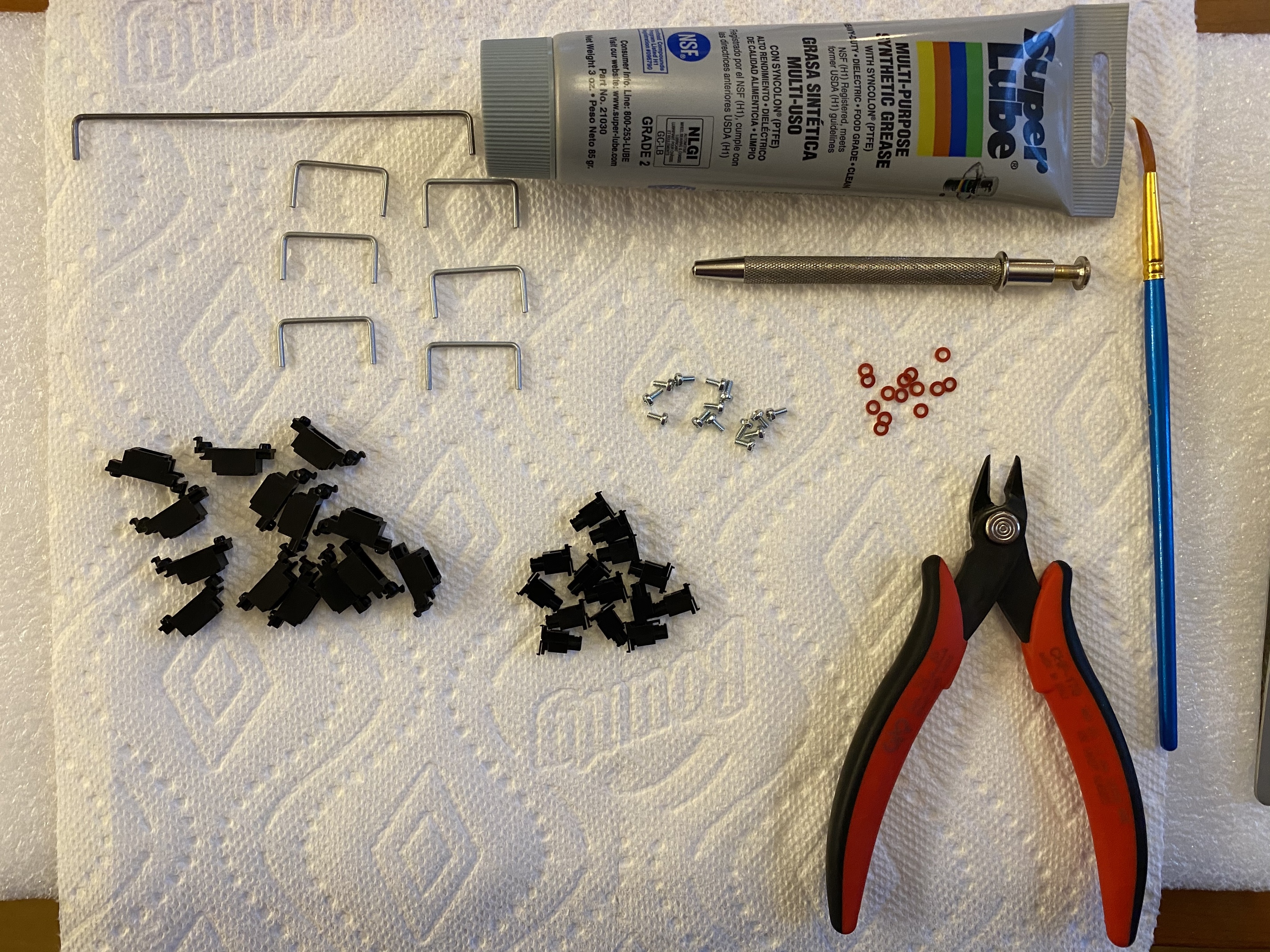
Getting prepped for stab time. Eating into my stash of good GMK screw-in stabs, and pulling out some cloth washers just in case.

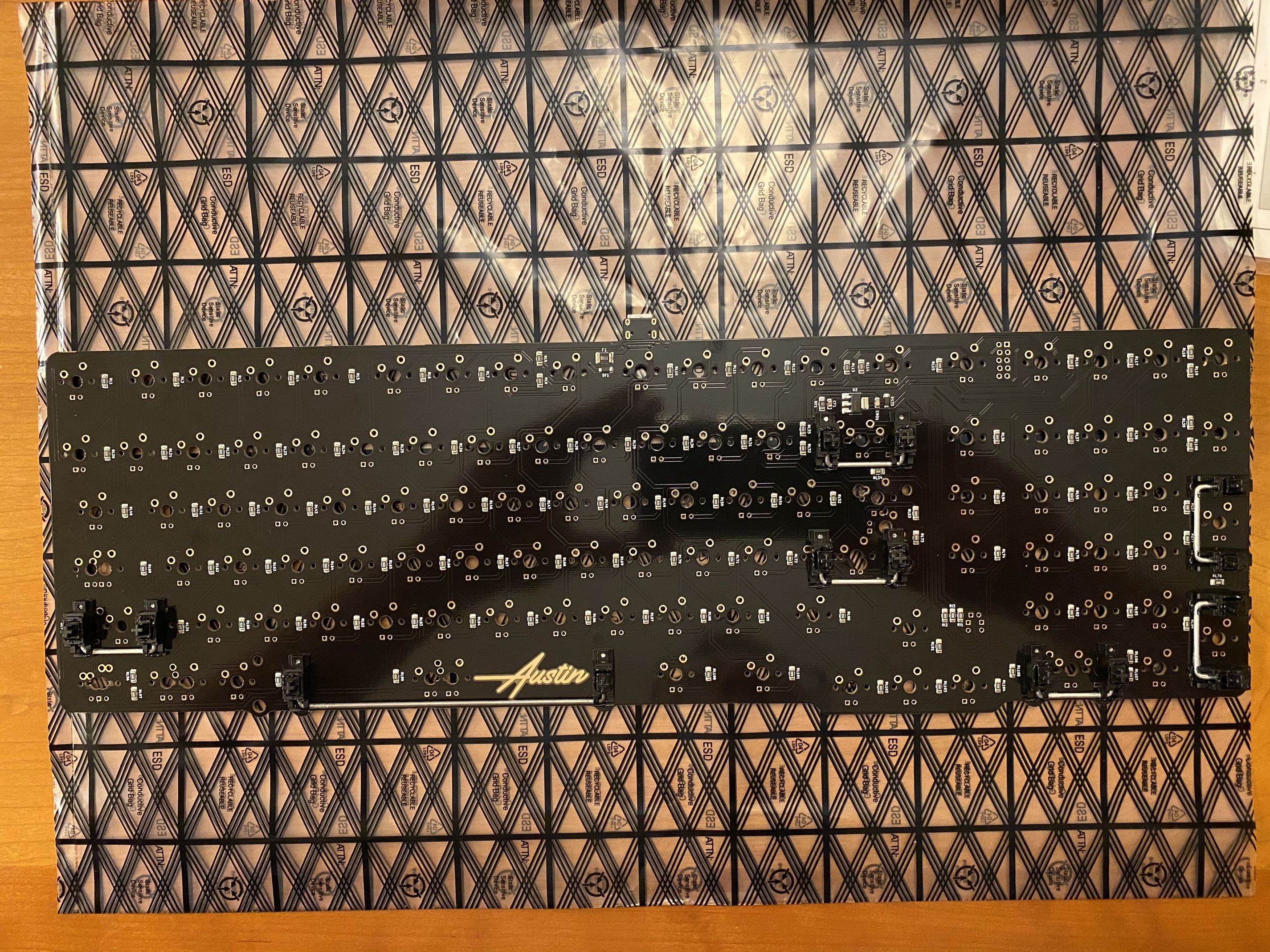
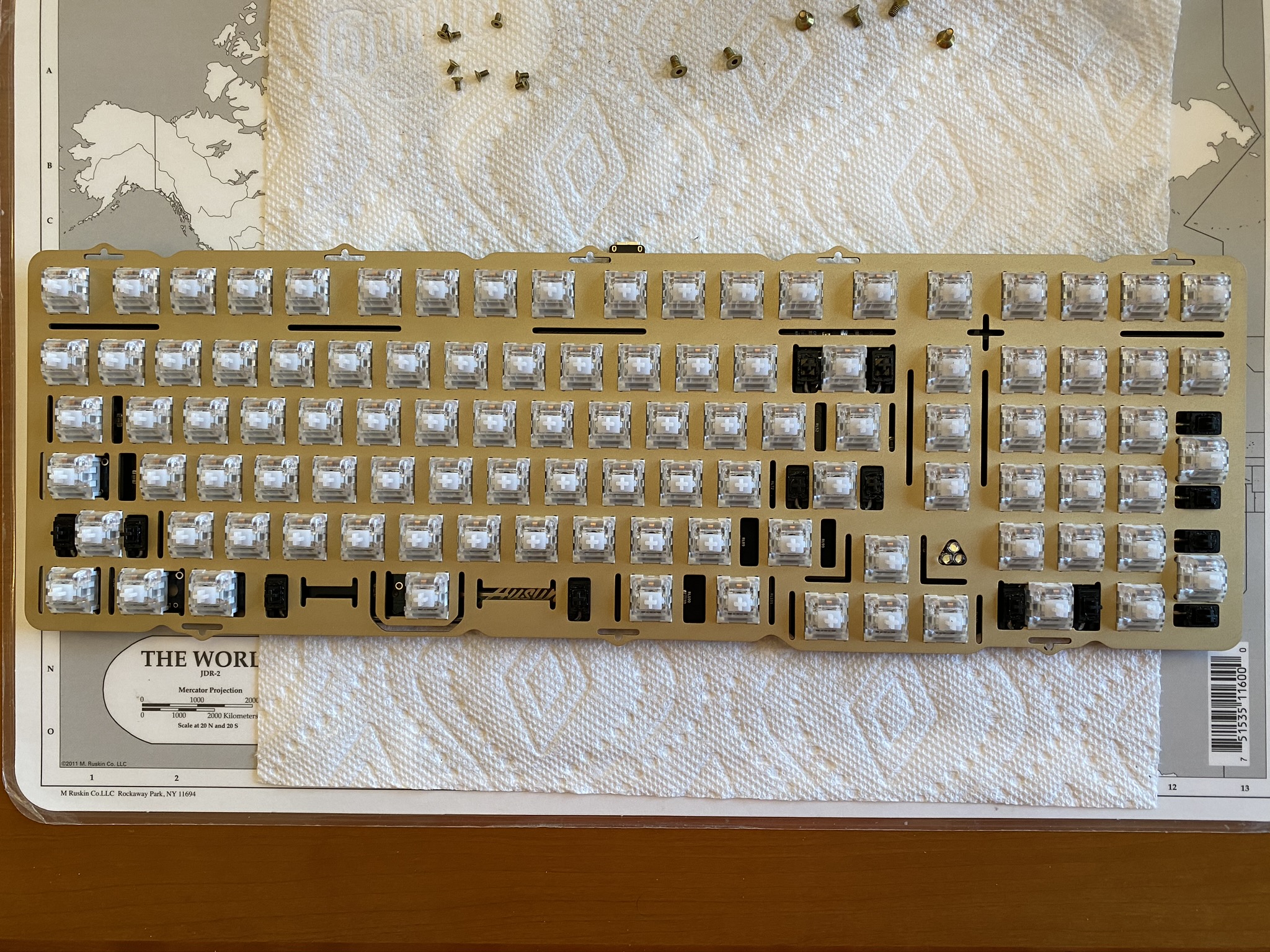
After clipping, lubing, and installing, here’s the top side of the PCB.

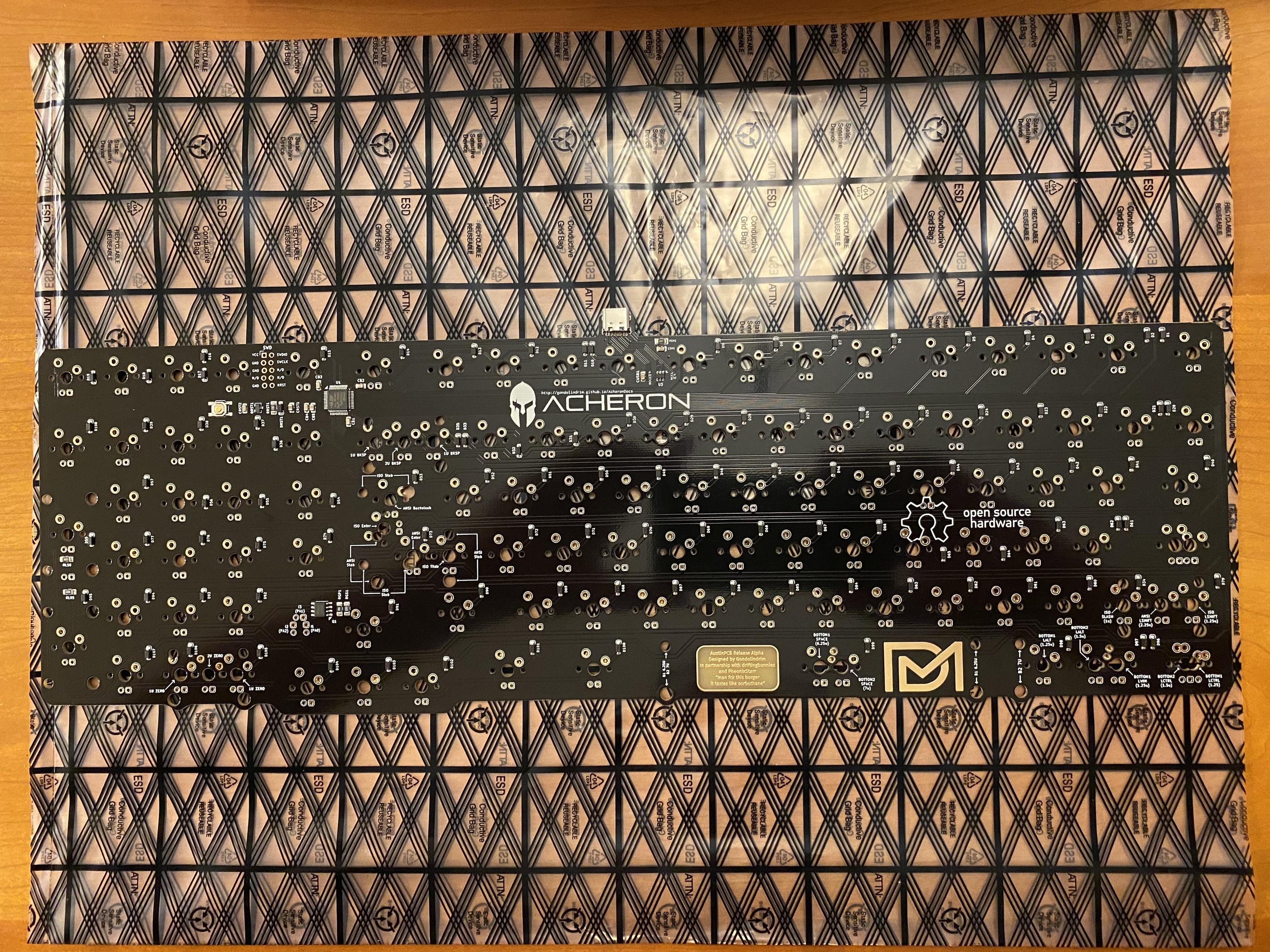
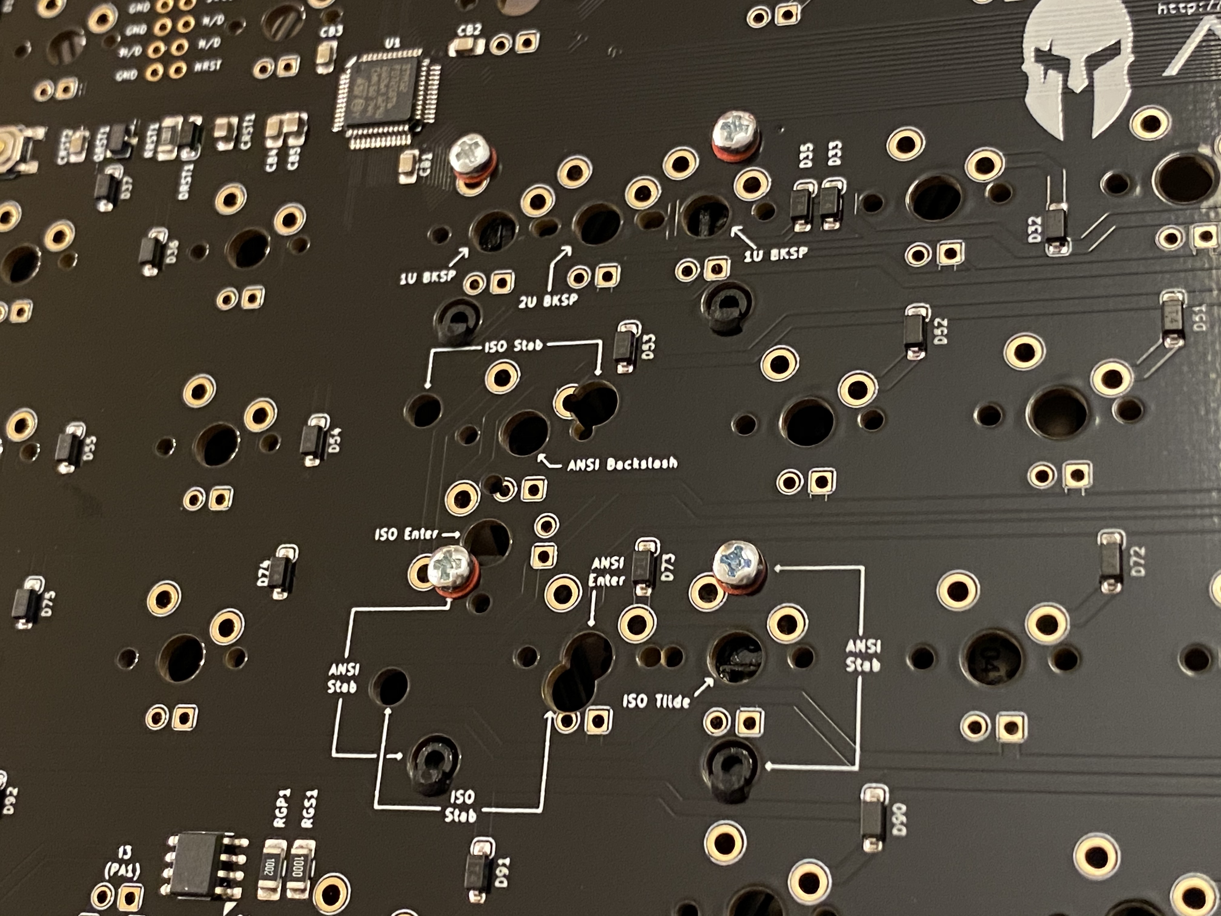
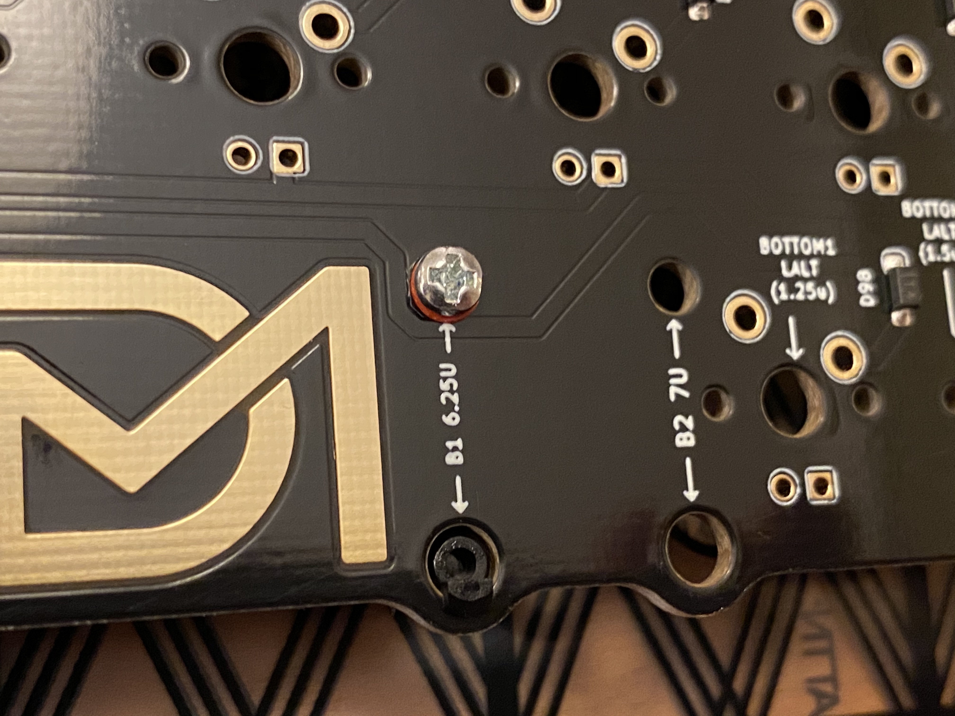
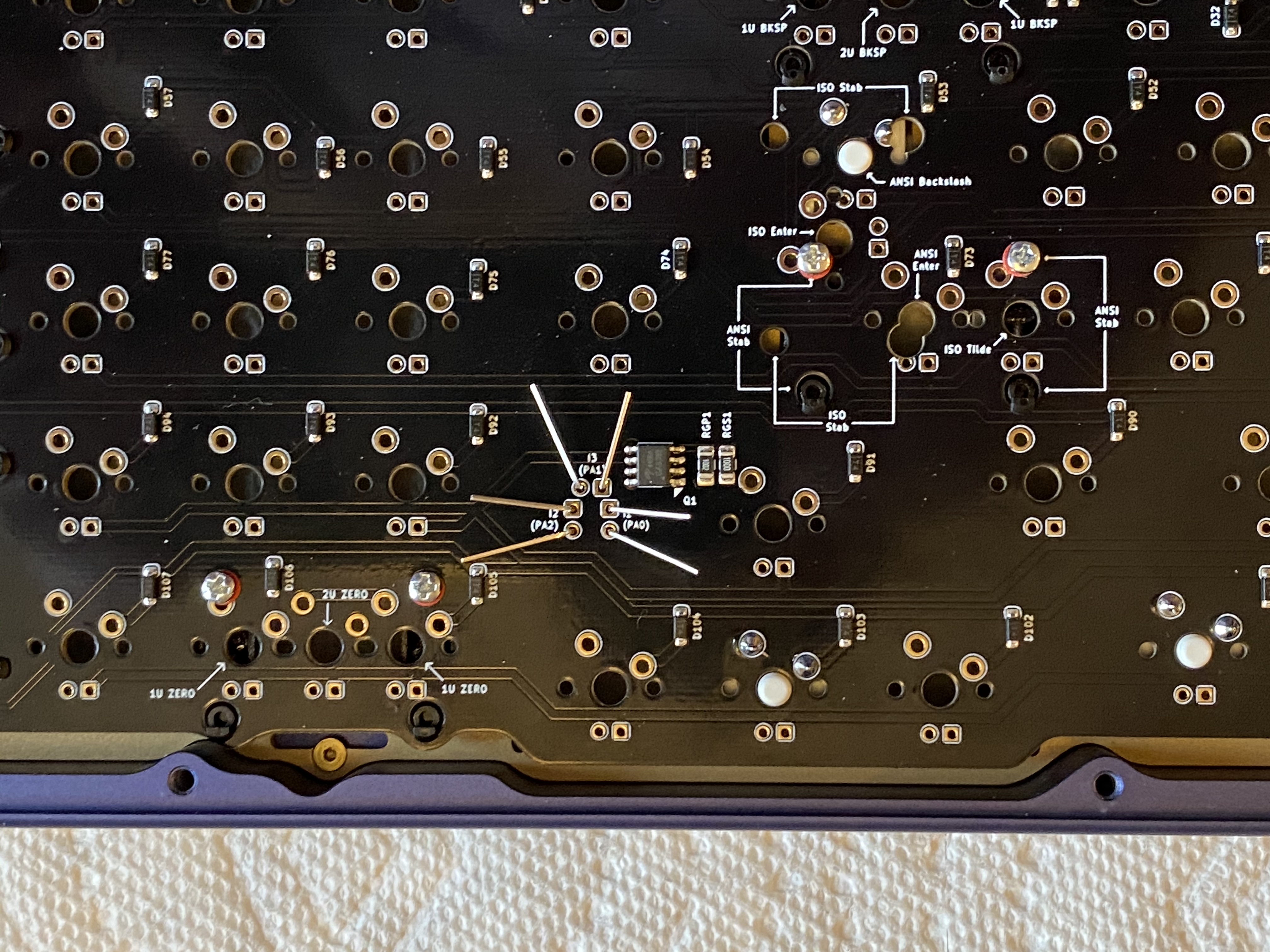
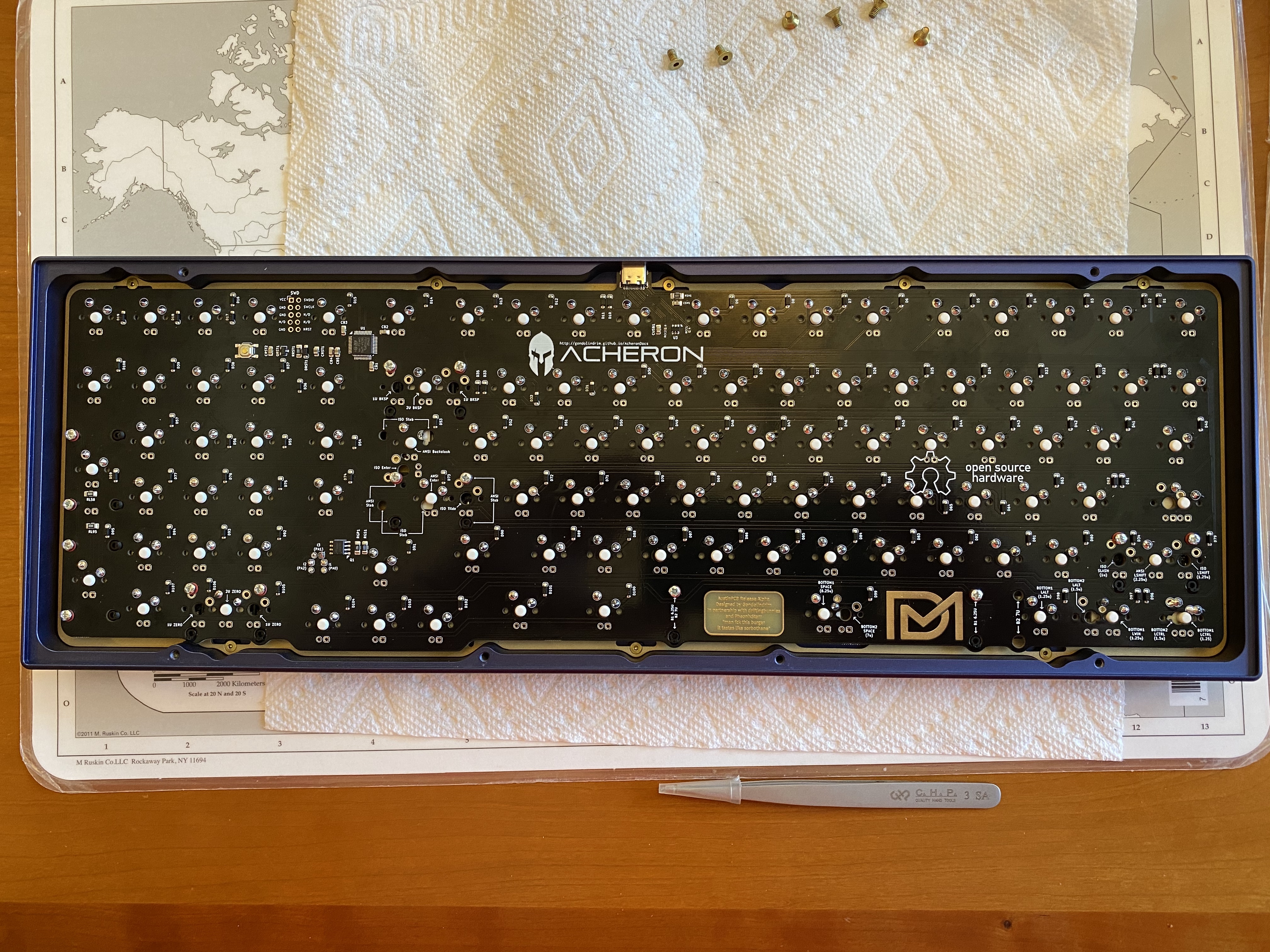
Looking at the underside of the PCB, we get a good look at a nice feature of this PCB - where multiple stab holes are present, text markings tell you which holes correspond to various layouts. For new builders, this can be very helpful, and even for seasoned builders, it’s a convenient touch. I’m somewhat surprised this hasn’t become a more common feature for PCBs that support multiple layouts.

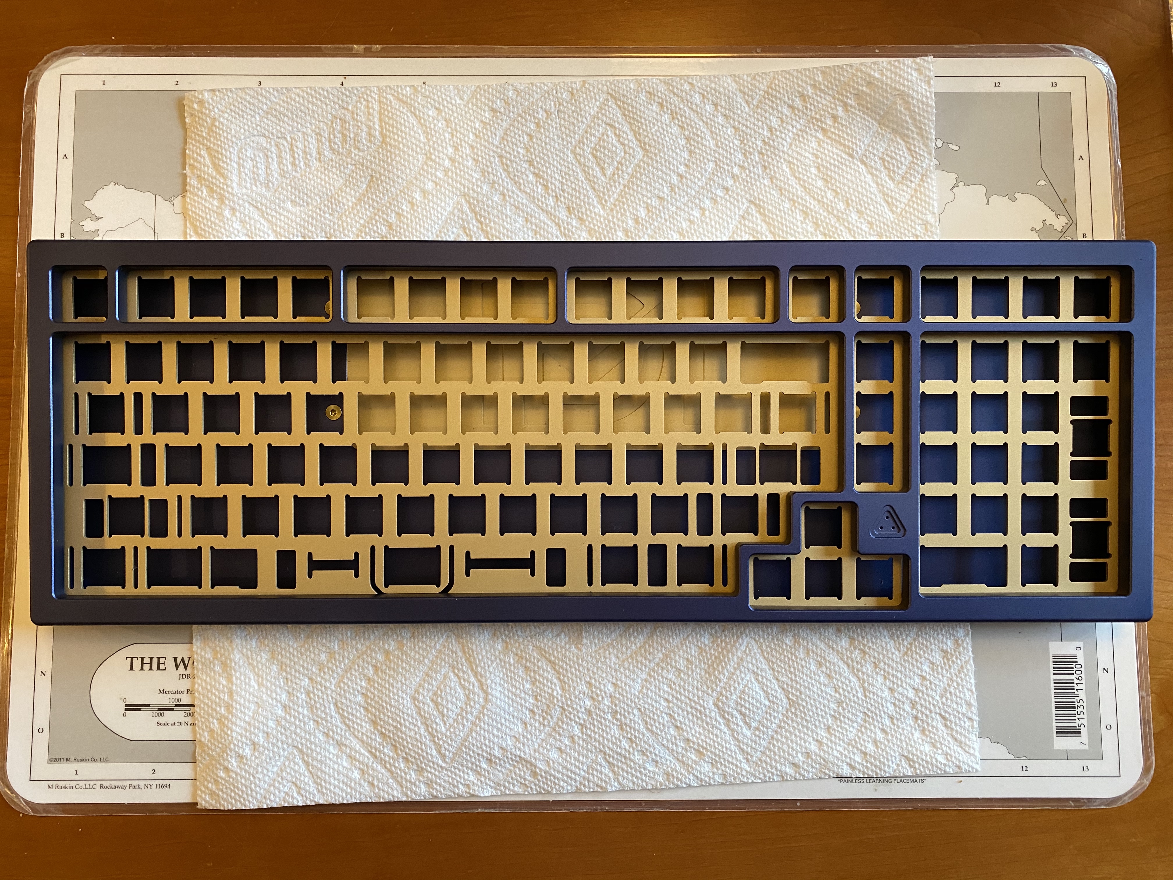
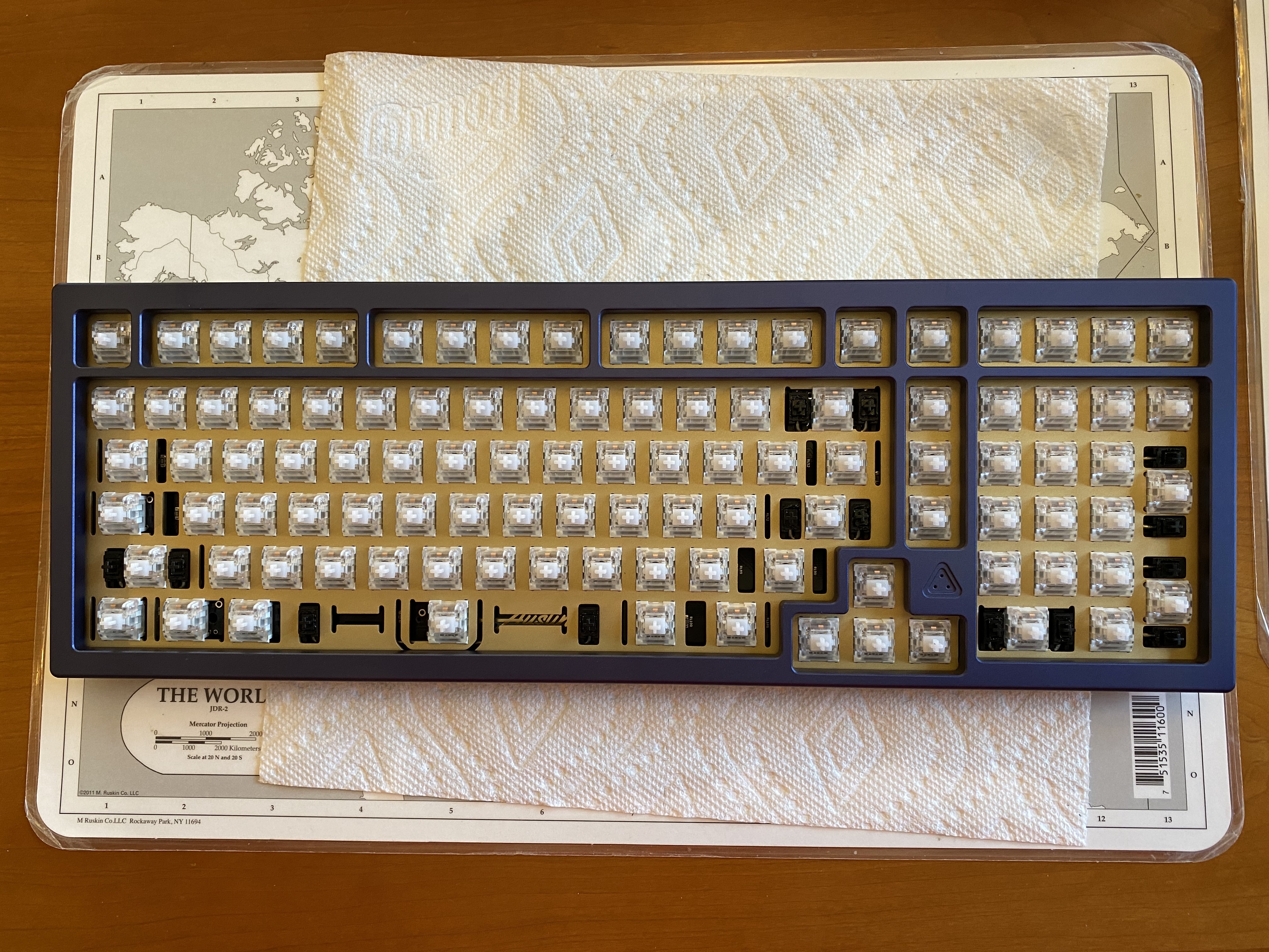
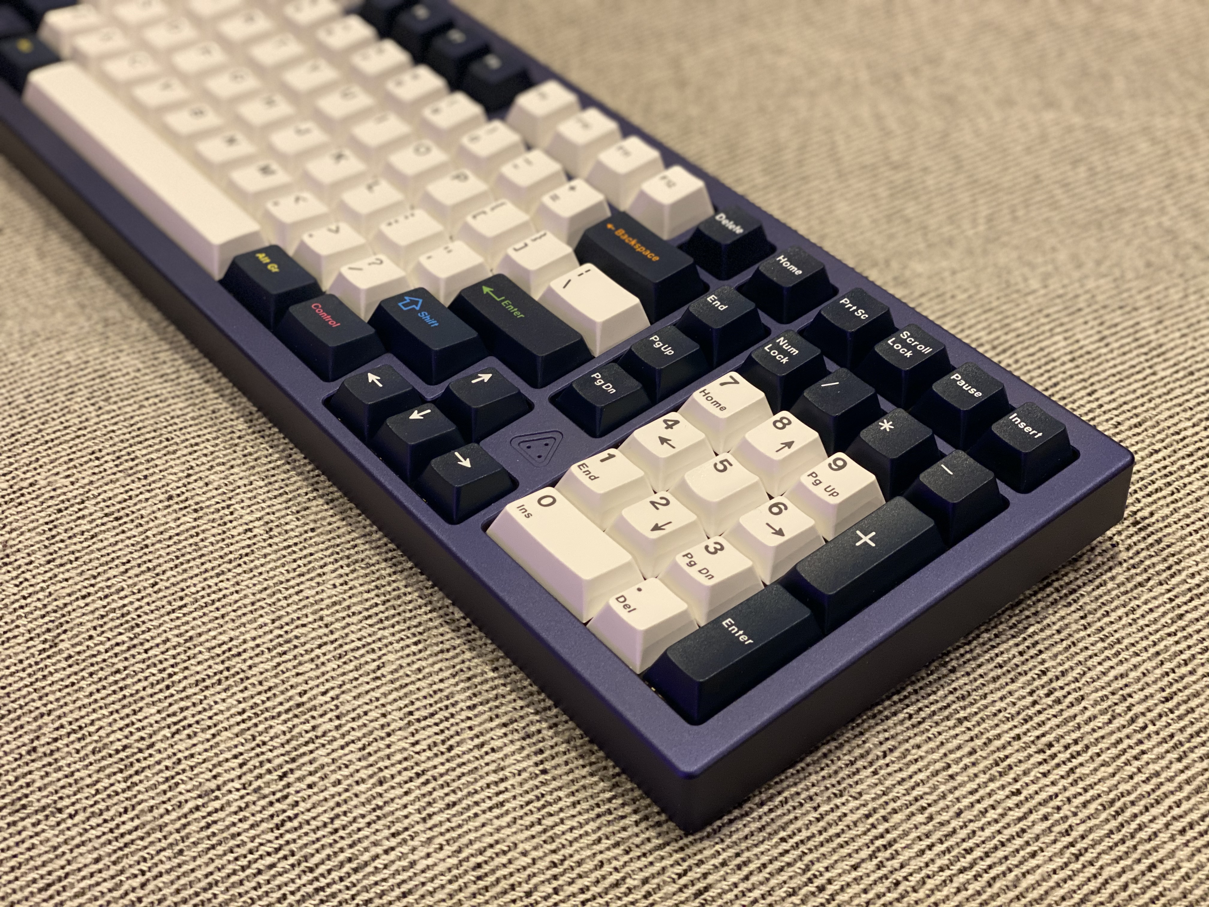
Before we proceed further, let’s take our first good look at the Austin case and the sandblasted brass plate, as well as what is arguably its main distinguishing feature visually and functionally - an additional column of keys between the numpad and the rest of the board. A triangular group of LEDs sits directly under the logo on the top of the case, which has holes to allow light to shine through.

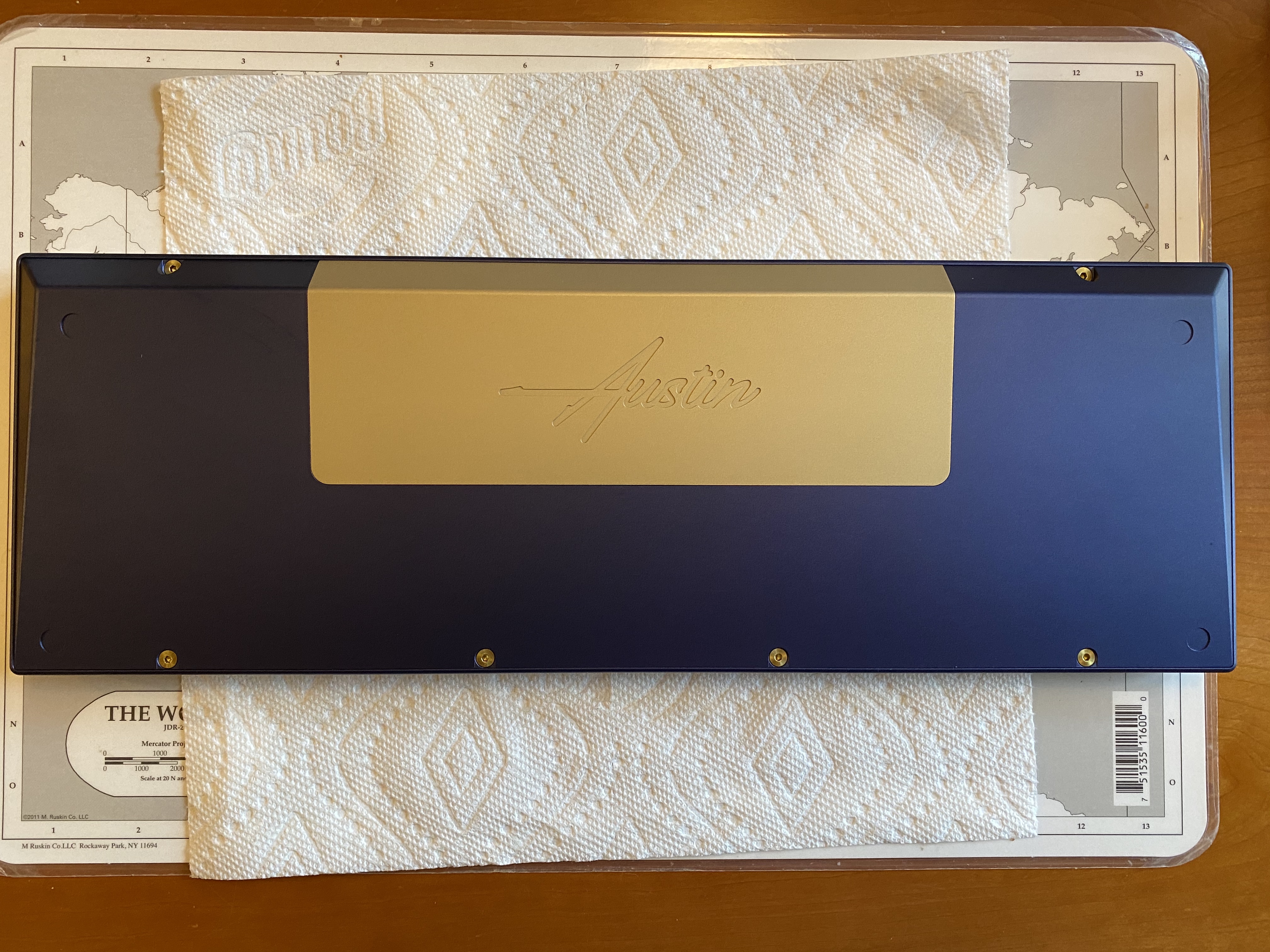
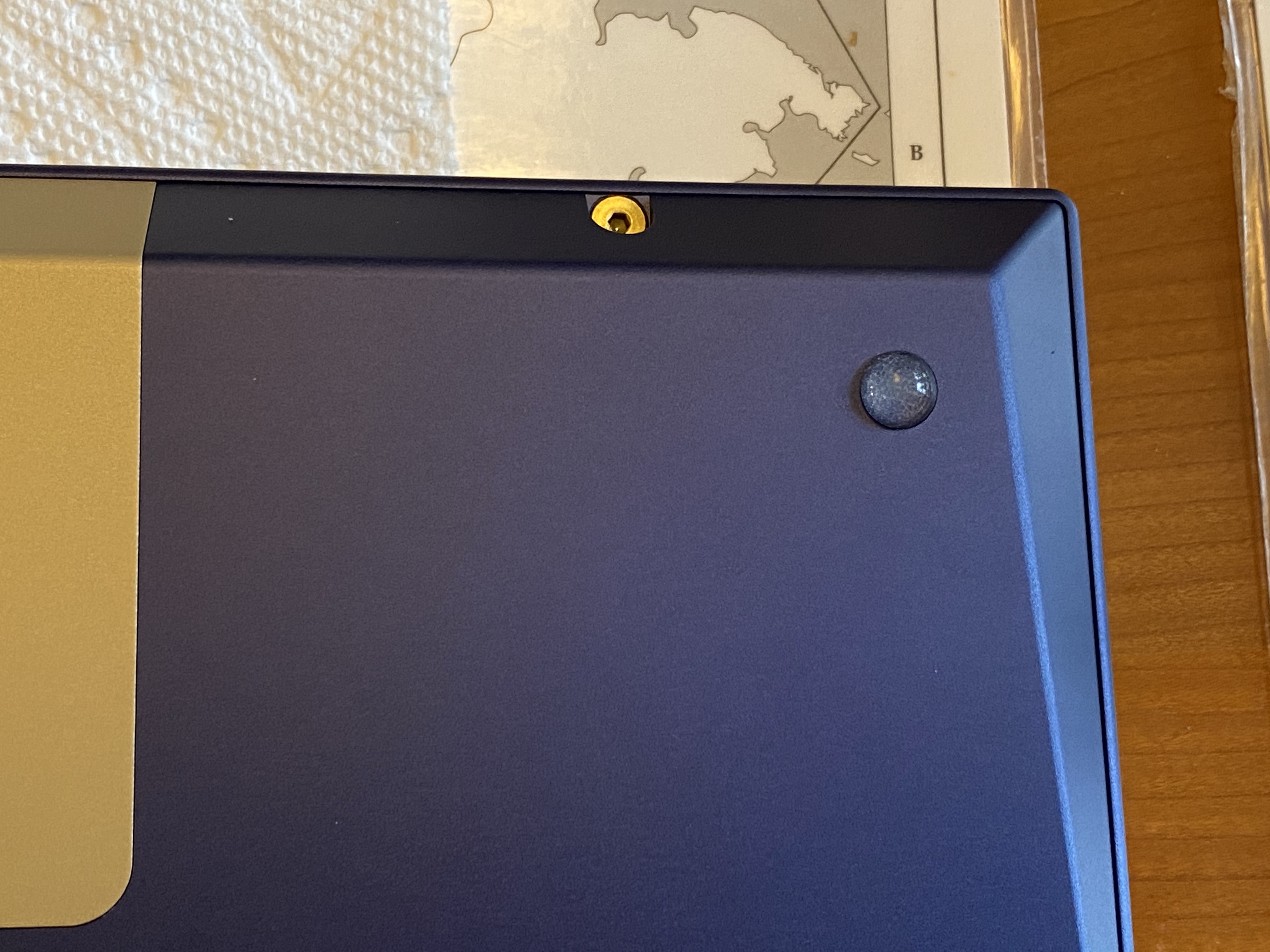
The underside of the case features a brass weight, with engraved Austin branding. The top and bottom of the case are held together by six screws. The finish on the weight and the case is quite good - it’s an A-stock board, and it looks the part.

Bumpon time - nice, snug fit.

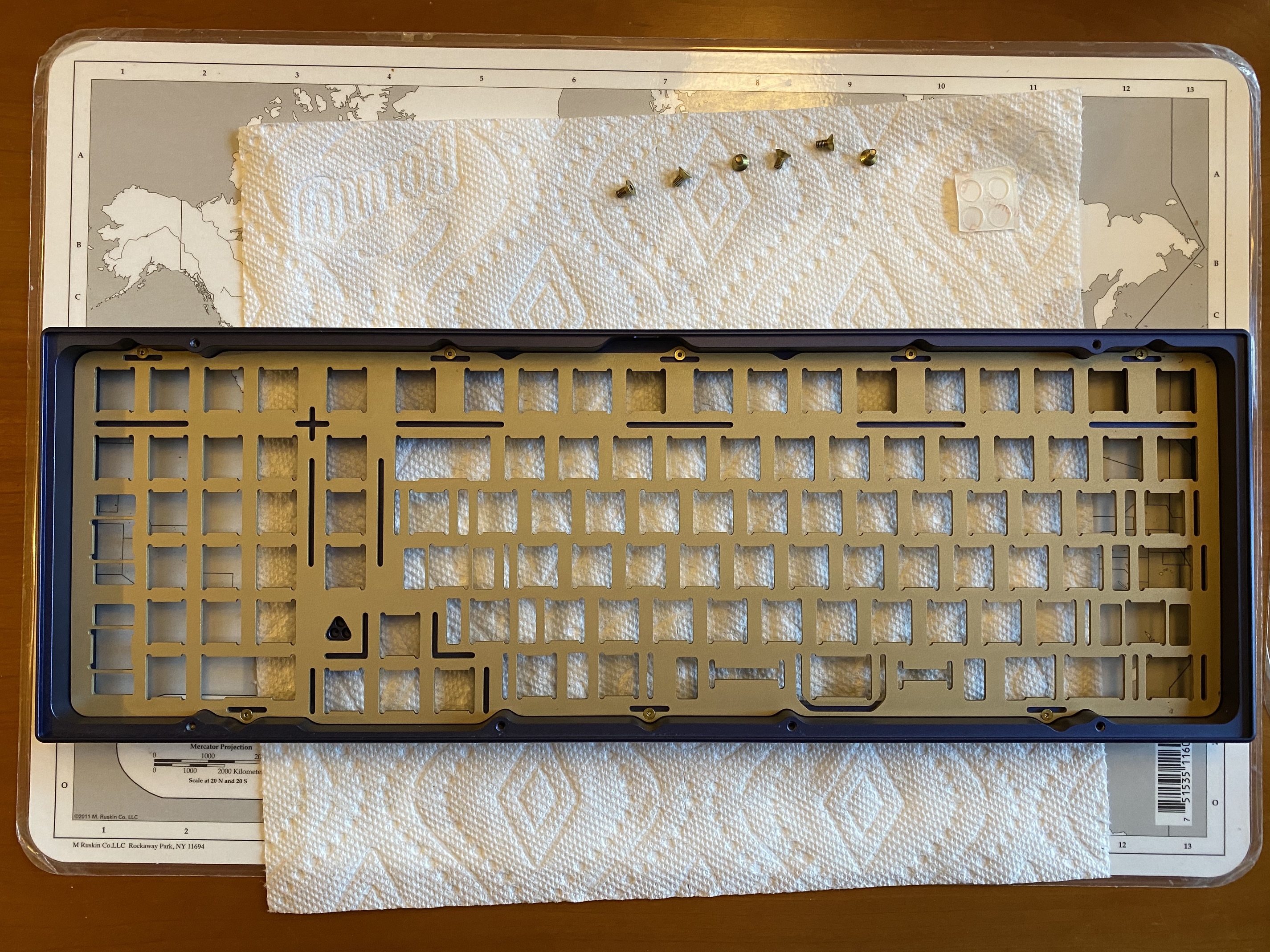
Taking apart the case, we now have a better look at the base. It’s a triangular slab of aluminum, with the weight mounted by screws on the interior base. The brass weight is also engraved with the Drift Mechanics logo.

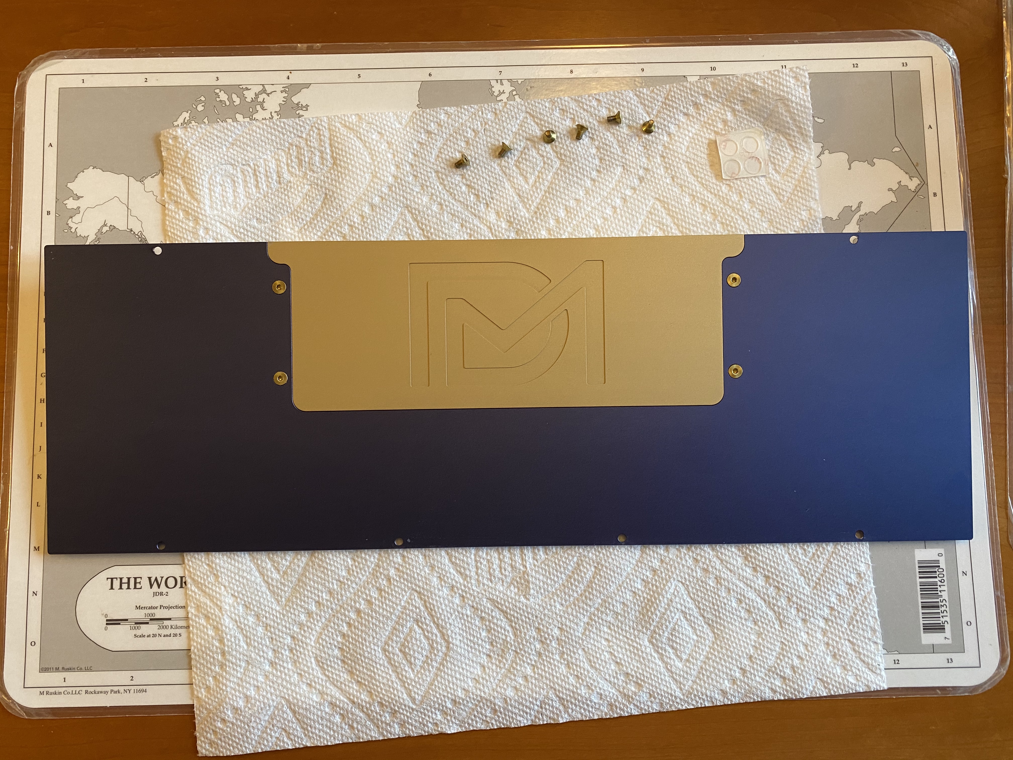
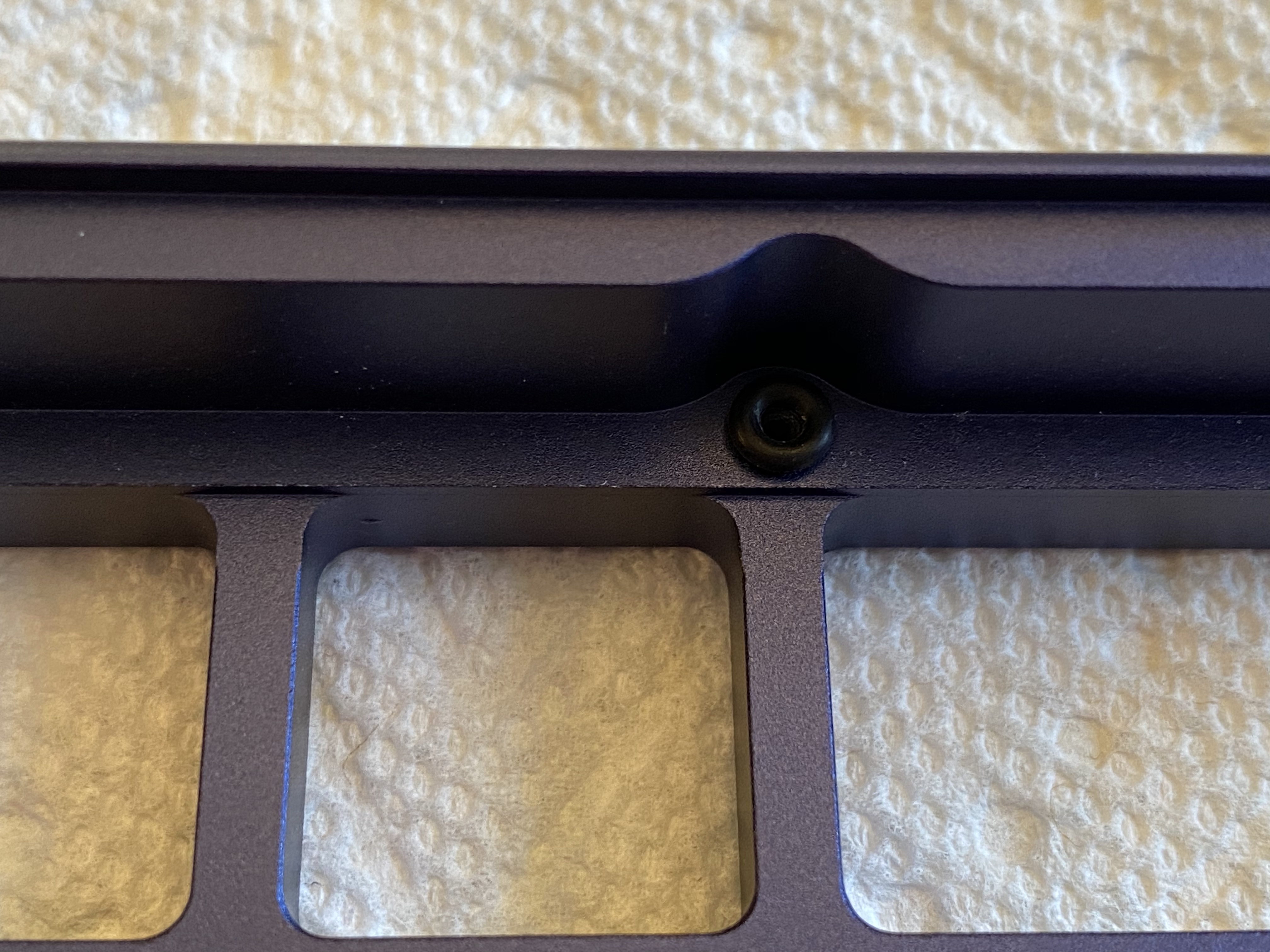
Looking at the underside of the case top, we see that the plate is top-mounted with eight screws - five along the top edge, and three along the bottom. We also see a triangular cutout to make room for the Num Lock, Caps Lock, and Scroll Lock (NCS) indicator LEDs.

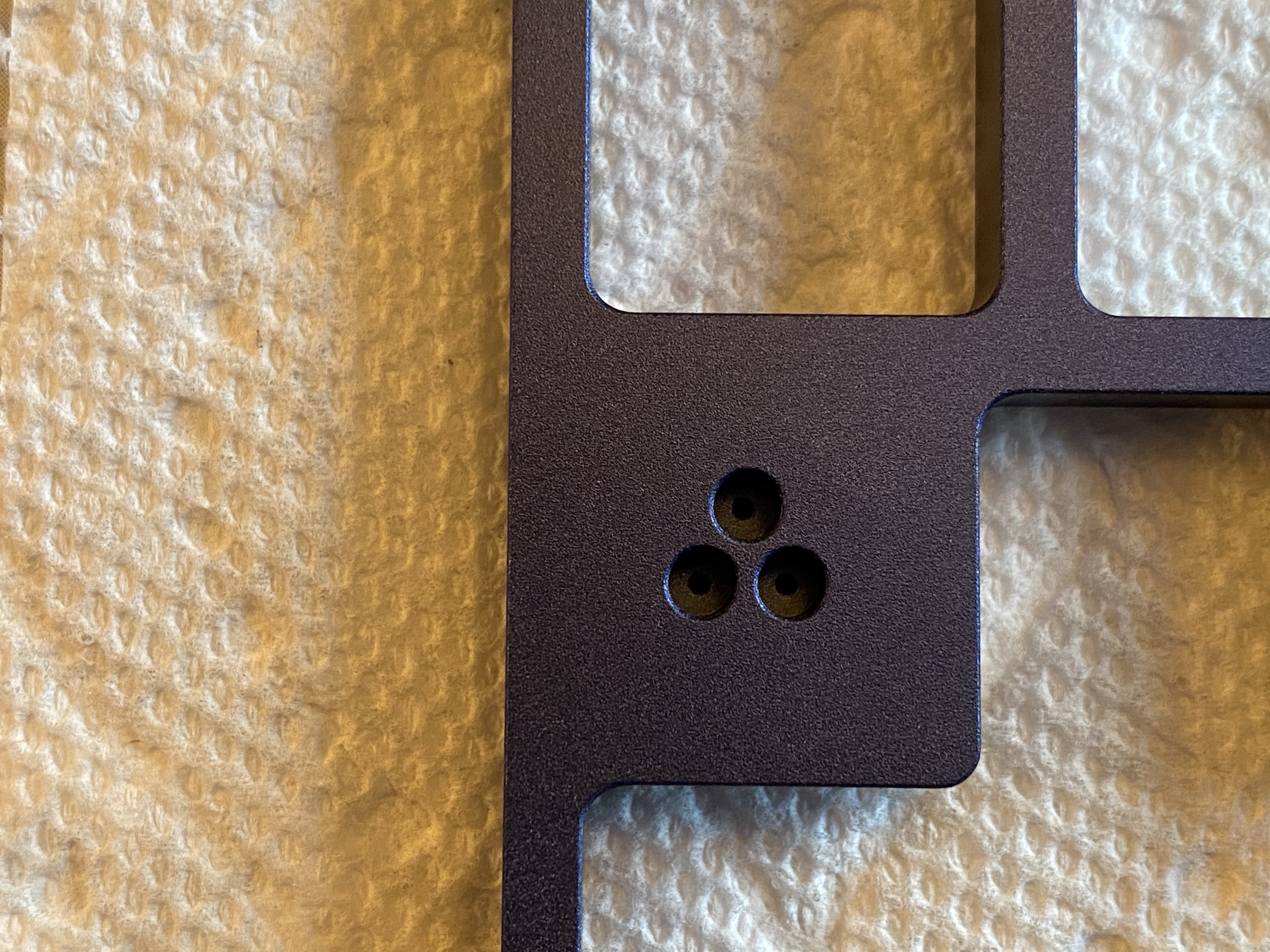
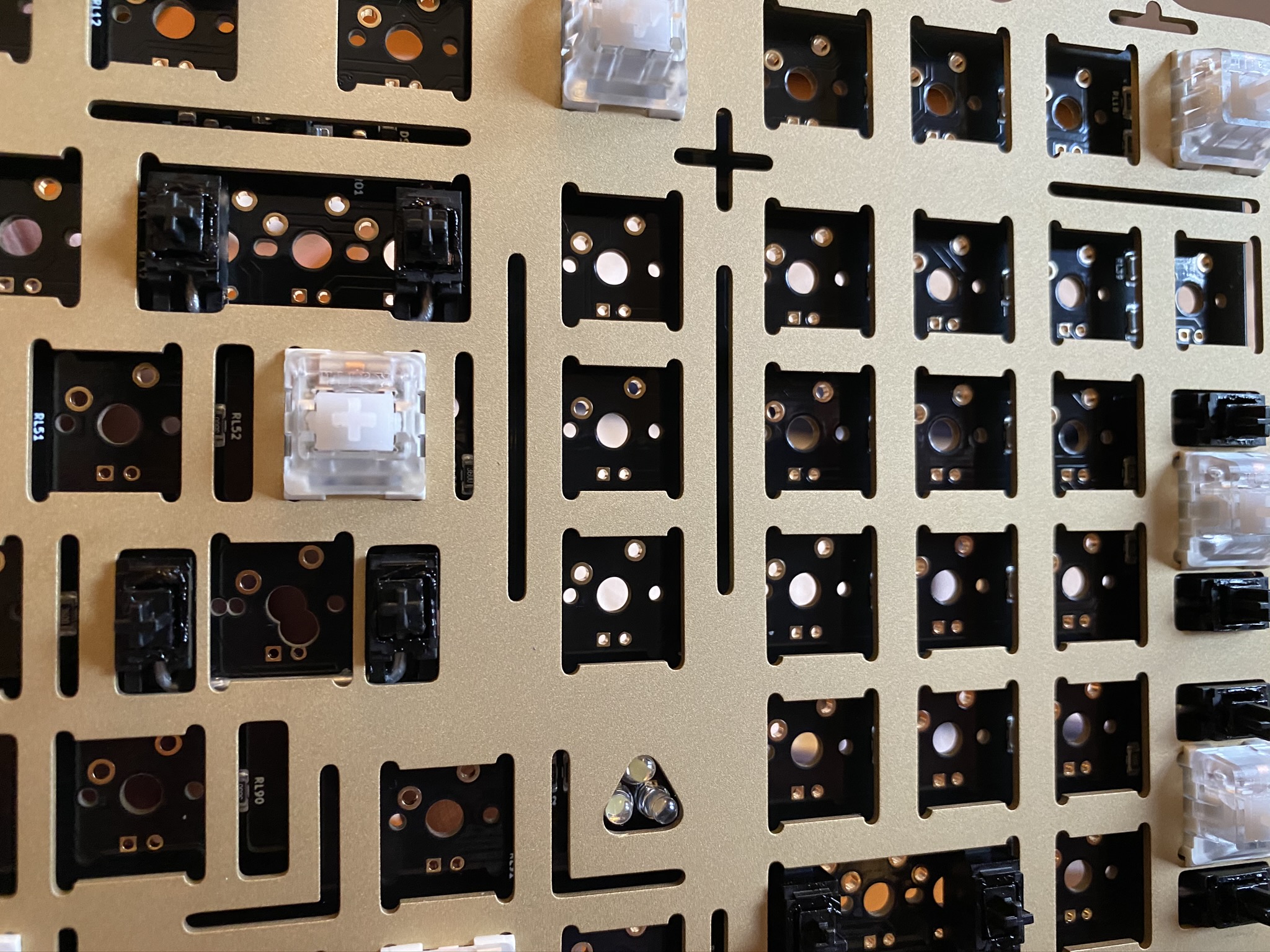
Zooming in closely, we’re going to need to think a bit about installing the NCS LEDs. To prevent light bleed between the LEDs, they’ll sit inside recessed areas, with light shining up through the pinholes.

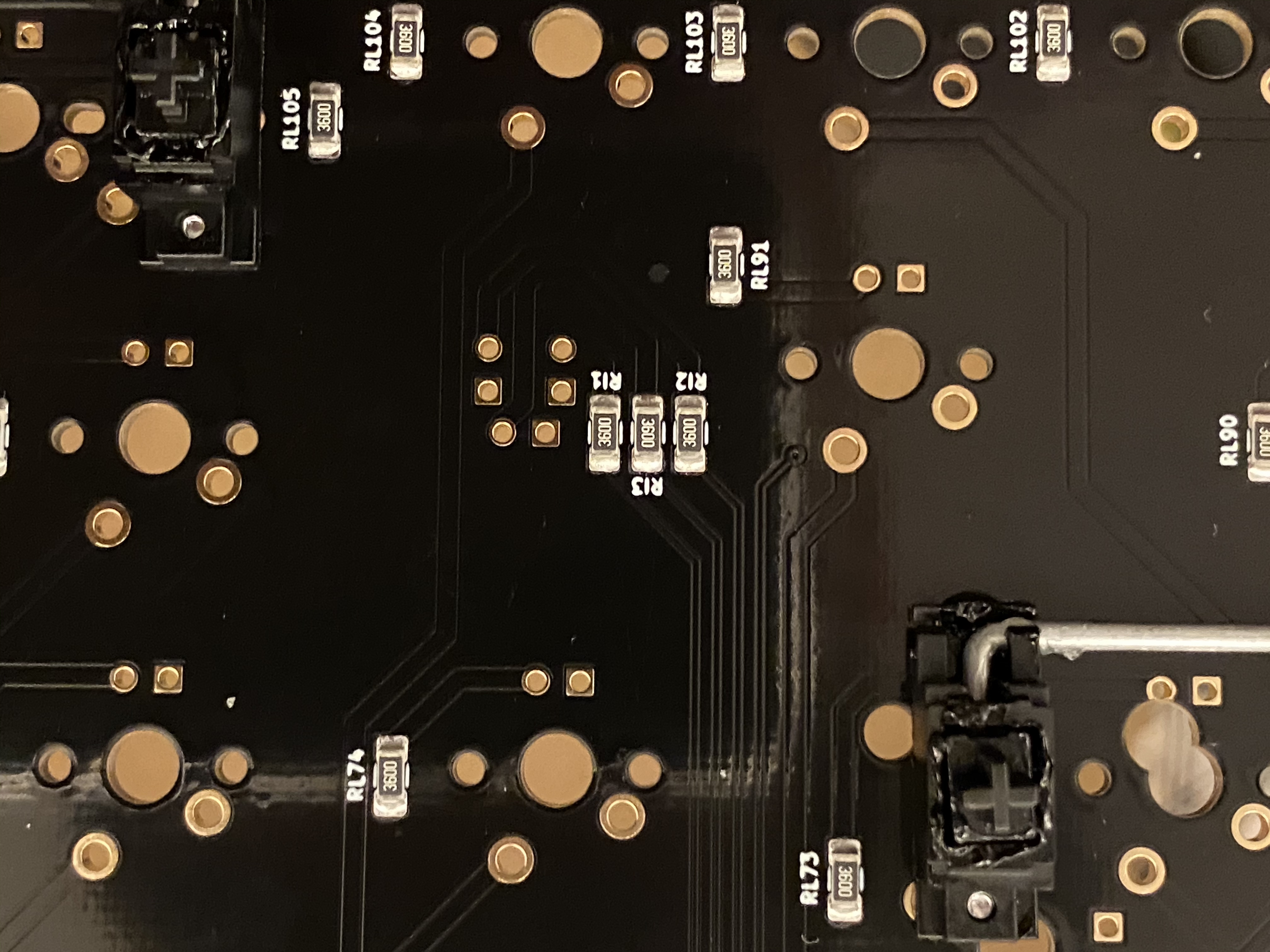
On the PCB, the pads for the NCS LEDs are equidistant from the Enter and numpad 0 stabs (right next to the RI1, RI2, and RI3 SMD components in the center of the photo).

To help ensure good LED placement, I first mounted and soldered a few switches to get the plate and PCB properly positioned into relation to each other. Then, I threaded the LEDs through the hole in the top of the plate, into the PCB pads.

LEDs have to be mounted in the correct orientation to function properly, and up until a few boards ago, I thought there was a convention for this - the long lead of the LED goes through the PCB hole with the square pad. However, I’ve run into a few boards recently for which the LED orientation worked the other way - specifically, long lead of the LED through the circular pad. As a result, I no longer think there is a convention, or if there is, it’s not one that has general agreement, so I test.

If you’ve never tested, this is where it comes in quite handy to have one keyboard with NCS keys already plugged in. Plug in the PCB using another USB cable, hold the LED so that its leads make contact with one pair of pads, and use the keyboard to trigger num lock, caps lock, and scroll lock. If the LED doesn’t light up, switch the leads and try again. Sure enough, here’s another exception to “the rule”: for the Austin, it’s long lead through circular hole.

I found that you have to work the LEDs around a bit before you feel them “fall” into the recessed holes in the case top. Be sure that you have all three seated to the same height before you solder - one of mine wasn’t quite all the way in, but so it goes. Once you’re happy with their placement, it helps to fold the leads over to keep the LEDs in place prior to soldering.

At this point, we can solder the LEDs in place, cut the excess lead lengths, and mount and solder all of the remaining switches.

The Austin ships with O-rings for top-mounting the plate. However, there aren’t recessed cutouts in the case top for the O-rings, which makes installation a bit trickier. We can see this in the following photo.

Do you have tweezers? Get a pair! Here, we can manually position the O-rings and gently place the plate on top, and then use the tweezers to fine-tune the positioning of the O-rings before we put in the top mount screws, saving a lot of trial-and-error to get everything properly seated. With that work done, the top of the case is ready to go.

However, now is the time to remember that the hard reset button won’t be accessible once we put the case together, which means now is also the time to put together a .bin (ARM, remember?) and flash it. The Austin has a stock keymap out of the box, but the Austin PCB is not yet in the main QMK repo, and the code is undergoing some work to make the Austin VIA-ready. However, Gondolindrim’s repo is available in the meantime if you’re one of those people that can hack QMK code and want to get customized straightaway.

I’m one of those people, so I went ahead and grabbed a snapshot of Gondo’s repo and went to work. This was pretty straightforward; the only problem I encountered involved the LAYOUT macros in QMK.

Remember that deep under the hood, a keyboard is physically laid out as a perfectly rectangular logical grid called the scan matrix. Each keypress corresponds to a specific (row, col) coordinate on this matrix, determined by the physical connections to pins on the microcontroller. Since the scan matrix almost never corresponds directly to the actual physical layout of the board (except, perhaps, for ortho boards), you can write a LAYOUT macro which converts between the physical layout and the scan matrix layout - once you’ve done this, you no longer have to think in terms of the scan matrix, and can instead assign key functions to locations in the physical layout.

Why was any of this a problem? Well, the Austin only offers one LAYOUT macro at present, which is a one-to-one mapping from the scan matrix to the physical layout - in other words, the simplification you might normally expect from the LAYOUT macro isn’t present. I noticed this when I first started working on the code, but somewhere along the way I forgot, and on my first flash attempt, the top row of the numpad got garbled. After staring at the code for a while, I finally remembered that the existing LAYOUT macro was just a passthrough for the scan matrix when I noticed that the scan matrix was 19x6 (hence 19 keys per row) - but R1 has 20 columns (with split backspace). Aha! Turns out numpad minus, up on R1 of the physical layout, is down on R5 of the scan matrix. From there, it took all of one minute to fix and flash, and I’m back in business with all of my favorite keybindings.

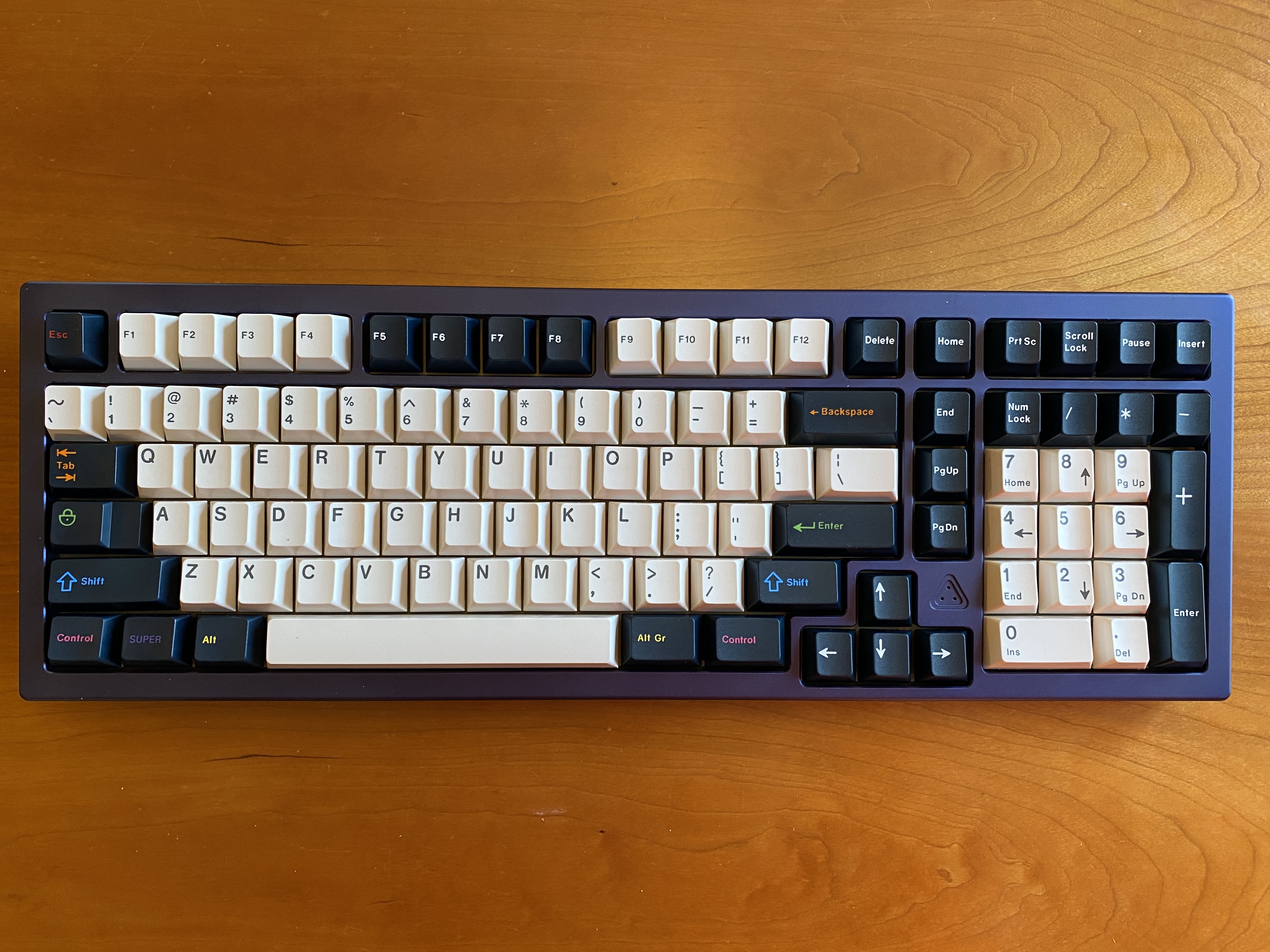
We’re now ready to screw the two case halves together, at which point we’re ready for keycaps!

So, first impressions? The Austin is a solid, premium board. The ano is uniform and smooth, and the sandblasted brass shares the same properties; the overall finishing is very good. The Austin has significant mass, and that translates to an even, consistent sound. The layout is interesting - for those of you that want a few more nav keys than a CP offers without going completely fullsize, this is for you, and you’ll be implementing it on a quality PCB. It has been a good few months for 1800 and CP fans - the HBCP, the EXT65 (which, despite its name and the absence of an F-row, I treat as a member of the same functional layout class as a CP), and now the Austin.

Lessons learned

  • Coming from 78g V2 Zealios, stock Halos (to my ear) offer a crisper, slightly deeper sound. The tactility is almost progressive, in the sense that if you’re a light typist, it’s almost not there, but under more aggressive typing, the tactility pushes back more. Overall, I think a Halo Clear is a decent option for those you that want more moderate tactility, but overall, I thought V1 Zealios did a better job filling that slot in the switch market. YMMV.

  • If you’re a QMK user that likes to code up your board’s features, take a good long moment to review your board’s LAYOUT macros before using them, especially if only one macro is available, and especially if you’re working with a large board - the scan matrix location for a key may be quite far away from its physical location.

  • I would have liked the recessed cutouts for O-rings and a top-mounted PCB reset button here, as on the HBCP; on the other hand, PCB markings to help avoid switch and stabilizer placement mistakes are always welcome, and they’re done well on the Austin. Are any of these things show-stoppers, or even anything that’s going to be a real issue when the build is done? Of course not. But as I work on more and more builds, it’s the little details that catch my attention.

  • A good pair of tweezers: once again, a builder’s best friend.

  • Once again, the value of taking the time to look over all of your components and think through the build, before building, should not be underestimated. The NCS LED installation wasn’t difficult, but it would have been more painful if I hadn’t taken the time to see how the plate, PCB, LEDs, and top case were all going to fit together. Just a little reminder to my future self.

And, with the Austin R2 entering IC, perhaps a little reminder for your future self?

Specifications

case: Austin
- cobalt blue anodized 6063 aluminum
- sandblasted brass weight
case dampening: top-mount O-rings
PCB: Acheron Austin
plate: sandblasted brass
plate/PCB dampening: n/a (relief cuts)
stabilizers: GMK PCB screw-in
- 1x6.25u, 6x2u
stabilizer mods:
- clipped and lubed with SuperLube
- installed with cloth washers
switches: 102x Halo Clears
switch mods:
- springs tub-lubed with Krytox GPL 104
- stems hand-lubed with Tribosys 3204
- no housing lube
keycaps: GMK Solarized Penumbra
HxWxD (without caps or feet): 1.31" x 16.13" x 5.5"
HxWxD (without caps): 1.38" x 16.13" x 5.5"
HxWxD: 1.63" x 16.13" x 5.5"
assembled weight: 3.36 kg (7.41 lb)
15 Likes

Another great build … You are spoiling this community !

1 Like

Great pairing with penumbra and that cobalt. What a lovely shade of aluminum. Nice work.

2 Likes

Awesome build but that’s a lot of switches to desolder when you finally catch the linear bug as I have. :stuck_out_tongue_winking_eye:

2 Likes

Agreed, once you get going on linears it’s hard to go back. I’ve got four boards or so I’m contemplating desoldering, two of them TKLs…

2 Likes

Awesome build!! I didn’t think I ever wanted a board with a numpad on it, but I want something to show off the complete radness that is handarbeit, maybe R2 is what I’m after

1 Like

Ha!

With an FR-301 in the toolkit, the desoldering would only be a minor annoyance. Lubing another 102 switches, on the other hand…:flushed:

1 Like

the feeling when Handarbeit appears on Austin and you realize you’re the proximate cause

Thanks again for this very nice build log!

Do you appreciate the additional column on this particular 1800 layout?
I’m thinking that having PgUp/PgDown/End on it could make layout adaptation easier when switching from a TKL or full size board.

I appreciate it, but probably more for aesthetics than functionality. On 1800-style boards, I’m used to using the 1/3/7/9 numpad keys for those navigation functions, and because the Austin has a numpad, I haven’t managed to retrain myself to use the additional column for those functions - muscle memory carries me over to the numpad.

In some ways I feel like that additional column makes Austin a closer relative to a 65%, as odd as that initially sounds.

2 Likes

It’s crazy how uncommon this is in the real world. I absolutely love those nav keys on a full sized as well as the 1800/1800cp layouts.

Kind of crazy when you think about it how cherry decided to still put the nav keys right on top of the numpad on the G80-1800

But at least the 1800 layout gave us great design cues like the spaced out arrow keys that we still see and use to this day

2 Likes

Build #35: KN2.10^2

The KN2.10^2, designed by Thesiscamper and run by Louis of TYL/ilumkb, was a publically available version of the privately run KN2.10. In addition to the two-tone color schemes, this 60% had some interesting design features which intrigued me, so I purchased the kit during the group buy in late October 2019, for a little over 310 USD, including shipping. I received the complete kit in January 2020, so, at least by group buy standards, we get “Fast” (a little less than three months from start to finish), and, depending on feature set and production quality, that price could qualify as “Cheap” by group buy standards as well. Can we complete the trifecta and achieve “Good”? Let’s dive in.

The packaging is on point, with a nice custom box.

The included PCB is a DZ60-compatible affair, but without the DZ60 swiss cheese, supporting a fixed 7u layout.

The PCB has underglow LEDs, which aren’t going to be of much use in this case - presumably this is a holdover from the DZ60 design. A physical reset button is available next to the caps lock key, and the modifiers are all labeled, which is a nice touch.

I chose an HHKB top, so we’ll need 2x2u and 1x7u stabilizers. I went with C3 stabs primarily to color match. I agree with you, it’s silly! We’ll never see them! But we do what we do.

It’s time to get our first look at the case and start disassembling it to get at the plate. The case is held together by eight screws, only four of which are initially visible, along the bottom edge of the case, so we start by removing those four screws. As an aside, that smudge in the middle of the case is something on the camera lens - in real life, the e-white finish on this board is clean and crisp. We’ll be seeing a lot more of it as we work through the build.

After unscrewing the brass back weight and removing it, we gain access to the other four screws.

Lifting away the base, we now see the plate, and a little bit of the e-yellow top. This is one of the more interesting plates I’ve worked with. Aside from its 4mm thickness, it offers cutouts on the top and bottom edges for a snug fit with tabs in the case top, ensuring tight alignment; this is particularly important for this build since the plate will be visible as an accent around the perimeter of the case.

As the previous photo illustrates, the plate is not uniform thickness; there are CNC-milled cutaways for the stabilizer housings. And, when we flip the plate over to seat it on the PCB, we also see that the perimeter of the plate is thinner. The thick part of the plate seats into the case top.

Let me introduce you to “Holy Goldies” - Halo stems in TTC Gold V2 housings. These frankenswitches have a sharp tactility, but not irritatingly so; I think of them as slightly sharper, higher-pitched versions of Zykos, without all the fussiness with the leaves.

Time to solder in a few switches to hold things together. Also, a quick look at the stabilizer mounting: C3 stabs are screw-in, and although it didn’t really need washers, I put some in anyway.

Soldered and ready for action (and remember - we’re doing an HHKB layout, so don’t put switches in the lower corners!

The plate/PCB assembly seats cleanly on the top again, no problem.

Before we screw this back together, take a look at that engraving on the case bottom’s interior. My photography skills and that e-white finish make it hard to capture, but trust me - there is a lot of fine detail here!

After putting the case together and trying it out, the board is loud - really loud and clacky. It’s been a while since I’ve done a Sorbothane treatment to the case, but I decided to do that here. If you’re a long-time reader of my build logs, you know that I don’t fill the entire case with Sorbothane; I’ve found that a few strips or squares are enough to gain the sound benefits, and I went with a single strip here, centered in the case. Here you can see the switch pin indentations on the Sorbothane, so we know we’re making good contact when the case is screwed together.

It’s worth noting that the case tolerances are quite tight; I had to use 1mm (0.04") thick Sorbothane in this case. Anything thicker would not have allowed the case to fit back together under compression.

With everything reassembled, take a look at that nice engraving on the back side of the case:

We’re done with the functional part of the build…but can we keep this bright orange-yellow theme going? Time to go into arts and crafts mode. Let’s try our hand at acrylic infilling. Full disclosure:
@Jae-3soteric has a nice writeup and videos for the infilling process which I leaned on heavily as a reference for the work that follows. If you’re new to infilling and want to give it a try, I recommend you read and watch all of that material first before following my lead.

First, we need to find a water-based acrylic paint that matches the heavily orange-tinted e-yellow of the case. This looks close enough:

Using a silicone caulk scraper, we can spread a small drop of the paint over the engraving. Applying pressure with the scraper, we are effectively pushing the paint into the engraving. Here I’ve made repeated passes over the engraving to make sure I don’t have air bubbles in the paint, and that everything is filled in completely.

After a first quick pass, it looks like this. Perhaps 2-3 minutes have elapsed since I started infilling.

Next, I use a wet wipe to remove most of the excess around the infilled areas. The first time I tried
this, I used some old dried out wipes that I reconstituted with distilled water, and the wipe I used was too damp, with excess water, and I ended up removing not only the excess paint, but also some paint from the infill. Sigh. The good news is, it comes off easily! After drying the surface and reapplying paint, I tried again, this time with a damp but not soaked wipe, and that worked just fine. Just go out and get some new wet wipes if you try this, and I imagine you won’t have problems.

Note that the removal of excess paint with the wet wipe won’t be perfect, but it doesn’t have to be - the remainder of the paint will be removed later. After the wet wiping, we can still see a yellow smudge around the engravings, but the excess is largely gone:

After that, we let the paint dry (15-30 minutes). Then, we return to the board with a wipe dabbed in a little bit of isopropyl alcohol, and gently run it across the engravings - this will immediately pick up that yellow smudge around the engravings. Try to just sweep gently across the engravings, as the iso alcohol will take paint out of the engravings if you go deeply enough. Once that was done, I let the paint fully dry overnight.

The result on the interior engraving seemed good enough to go ahead with the exterior engraving as well. The only complication here was that I needed some extra hands to hold the surface level to work on it - quad hands to the rescue.

Here we are after the first couple of passes. This required another pass of paint after this photo to get enough paint into the engraving, and after the initial cure, a bit of extra work with iso alcohol to get excess paint out of all those nooks and crannies in the case.

But the end result is quite nice. It really is a straightforward process, and in particular, it’s easy to remove water-soluble acrylic paint with water and/or isopropyl alcohol. I hadn’t seen anyone try this on an e-coating, but it seems to work, and obviously people have been infilling anodized parts - if you try this on some other type of surface, YMMV.

After another day of paint drying, throw some keycaps on the board and we’re done! I built my usual set of macros in QMK using the 60_hhkb layout for the DZ60, and flashed that in the usual way - no issues whatsoever. I note in passing that the DZ60 is now supported in VIA, so I imagine this board is now VIA-compatible as well, adding to the value this kit offers.

We’ve already talked about the speed of the group buy and the reasonable price point - the QC is solid too. The e-white and e-yellow treatments on this board are very clean, as well as the black ano on the
plate. The machining tolerances are also quite good - everything fits cleanly and tightly together, worth noting for a case with interesting curves and cutaways, and a complicated CNC-milled plate geometry.

Lessons learned

  • TTC Gold V2 browns are mediocre switches at best, but the housings are good for frankenswitching; they give a nice sound, particularly with Halo stems, and presumably with other long stems.
  • After proper lubing, Holy Goldies are a reasonably cost-effective and less complicated way to get most of the sound and tactility benefits that Zykos offer, albeit a less refined tactility.
  • It’s worth remembering that Sorbothane is available in a range of thicknesses, and for builds like this one, where tolerances are tight, a thin “film” of Sorbothane may be just right.
  • Given the tight tolerances and the 4mm plate, I’m surprised that the board was as loud it was prior to the Sorbothane treatment - but that could easily just be a function of my switch choice.
  • Acrylic infilling is not difficult, and once you see how easy it is to remove excess paint with wet wipes and smudges with isopropyl alcohol, your fear of ruining your board will disappear immediately.
  • Take a test photo or two and check the results on a big screen before doing the build log - that spot in several of my photos is triggering my OCD. Sigh.
  • This was one of the best group buys I’ve joined, in terms of speed, pricing, and execution. I’ll be keeping an eye for future boards from ilumkb.

Sure, that e-yellow is more than a little e-orange - but who doesn’t like oranges?

Specifications

case: KN2.10^2
- HHKB e-yellow 6063 aluminum top
- e-white 6063 aluminum base
case dampening: 1mm (0.04") 40 Duro Sorbothane strip
PCB: KN2.10^2 (USB-C, QMK, DZ60-compatible)
plate: 4mm CNC-milled black anodized
plate/PCB dampening: n/a
stabilizers: C3 screw-in
- yellow, 1x7u, 2x2u
stabilizer mods:
- lubed with SuperLube
- installed with cloth washers
switches: 60x "Holy Goldies"
- TTC Gold V2 Brown housings and springs
- Halo True stems
switch mods:
- springs tub-lubed with Krytox GPL 104
- stems hand-lubed with Tribosys 3204
- no housing lube
keycaps:
- GMK Carbon R2 Beezarre alphas
- GMK Classic Retro mods
infills: internal and external base engravings
- PEBEO Studio Acrylic (medium cadmium yellow, #23)
HxWxD (without caps or feet): 1.06" x 11.88" x 4.44"
HxWxD (without caps): 1.13" x 11.88" x 4.44"
HxWxD: 1.38" x 11.88" x 4.44"
assembled weight: 1.42 kg (3.13 lb)
11 Likes

First ! Woweee that’s a nice build !!! What is the Nautilus set going to be used on ?

Thanks! I have another e-yellow board in the pipeline that I think might work well, but I think all of the e-yellows out there have the same orange tint as this build, so I’m not 100% sure e-yellow is the move with Nautilus.

As to which board that might be - well, I have to keep some surprises up my sleeve…

2 Likes

What a beauty… and at that price it looks like a steal.
Thank you very much for this great build log!

1 Like