Wow! Thanks for sharing!
1 Like
Uh weee, had some spare time and speed read your builds again ![]()
How’s life ? Are you still in the hobby and preparing new builds ?
1 Like
That’s a lot of speed reading! I hope the material has aged well. It’s always delightful when someone lets me know they’re (still) getting something out of it. Thank you!
I am still in the hobby - while my last build log was for my 43rd build, I just took a look, and it seems I finished my 94th recently. 94 builds. I don’t know why that surprises me, but it does.
I had intended to keep writing and posting build logs, but a combination of things have kept me away:
- Real life: got busy enough with other things that a build-log-every-three-weeks pace simply wasn’t sustainable. If I was really in a writing groove, one log would take half of a day to write. If I wasn’t, a full day was not out of the question. And that assumed that I had the presence of mind to get all the pictures I needed as I was doing the build. On a couple of occasions, I had to go back in and disassemble a board to get a shot I forgot to take, or didn’t realize I needed until writing the log.
- New things to say: I felt that I had reached a point where I was going to be repeating myself, and/or turning the logs into “look at my purchases”. Granted, keebtalk is an ideal forum for that sort of thing, but for me, the entertainment is in the process - figuring something out and making the next board just a little bit better than the last one, and documenting that, hopefully in a useful way. Not to say that I have everything figured out now (I don’t), but diminishing returns have definitely kicked in. Reviewing those 51 intervening boards, perhaps five would have merited a build log treatment.
But, who knows. There are always builds coming down the pike…
6 Likes
Oh wow, I’m glad you are still enjoying the building process and still having fun !
I was also kinda nostalgic and amazed of how much the hobby for the custom boards has evolved in the 2-3 years, with all the gaskets and affordable alu cases and hotswaps and flexy pcb’s and designs and the oversaturated market for everything :))
Feels like a great time to be alive in the hobby and also massively overwhelming if someone is just starting…
What are those 4-5 boards that were worth mentioning in building ?
What are your preferences in sound & switches nowadays ?
I also consider your previous color combo’s really nice so I would be happy to see the new ones too !
3 Likes
I love to look at the build logs to see a method to the madness. I applaud you for that very large extra effort to document everything.
I usually obsess over a newly arrived board for several days or weeks. Trying to decide in my head what switches would work best. Then I’ll dry fit the switches and do some typing to see if I like it. Then it will sit for another week or so untouched as I try to talk myself into either scrapping my original plans or moving forward. This may or may not involve lubing switches, which is never done within the same week of a build.
Once I finally decide to solder, it’s a freaking whirlwind. I won’t stop until the build is done. This is where any interruption will break my spirit or make me second guess myself.
There’s no way I could be taking photos or notes for this part. I think it’s awesome and crazy that you can do that.
7 Likes
The ones that come to mind as learning experiences:
- Not really a build per se, but revisiting the Hasu USB-to-USB and porting it to VIA.
- Hyper7 R3 - lubing 183 switches and 30 2u stabs! My first jumper to get a malfunctioning PCB to work! Proof-of-concept port to VIA!
- CB1800 Zanbato - first 6u spacebar, but more notable for PCB jankery galore (some switch mounts are north-facing for no apparent reason; missing JST connectors; a bad and unfixable PCB; diagnosing a second bad but ultimately fixable PCB).
- Functional60 - beautiful wood and resin, and way too much flex.
- Cloudline - lots of playing with gaskets and comparing to good old top mount.
It took me a while, but @donpark finally wore me down, and I’ve had a foot in Camp Linear for a while now - yes, I’m still dailying the HBCP w/ Zealios that I build logged a long time ago and can’t bring myself to rebuild, but I’m also dailying a Geon Frog TKL with CJs, and really enjoying that board’s sound and feel.
Technique-wise, 9 times out of 10, I’m tub lubing switch springs with 104 or 105, hand lubing stems with 205g0, and for stabs, wire and stem lubing with 205g0, and “plugging the butts” with SuperLube.
I know the grapevine is not a fan of 205g0 for stabs, but so far I haven’t seen (or felt or heard) any issues.
5 Likes
I love hearing about everyone else’s build approach. We all end up with rectangles on our desks, but the path we take to get there can be so different.
It’s amazing to me that you dry fit and try switches before even lubing them. It makes sense. All the same, I can’t imagine dry fitting and then having to remove them all to lube and then putting them back again - that would break me. I have enough trouble getting myself motivated to lube a batch of switches as it is…
The topic of pre-build approach probably deserves its own page.
6 Likes
Sorry. This counterweight may help.
Linear switches are GREAT!

7 Likes
Build #44: Saving a Kepler FC65
What’s the best part of this hobby? No, seriously - what gets you excited about it? Especially if you’ve built lots of boards. Why do it again? And again? And again? We all complain about lubing. We all complain about stabilizers. Stabilizers! Stab mods. Always the stab mods, again with the stab mods. Ticking. Rattling. Sticking. Sometimes I think it’s a fun thing I like to do that isn’t actually any fun at all. It would be easy, especially right now, to just walk away from the hobby. The boom-bust cycle we’ve just gone through, with a trail of vendor collapses and exit scams, and a glut of increasingly minor iterations of last week’s rectangle, would test any hobbyist’s resolve.
So once more, with feeling: why do we still do it?
For me, one possible answer comes from an unlikely source; a board that had very high levels of hype, first as the successor to a beautiful board that was itself a source of drama due to its designer’s scams, then as a limited group buy object of desire with an ever-receding finish line, then, finally, as the last existing board from a vendor who has disappeared, leaving behind an unincorporated business with multiple open and unfulfilled group buys outstanding. An unlikely source, indeed.
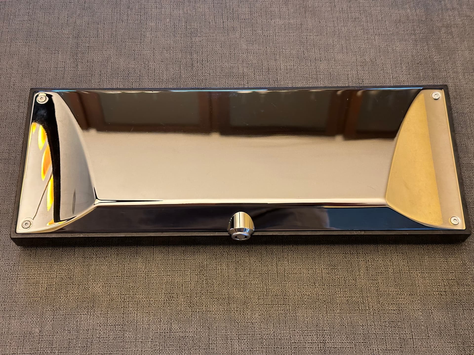
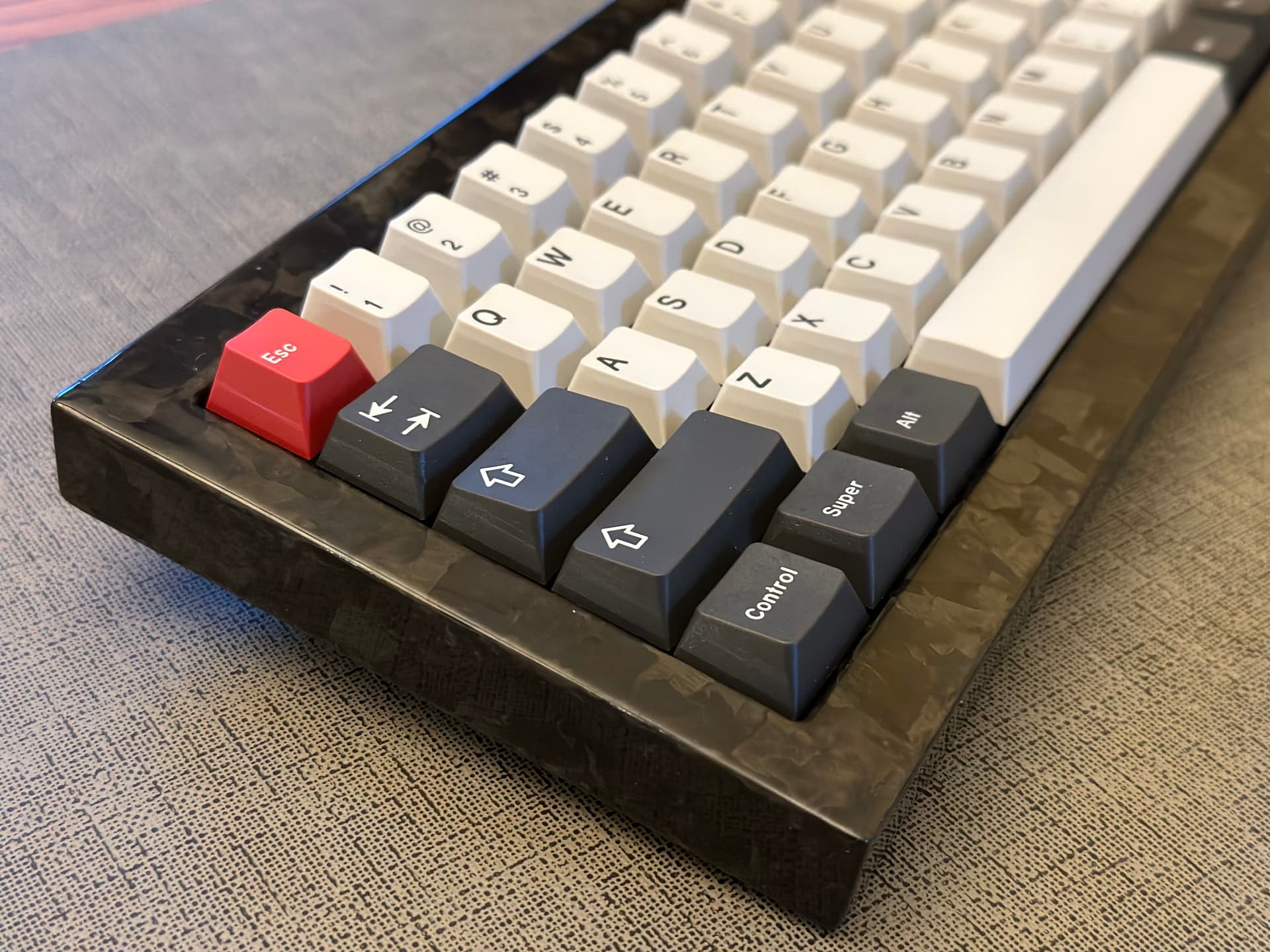
The Kepler FC65, the successor to the Kepler TKL, sported a polished stainless steel base with eye-catching curves, an equally eye-catching polished forged carbon fiber top with just-enough bezel to show off that carbon fiber, and the overkill-and-gimmicky-but-still-lovely LEMO-to-USB board-to-host connection, as well as a novel (for its time) gasket mount. It was and remains a polarizing board, both for the controversy surrounding its creation and production, as well as its unique visual impact.
In what likely will be an unfortunately and increasingly common story, many boards worthy of gracing your desktop as a daily driver, as a standby of your rotation, or even serving as a reference point for a diverse and well-curated collection, no longer have any meaningful level of support from their designers or vendors. At present, the Kepler FC65’s vendor has disappeared, along with the associated Discord server. None of the design materials, most crucially the plate files and PCB design (with LEMO specifics), were ever made publically available. It seems that when any given FC65’s PCB dies, the lack of support and the nonstandard LEMO connection render its return to service vanishingly unlikely for the average hobbyist.
Or does it? One of the positive side effects of the boom-bust cycle, for the end consumer, is the availability of in-stock keyboard components, as well as custom-to-order services with manageable lead times. While we may not always be able to bring a board back to its original out-of-the-box state in the purest sense of the word “restoration”, increasingly it seems possible to restore a board in the functional sense, in the spirit in which it was meant to live on a desk, to be used and enjoyed. That spirit of bringing boards back to life is arguably the genesis of the mechanical keyboard hobby, and the idea of saving a beautiful and unique board from the trash bin gets me excited.
Rules of engagement
So if we’re unable to execute a perfect like-brand-new restoration, what can we do? What are the ground rules? Of course that’s a personal question, and everyone decides those rules for themselves.
For me, it means these rules:
- The external appearance of the board must remain unchanged.
- The feel and sound of the board must remain unchanged.
- Subject to those two rules, anything goes on the internals.
- Where original internals aren’t available, prefer standardized internals - it’s not about just this one board, it’s about keeping as many of them in service as possible for as long as possible.
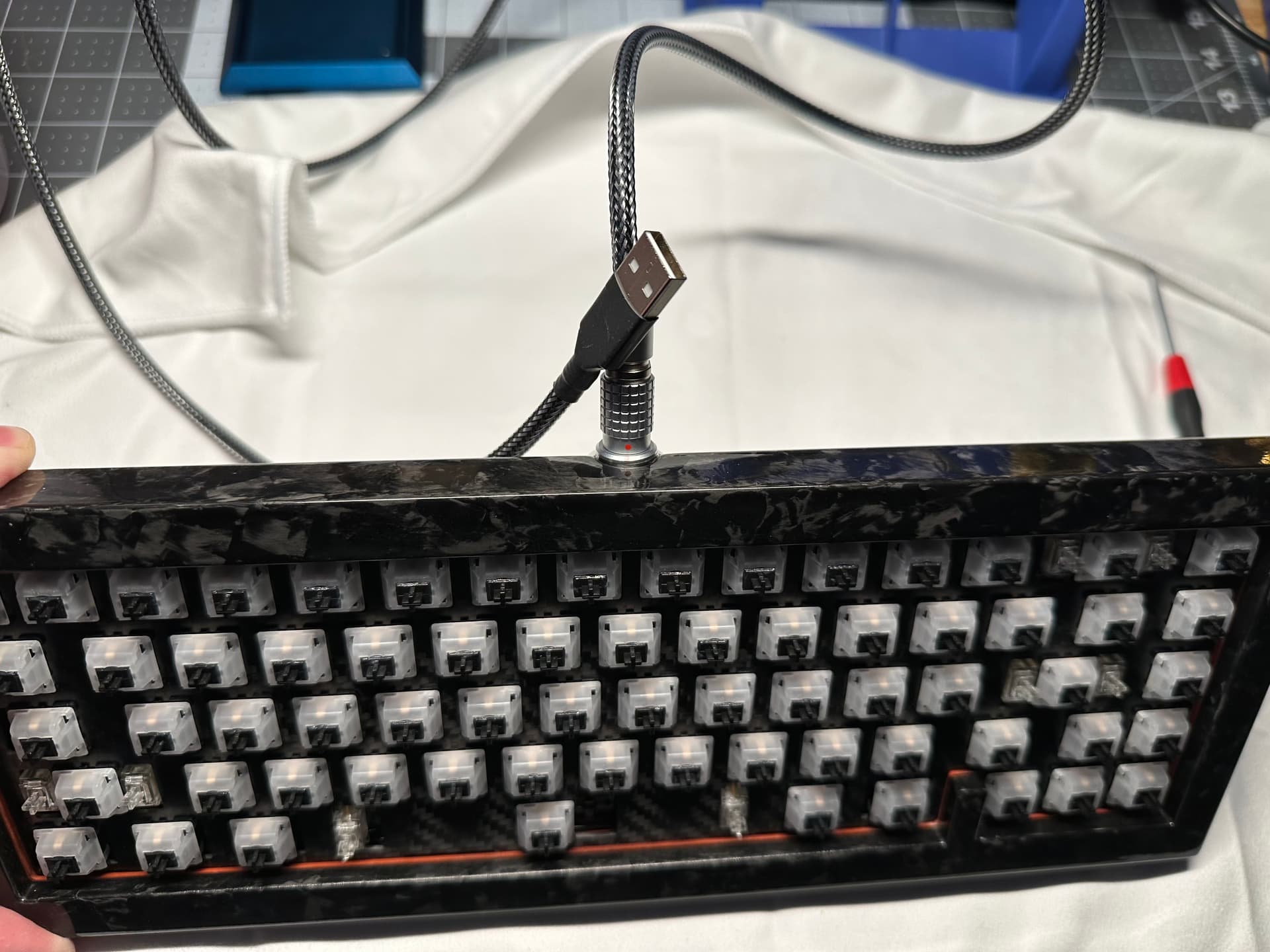
And so it begins. As you’ve likely guessed by now, I obtained a Kepler FC65 on the aftermarket, in non-functional condition, with a non-original PCB and plate. Upon arrival, I confirmed that the keyboard was behaving in very odd fashion, not responding to some keypresses, sending bogus codes from others. The board did have what appeared to be its original LEMO cabling (externally, a USB-to-LEMO cable for connection to a host PC, and internally, a LEMO-to-JST cable for connection to the PCB).
I could have simply removed the LEMO connector from the board and threaded a USB cable through the resulting hole to a new and more standard PCB for a 65%, bypassing all problems with the existing cabling and PCB, but that’s a no-go. The LEMO connector has to stay. If you think the use of LEMO as a physical keyboard connector is nothing more than an expensive design gimmick, you’ll get no argument from me, but my ground rules for restoration are clear: the connector is externally visible and part of the functional design of the board, so getting rid of it, in my opinion, would meaningfully make this a different keyboard. So it’s time for diagnosis; are one (or both) of the cables faulty, is the PCB faulty, or is all of it garbage?
FC65 cabling and pinouts
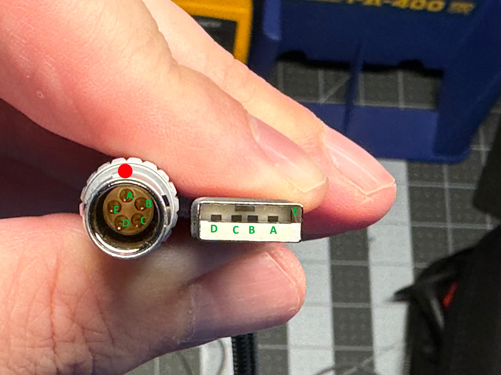
Since I had no information on the pinouts for either cable, some continuity testing seemed like a good place to start. Let’s start by figuring out the USB-to-LEMO cable. Grab your favorite multimeter (Fluke 179 FTW), put it in continuity testing mode, put one lead on a pad of the USB-A connector, and put the other on each pin of the LEMO connector until you hear the beep. Make a note of the USB-A pad and LEMO pin. Repeat until you’ve established the pinouts for the cable. The process is the same for the LEMO-to-JST cable, just a bit more difficult given the tiny JST connector holes. If you’ve ever wondered why good multimeters have such sharp needles of death for voltage probes, this is why.
For those of you who were just here for the pinouts, here you go. Note that the JST connector only has 4 pins, so one of the LEMO pins goes unused.
FC65 USB-A-to-LEMO
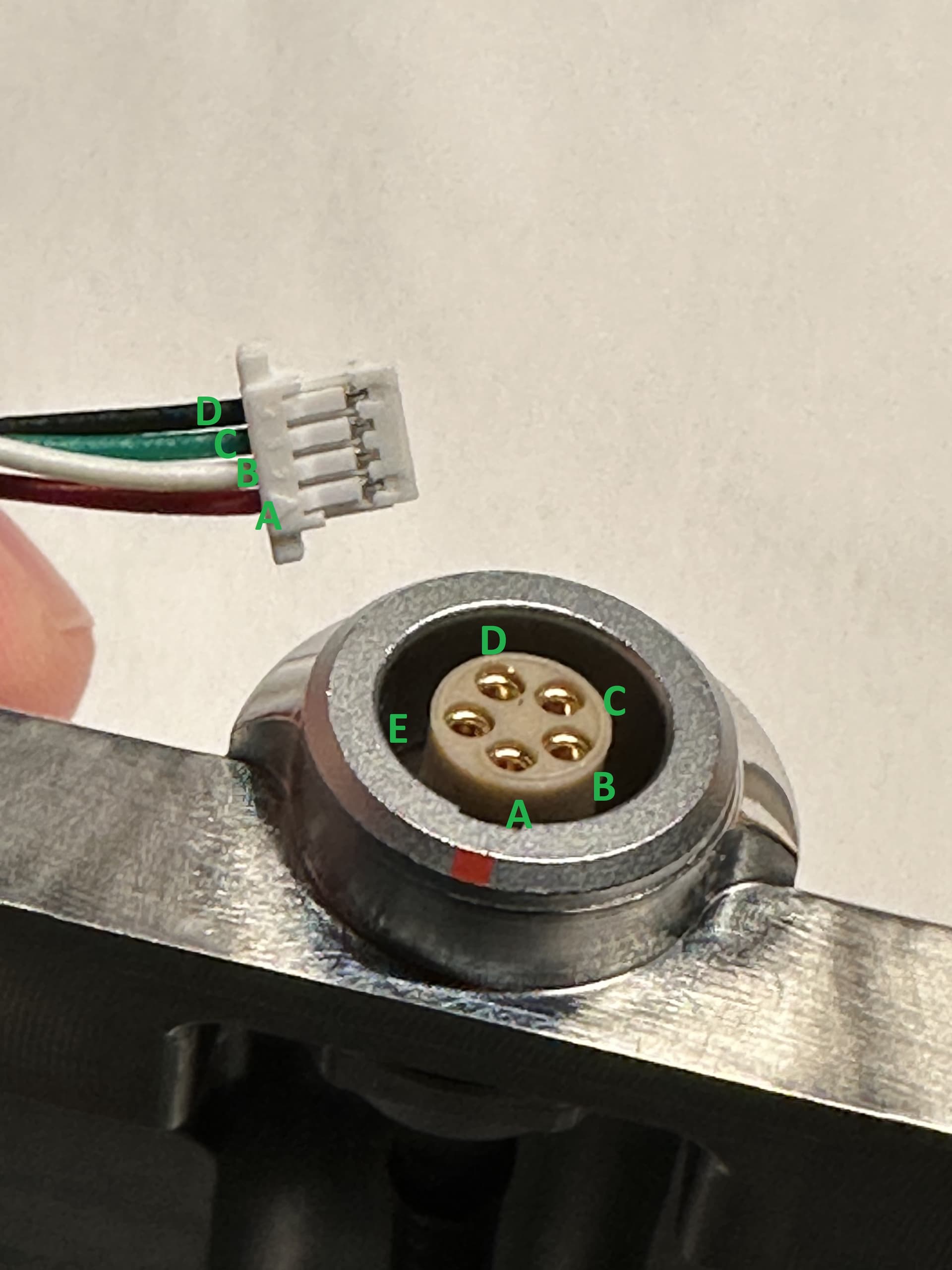
FC65 LEMO-to-JST
And the USB spec tells us which wire is which:
Putting it all together, we have:
USB-A to LEMO:
1 → Vcc → A in picture
2 → D- → B in picture
3 → D+ → C in picture
4 → GND → D in picture
LEMO to JST
A in picture → Vcc → red
B in picture → D- → white
C in picture → D+ → green
D in picture → GND → black
Since I was able to fully determine the pinouts with a continuity tester, it seemed highly likely that the USB-to-LEMO and LEMO-to-JST cables were both operating properly, implying that the PCB was the root problem for the board. The next step, then, was to sanity check the PCB JST pinout, and ensure that the connections were correct, to rule out the possibility that the pins were misconfigured. This seemed unlikely since the PCB was generating some output in response to key presses, but it couldn’t hurt to check, right?
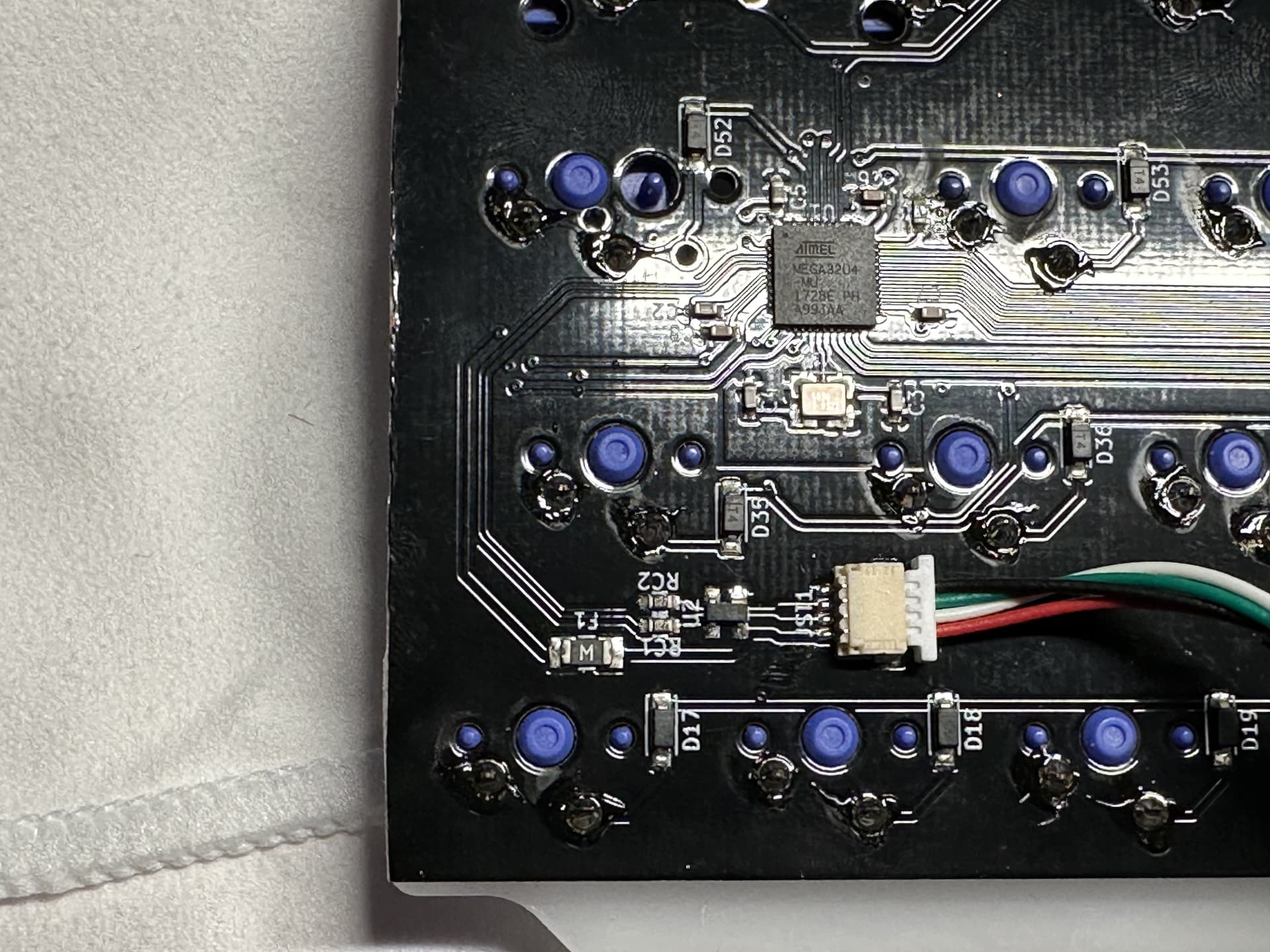
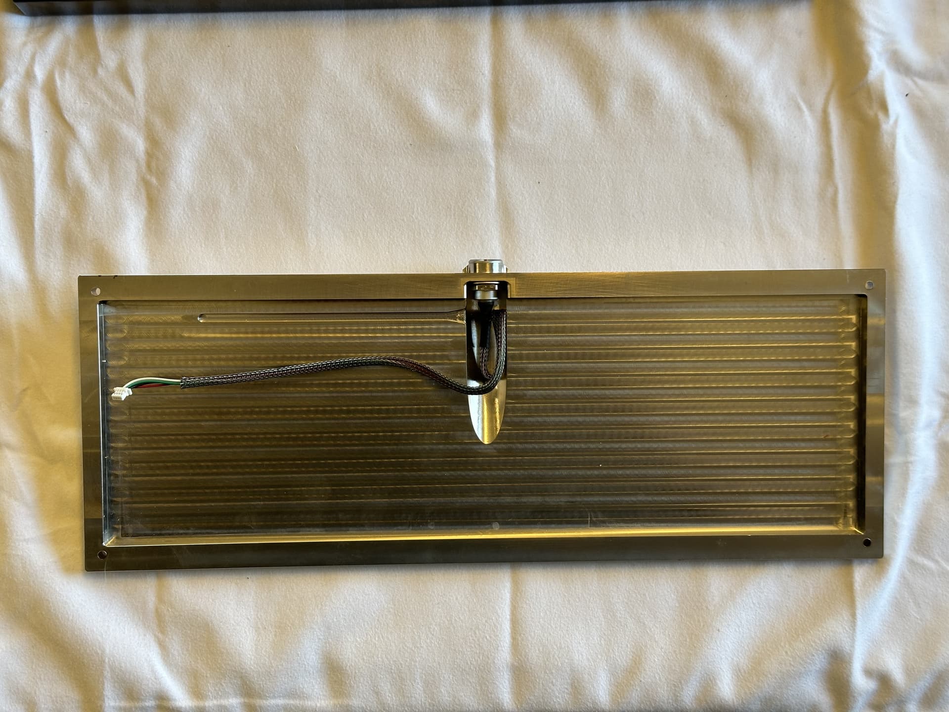
Here’s a close-up of the prototype PCB with the JST cable, as well as the Atmega32U4 MCU; the lighting angle helps see the traces from the JST connector to the MCU. This is helpful because we can use the schematic for the Atmega32U4 to figure out the correct assignment of MCU pins to JST pins.
Here’s an even closer picture of the Atmega. The picture quality leaves much to be desired, but it’s good enough for our purposes. In particular, note the little dot in the upper left corner of the chip:
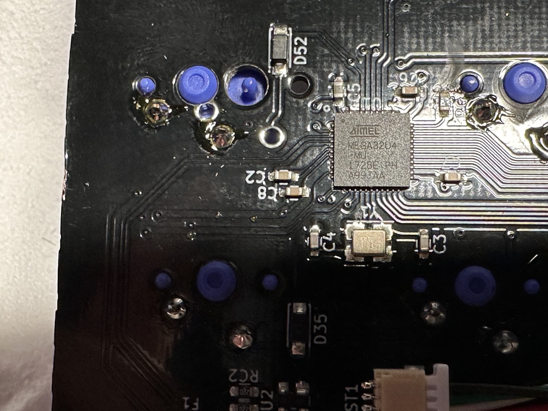
That’s the “index corner”, which allows us to use the following PDF datasheet for the Atmega32U4 to orient our bird’s eye view and determine which pin is which. Skip ahead a couple of pages in the following reference document, and you’ll see a schematic of the MCU:
So, pins 1-11 run from top to the bottom on the left side of the chip, and the pins we care about are:
pin 2 → Vcc
pin 3 → D-
pin 4 → D+
pin 5 → GND
By visual inspection of the earlier photo, we see that the traces from pins 2-5 appear to run where they’re supposed to - the PCB’s JST wiring is consistent with the LEMO-to-JST wiring. From our earlier continuity check, we knew that the cables were working, so it now seemed that the PCB was in fact the problem.
The plot thickens
How did I know the PCB wasn’t working before? When I first received the keyboard, the PCB was mounted in the housing, so I plugged it in and yes, it wasn’t working. To get the photos above, I unplugged the board and removed the PCB/plate assembly from the FC65 housing. With the multimeter handy, I thought I might next do some spot checks with the board plugged in; perhaps there was a short somewhere. Let’s find a key that isn’t working and start there, right? I plugged the PCB/plate assembly back into the PCB, fired up VIA, and…
…it’s working. Every key. Normal behavior. WTF. And staring at the PCB/plate housing, and then
at the housing base, a large chunk of conductive metal, that’s when it hit me.
Where is the bottom gasket??
The Kepler FC65 (and its predecessor, the Kepler TKL), use an “interesting” approach to gasket mount. The gaskets themselves were cut from silicone sheets to match the rim of the bottom housing, and the inner rim of the top housing. Two of the gaskets are layered inside the top housing, with cutouts for the screws that hold the top and bottom housing together. (Why two instead of one? I don’t know, but I suspect an artifact of the design or the production process for the CF top. A second layer might have been needed for the top housing to line up cleanly with the bottom once the screws are in.)
A third gasket lies on the rim of the bottom housing, and together, the top and bottom gaskets sandwich the rim of the plate. Without that third gasket, the plate was resting directly on the rim of the bottom housing. The plate was POM, so in itself that wasn’t a problem. But the missing additional clearance the gasket provided could easily be a problem. Were we just shorting out random switch pins on the PCB every time we pressed a key? A solid hypothesis, and one that would be easy enough to test - if only I had that third gasket, or a still-functioning vendor able to provide one. So now we have a new problem…
Make your own gasket
Fortunately, we have at least a little bit of information available on the web. From the original specs for the board, the gaskets were made of 40A silicone. If we’re willing to assume that the third gasket was the same thickness as the first two, some fiddling with calipers suggest a 1/16" thickness. (“Fiddling” is the correct technical term for trying to measure the thickness of a rubbery surface with calipers.) So, if we can find a sheet of 1/16" silicone long and wide enough to accommodate the footprint of an FC65, we just might be in business.
Amazon to the rescue:
https://www.amazon.com/Rubber-Silicone-Thick-x12-40A/dp/B076C7KMCB/
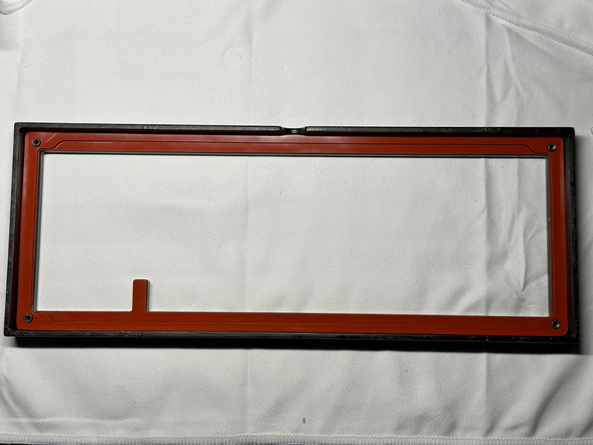
Can you laser cut a silicone sheet (safely)? I didn’t know, and it’s a moot point anyway as I don’t have a laser cutter handy. It’s arts-and-crafts time. Flip over the FC65 base on to the silicone sheet and press it down to leave an impression on the sheet (you won’t need a lot of pressure, that base is a chonker). Lift the base, trace the impressions of the base rim, get a good pair of scissors, and get to work. Place the result on the rim of the base, see where the rough cuts overhang the edge of the board, trim them, and repeat until happy. I didn’t have an awl handy to punch screw holes through the silicone at the corners, so I opted to simply remove the corners entirely to stay out of the way of the screws.
It’s by no means a perfect clean cut, but I wouldn’t expect that to affect the feel of the board in any way, and just as importantly, it gives us additional clearance between the base and the switch pins on the PCB. It’s time to test our hypothesis - with our handmade third gasket in place, will the board now function properly?
Yes! All keys work, no issues, even under intentionally heavy typing to try to short out the board.
So that’s well and good, and I could have stopped here and used the board myself. But we’re not done. As noted earlier, the PCB I had was a prototype for a different board that never ran. While I could have stopped here and used the board myself, my ground rules dictate standardized internals. We want to keep this FC65 (and others!) working well into the future.
Functional PCB and plate replacements
As I mentioned earlier, one of the positive developments in the past few years is the increased availability of in-stock components, among them standardized PCBs for various popular form factors. Even better for this specific project, there were multiple options for 65% PCBs with JST support. I chose to experiment with a WT65-G, which supported the same layouts as those supported by the FC65’s original PCB, and offered a JST connector onboard. While I still didn’t know at this stage whether the pinouts of the WT65-G matched those of the FC65 JST, in the worst case I thought I could standardize by simply put a new JST connector on the LEMO-to-JST cable with the correct pinouts. “Simply”. As if I’ve ever built a JST cable before. I make myself laugh sometimes.
But sometimes we just get lucky. The WT65-G also uses an Atmega32U4, and a inspection of its traces indicated that its JST connector used the same pinout, and it looked like the same physical JST receptacle as that on the prototype PCB. In other words, the LEMO-to-JST cable should just plug right into the WT65-G and work out of the box. Do you feel lucky?
I did, and yes, we are good with the WT65-G as a replacement, at least from an electrical standpoint. A quick manual fitment suggested that the WT65-G would also fit in the housing, so now we’re down to one remaining problem: the plate. Is there a free-for-non-business-use 65% plate file we could use with the FC65 gasket mounting style? We’d have to get really lucky for the screw holes in a random plate file to be positioned exactly where we need them, so we need a plate with enough bezel to sandwich between the gaskets, but no coverage at the corners, to avoid interfering with the housing screws.
After some sleuthing, I found the Keycult 1/65 Rev 1 plate. Enough plate bezel to work with the gasket sandwich without exceeding the case dimensions, layout compatible with the WT65-G and the FC65, and a plate file available for public use. These days, multiple vendors offer custom plate-cutting services, so I had some plates cut to test whether the KC plate together with the WT65-G might offer an off-the-shelf solution for FC65 internal replacements. A few weeks later, with new plates in hand, it’s time to find out if we can reach the finish line.
Back to life
Lubing and modding, living the life. I’d like to tell you that in the intervening time since I last posted here, my lubing technique has become dramatically more efficient, and I can blast through a pile of switches and mod stabs in a couple of hours. Yes, I would very much like to tell you that.
Back here in reality, it’s still as slow as it ever was. I would like to think, however, that these days the results are consistent from switch to switch and stab to stab. More often than not, it’s 205g0 on the switch stems, with particular focus on the small “rail” that runs around the top of the stem, and a tub-lube of 104 or 105 for the springs. And generally speaking, that’s it, nothing on the housings. I’ve been finding that the stem rail is where sound and feel live, at least for me. For stabs, it’s whatever strikes my fancy for the wire ends and housings; the important part is “plugging the butt”, a squirt of SuperLube in the underside of each stab housing after the stab is assembled.
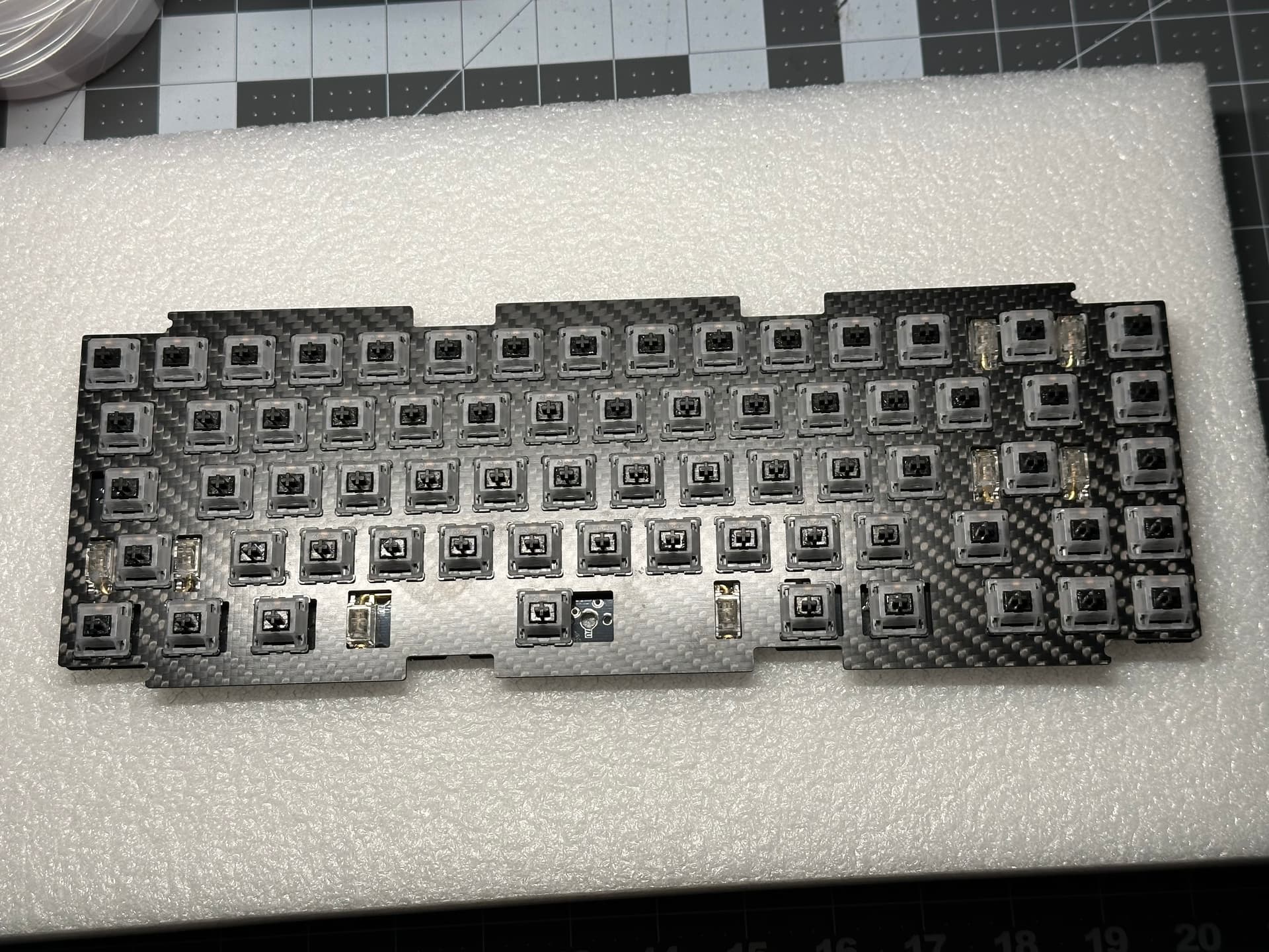
Normally, I’d be done with the mods at this point. But after doing a quick PCB test in VIA (all good), I noticed that about a dozen of the switches had an unpleasant “plasticky ping”. My usual lube treatment around the stem rail is pretty light, and it just wasn’t enough for several switches. In ancient times, this used to mean a desoldering session to remove the switches, take them apart, add lube, and resolder. In our current world, it’s easy to obtain preloaded syringes of 205g0, which make it straightforward to depress a stem with tweezers and use the syringe to apply a tiny dab of additional lube along the stem rail.
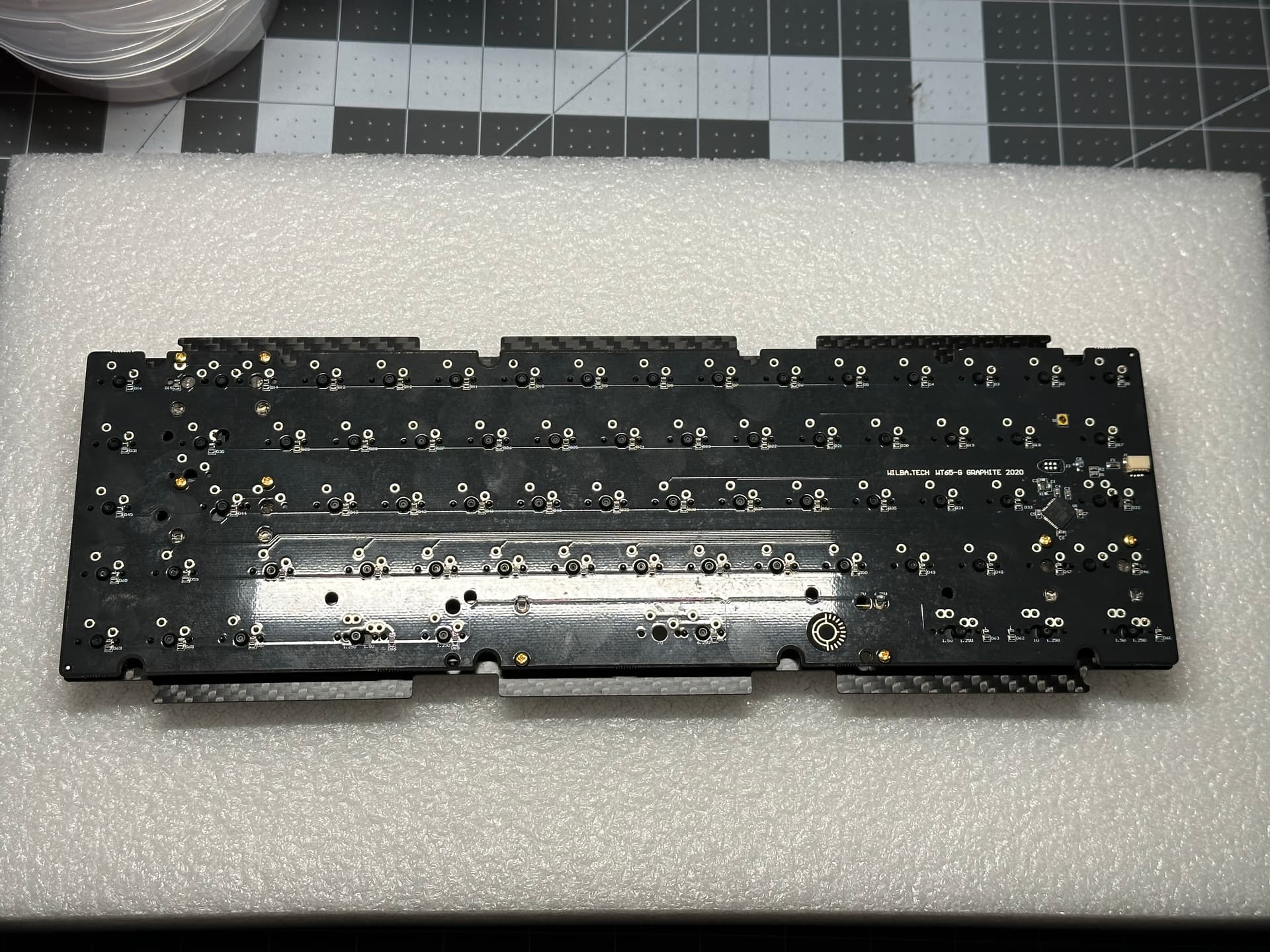
My WT65-G came with a daughterboard and JST cable…
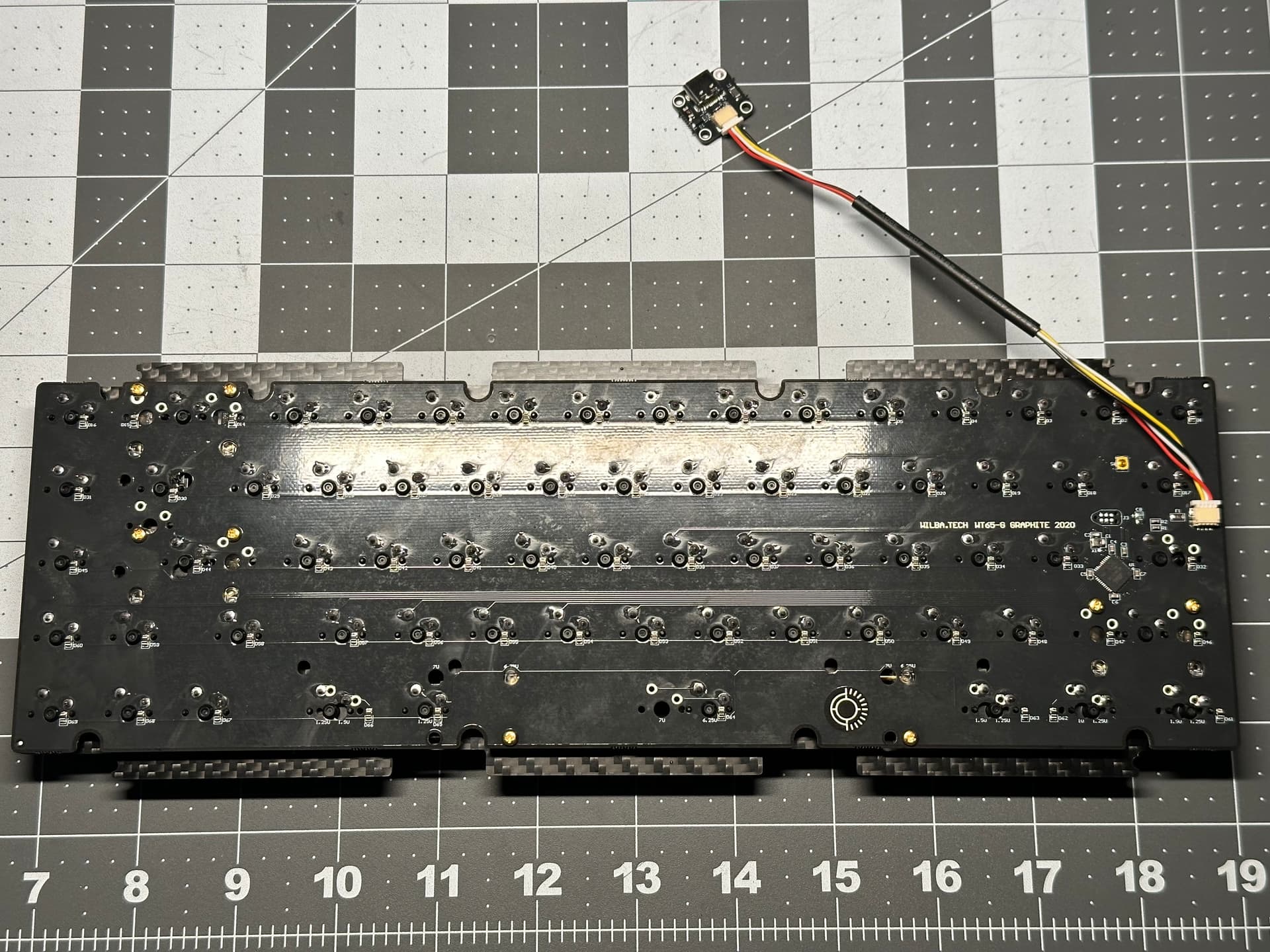
…but as we saw before, we won’t use it since we have the LEMO-to-JST assembly, so just gently remove the stock cable and daughterboard. (Keep it - with standardized daughterboards and JST pinouts, this will likely work with many other PCBs, if you ever need a spare.)
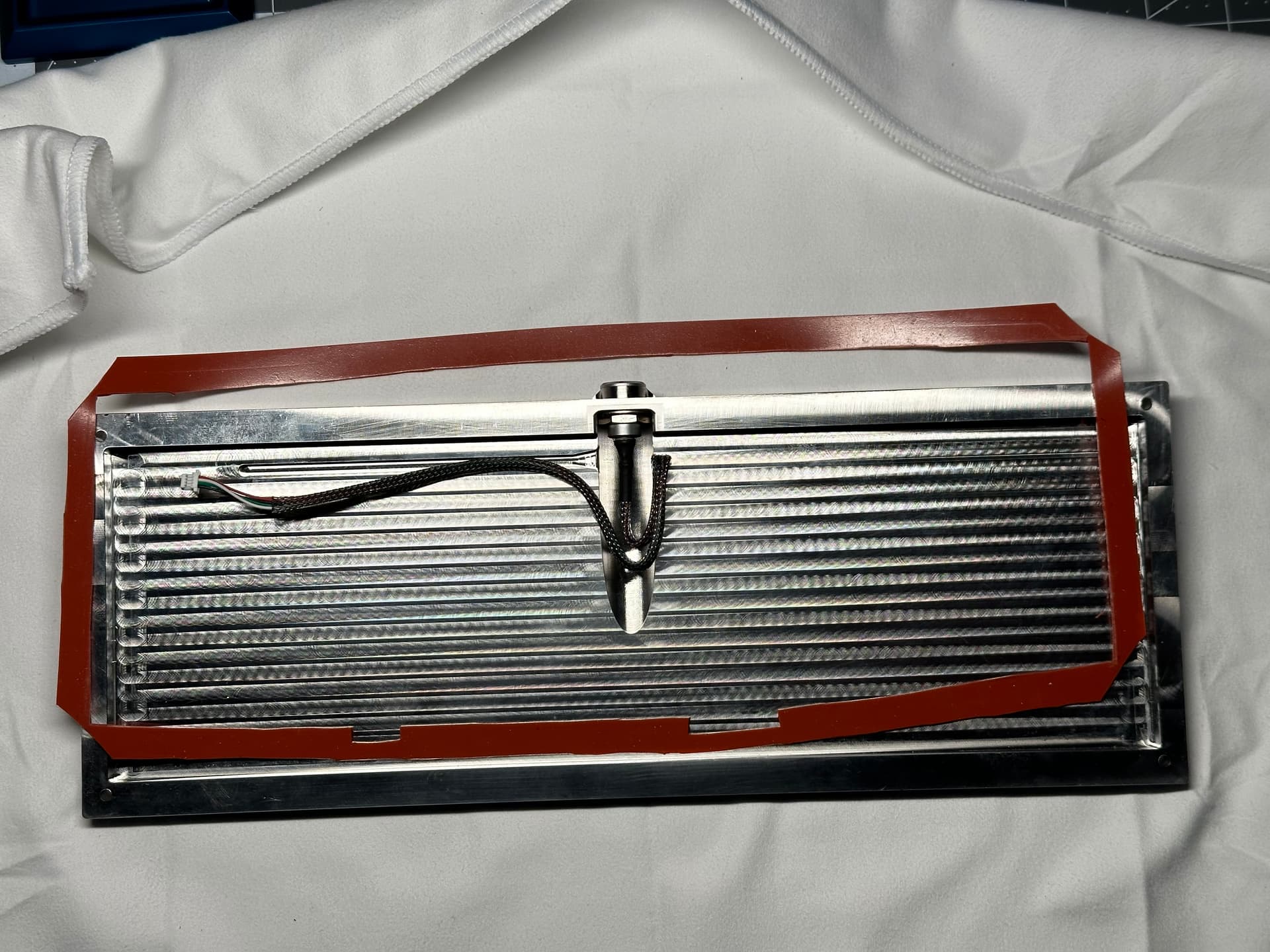
It’s time to put everything together. Place the hand-cut gasket on the bottom housing. Connect the LEMO-to-JST cable to the PCB, and place the PCB/plate assembly on top of the gasket. This can be a little finicky, as the gasket wants to slide and flop around. If I was to do it over again, I might first use a glue stick and smear a bit on the gasket to hold it steady before dropping the PCB/plate into place. Note also that there’s not a lot of room in the housing for the LEMO-to-JST cable, so it can take a few tries to get it wedged into place for the PCB/plate to sit flat.
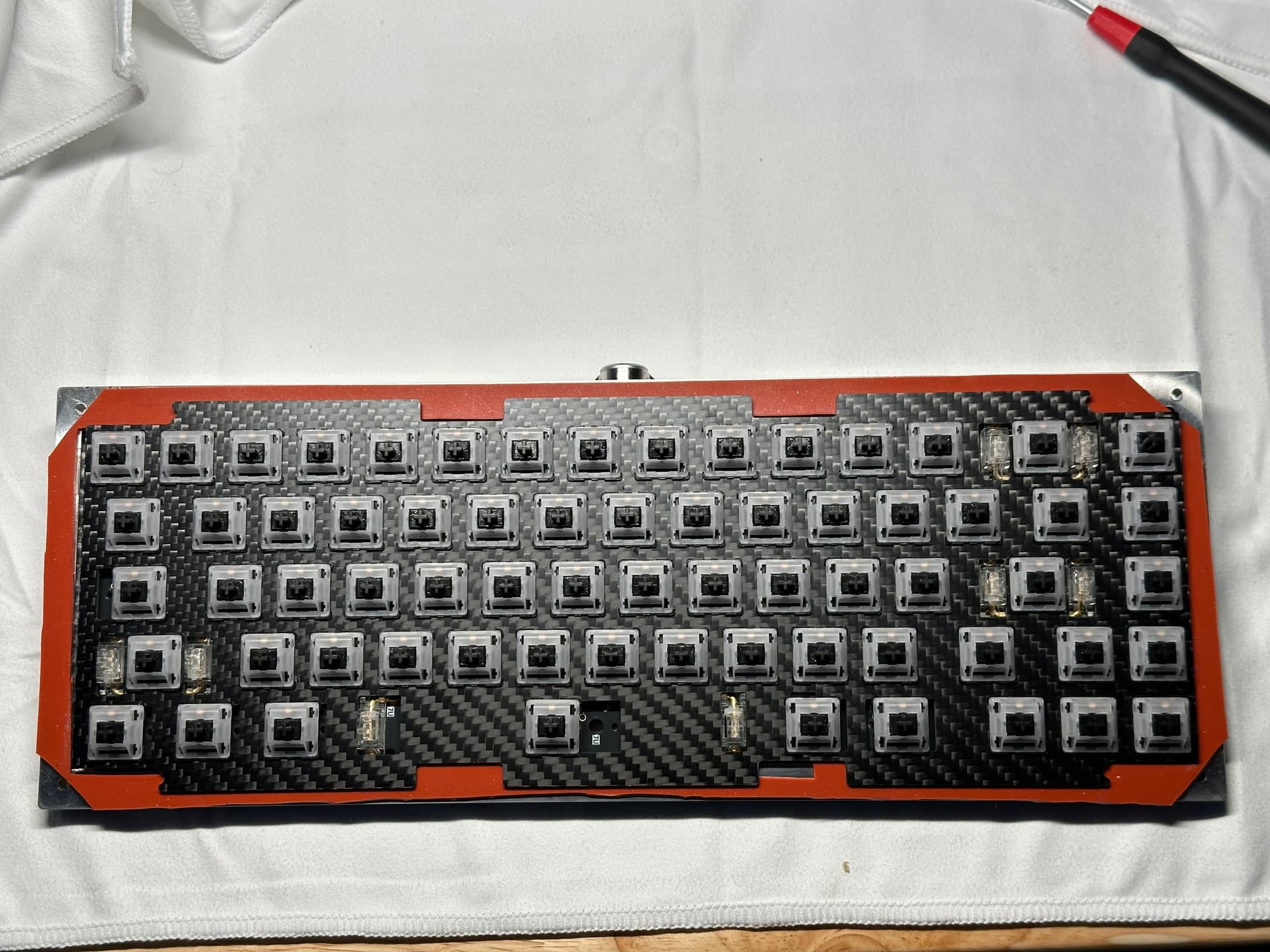
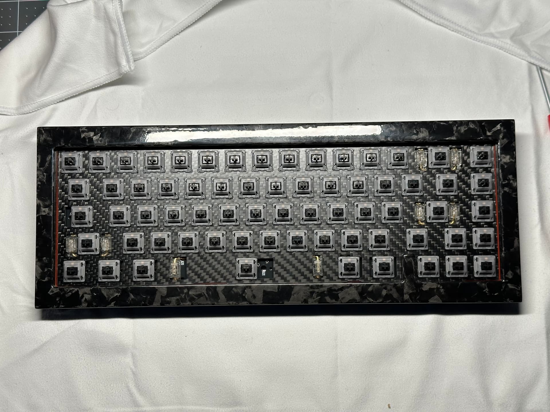
At this point, we can put the top housing in place and test fitment before putting the screws in. You’ll note that neither the plate nor my silicone scissor job is perfect. Because the KC plate has almost no additional bezel on the sides, there is a slight gap where it’s possible to see the gasket. Again, it took a bit of finicky fiddling to center the PCB/plate, as the LEMO-to-JST cable is quite stiff, and kept pushing the PCB to one side. Once you get it aligned, it’s a bit of a juggling act to maintain compression on the housing while flipping the (heavy) board over to get the screws in.
Again, a quick test of the PCB now that it’s in the board, to be certain we’re not shorting out. No shorts, and life is good. A quick peek at the LEMO-to-USB connector in use:
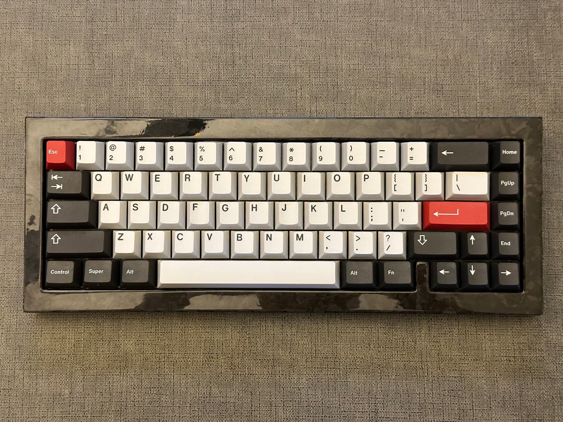
We’ve come full circle. This FC65 is back in service, looks and feels great, and now has standardized and easily replaceable internals. I hope you’ll agree that (at least for this board) the process didn’t require much in the way of specialized knowledge or impossible-to-source parts. So why am I still in it, you ask? Saving a board, especially one like this, from collecting dust on a shelf, or even worse, going into the trash bin?
Today, right now, with this board: best part of the hobby.
Lessons learned
- If your PCB is acting strangely, with intermittent output, check for shorts, especially if the case tolerances are tight. In this case, a missing gasket was the culprit, but it’s still worth a check early in the diagnostic process.
- You may not have much or any experience with circuit diagnosis - but you can do continuity testing and read basic electronic spec sheets without much experience, and since that testing is done on a circuit that isn’t powered up, you’re unlikely to break anything doing the tests (or at the very least, make things worse than they already are…)
- You don’t need a good multimeter or a nice set of calipers on day one in the hobby, or even day one hundred. But on whatever day in the hobby this is for me, the ability to take accurate dimensional and electrical measurements has paid for itself many times over.
- It’s almost too obvious to state, but let’s state it anyway: if the board uses standardized layouts and circuit pinouts, and you’re not hung up on exact replicas of the internals, it can very likely be repaired.
Specifications
case: Kepler FC65
 - forged carbon top housing
 - polished stainless steel bottom housing
 - LEMO-to-USB-A connector and cable
 - custom 40A silicone-gasket mount
 - bottom gasket hand-cut from 40A sheet
case dampening: n/a
PCB: WT65-G (third party replacement)
 - QMK/VIA support
 - Kepler FC65 LEMO-to-JST internal cable used in place of WT65-G DB/JST
plate: Keycult 1/65 Rev 1 (third party replacement)
 - carbon fiber, custom cut
plate/PCB dampening: n/a
stabilizers: Zeal V2 transparent
 - 1x6.25u, 3x2u
stabilizer mods:
 - sliders and wires lubed with Krytox 205g0
 - SuperLube in underside of assembled stab housing
switches: 67x opblack
switch mods:
 - springs tub-lubed with Krytox GPL 104
 - stems hand-lubed with Krytox GPL 205g0
keycaps: GMK Mercury
HxWxD (without caps): 1.31" x 5.0" x 13.0"
HxWxD: 1.5" x 5.0" x 13.0"
assembled weight: 3.09 kg (6.81 lb)
15 Likes
Awesome work man, thanks for posting this! I wholeheartedly agree the restoration of old, unique boards is the genesis of this hobby & it’s kinda great to see that aspect starting to come into play with the customs we bought some years ago. Just something that perfectly aligns with the spirit of the hobby IMHO!
3 Likes
Great to see you posting builds again !
The Kepler boards are just fantastic piece of art, it is super cool that you managed to make one live again ![]()
As for the Lemo connector, I think it is not just a gimmick as I found the USB housings used in many USB daughterboards (including mines) of very bad quality, seeing that the USB cable can wiggle significantly inside those are concerning to me.
As a spoiler, my next design will probably use a Lemo connector to get rid of this mechanical issue (and also because it is super cool ![]() ).
).
How much does this baby weight ?
It does look so damn cool to see one working on a desk ![]()
2 Likes
Great to hear from you!
LEMO is controversial, for sure. When you say that you see wiggle, do you mean that the daughterboard moves, the connector on the DB moves, or that the tolerances of the connector are too forgiving? I’m guessing it’s the latter, but I haven’t really seen that either…hence my opinion. But I’ll agree that it does look cool. I was at the NYC Keycon in 2019, and someone there had a Kepler TKL with the LEMO attached and was dangling the board by the cable to demonstrate LEMO integrity or arm strength, I’m not sure which. The FC65 weighs in at a little over 3kg, so I can get some arm reps in between paragraphs ![]()
Always excited to see what you’ve got cooking!
3 Likes
It is the USB C cable that you plug to the keyboard that can move a lot into the USB C housing of the keyboard (if you play with it). This is due to how the USB C housing (the one soldered on the daugherboard or PCB) tolerances are. Amphenol brands have tighter fitting but the vast majority are HRO parts (this is the brand that the AI03 USB C daugherboard is using).
In practice I did not see any fiability problem over time but I find this disturbing.
3 Kg, it is a big baby ![]()
2 Likes