I share the same view as you, this is the main reason I started this project even if I don’t own such a board.
Those boards have very good value and should be kept working a lifetime.
Also old boards like the M65-A have a nice old school design that makes them interesting both visually and (probably) sound/feel wise when you are typing on them.
You could make the PCB ordered and assembled at JLCPCB, it is rather acceptable price wise and even more if you know a few friends that want a PCB as well.
As you may know (or not) I am not one of the proud owners of a M65-A keyboard.
This means that everything that I did was based on dimensions I could find open source on the M65-A plate and PCB.
That also meant that I could not test the plates and PCBs myself and had to find a nice person from this community to do it for me.
And @pixelpusher accepted to help me on that task
His precious feedbacks have been done very early during the design phase and he also did a lot of measurements for me on his own board.
He recently received a Type S PCB, a full plate and a half plate and quickly began test fitting the plates and PCB.
The plates, like the PCB, will definitely need a second revision. They work but there is RGB light bleeding from the top and bottom part of the plate; this was somehow present also with the original plate but less obvious, while I’ll not be able to completely eliminate the problem I think I can safely mitigate it.
And there was some unknown details (not in the official open source plate version) that forced him to do a bit of sanding.
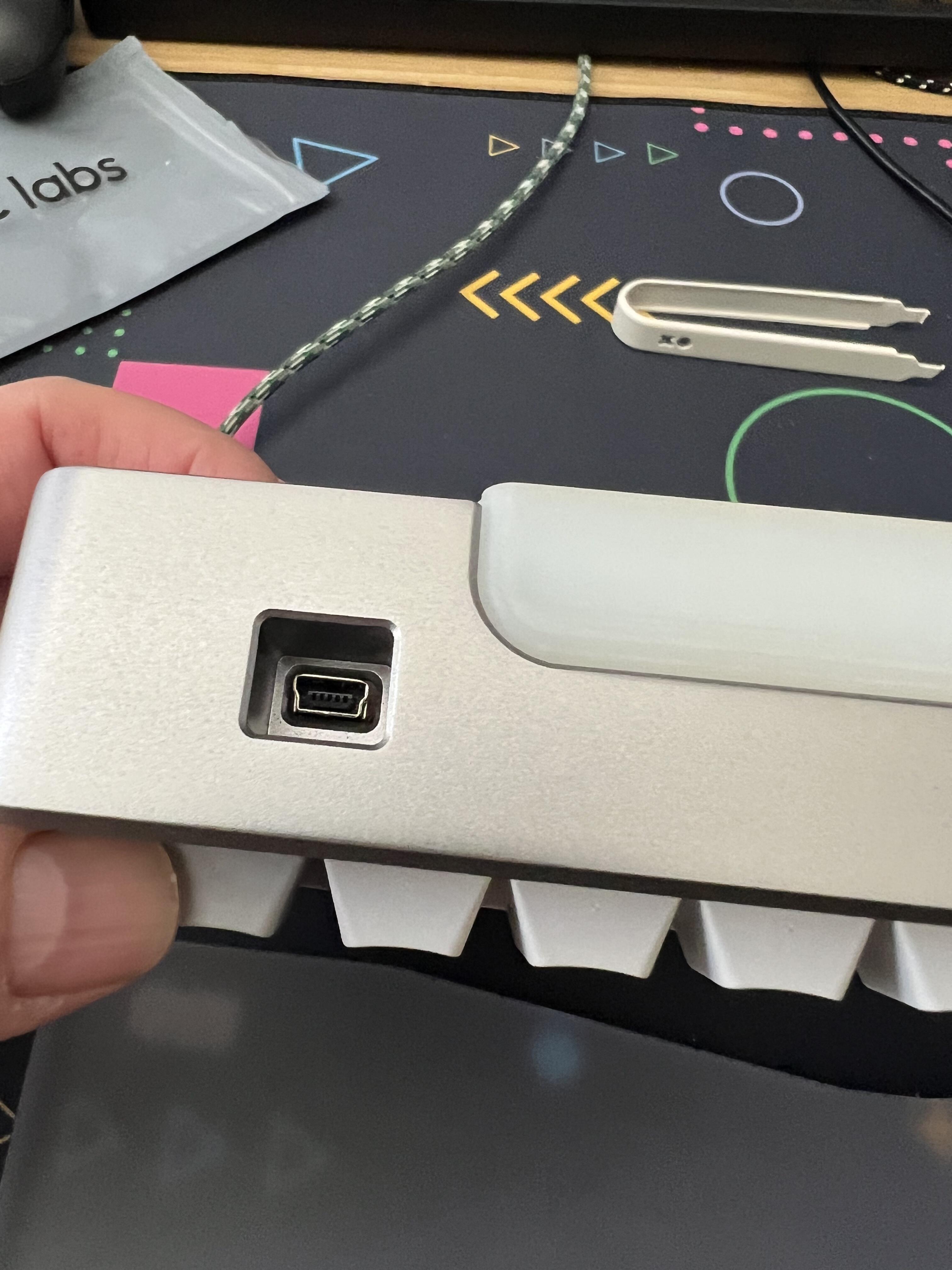
Apart from that, good news, it looks like the Mini USB connector is spot on
I am truly thankful that @Rico decided to pick up this project. This is going to be a great way to revive old m65-As that were either dead or abandoned.
The PCB works flawlessly with VIAL as far as I have tested. I tested with the most recent downloadable beta build of the software. Remapping and LED functions work as expected.
The new plate design does have light bleed along the top and bottom where it shows a slight gap between the plate and bezel, but the new design is a formidable improvement over the original. The plate is FR4 material and no longer attaches to the case near the space bar. I’m very pleased with the typing feel and sound of this new plate. It’s an upgrade for sure.
I didn’t get a chance to try out the 1/2 other than fitment. The plate is designed properly, but I decided to use HG Black linear switches, and they simply fell out of the board whenever turned over. This makes soldering into a 1/2 plate quite the chore. I have a feeling the 1/2 plate will be an even better typing experience. I know I plan to solder one down the road.
I’m even more excited for the hotswap version of this PCB. Just that little added insurance for things like stabilizer wire pop-outs and rattles.
I’m happy as could be with the current iteratoin, but I’m happy to see that @Rico is striving to make it even better.
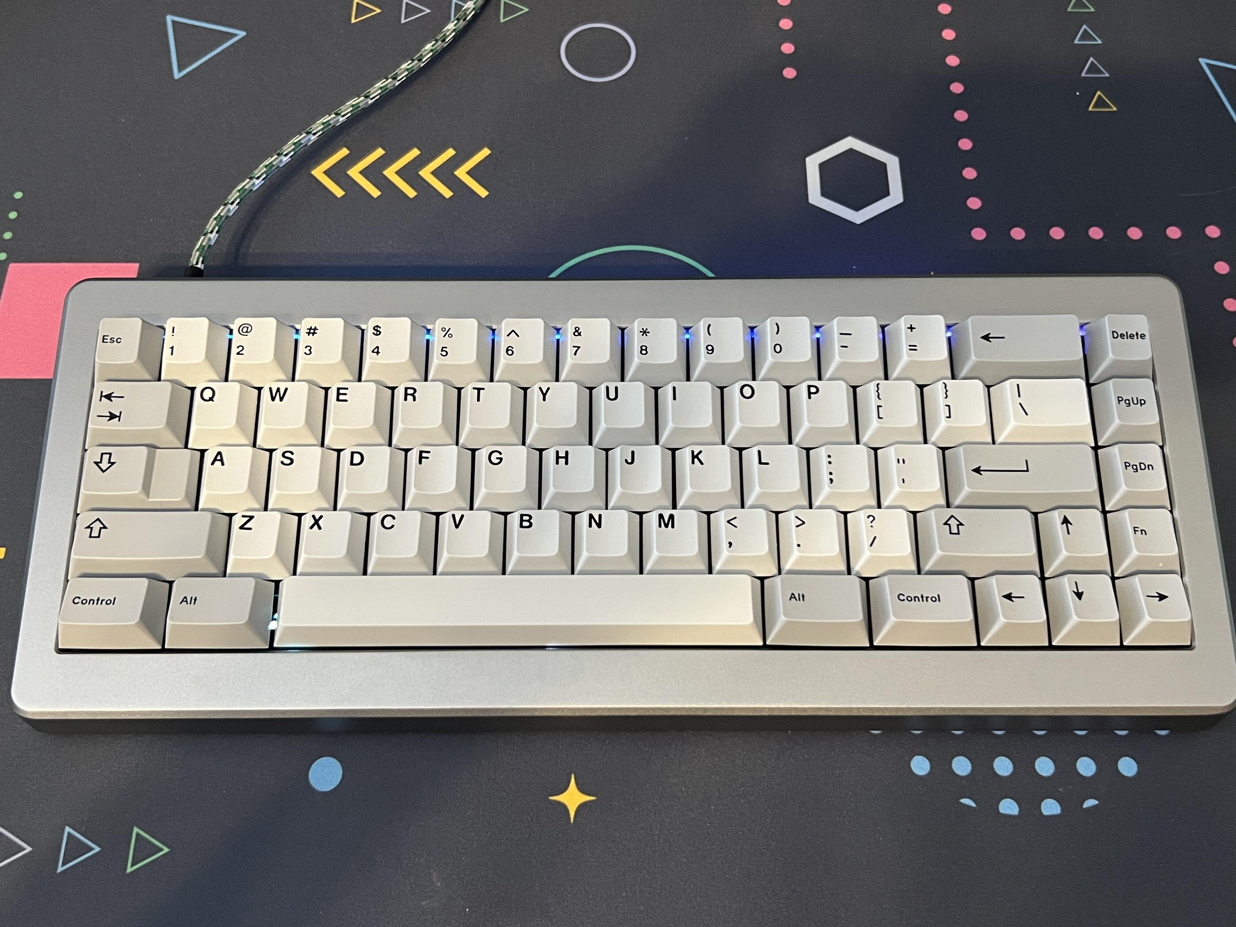
Here’s one of my M65-As returned to life thanks to the Phoenix 01!
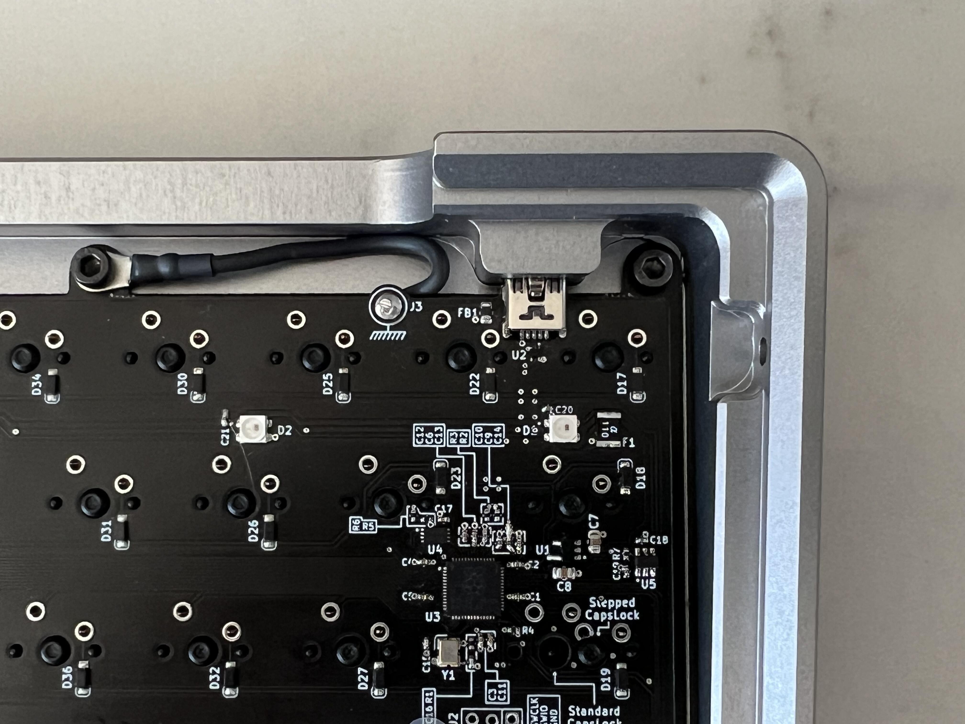
Another great improvement, at least in theory, is that this PCB has a ground wire soldered to the board that connects to one of the mounting holes. So, shock goes to case > screw > groundwire, instead of to the chip. Did I get that right? Anyway… let’s hope this helps with any future ESD problems.
Yes, in theory this should do just that.
Also a few people a long time ago with the official PCB, sticked metal foil between usb connector and case with significant improvements on ESD protection.
This cable does just that, but in a cleaner way.
As for the layout selected for the hotswap PCB, this is exactly the same as the one @pixelpusher selected for his build.
This is not a normie layout, and may appeal to some 65% purists out there
As said @pixelpusher, part the reason why I did not used USB-C is to not have to file the case.
I also proposed to use micro USB connector that would have probably fit, to later refrain from doing it.
The reason is that the connector is slimmer (also the same for USB C) and you’d see a big hole around the connector and worse of all it would not be centered.
The case is designed to fit USB mini perfectly, so decided to keep it
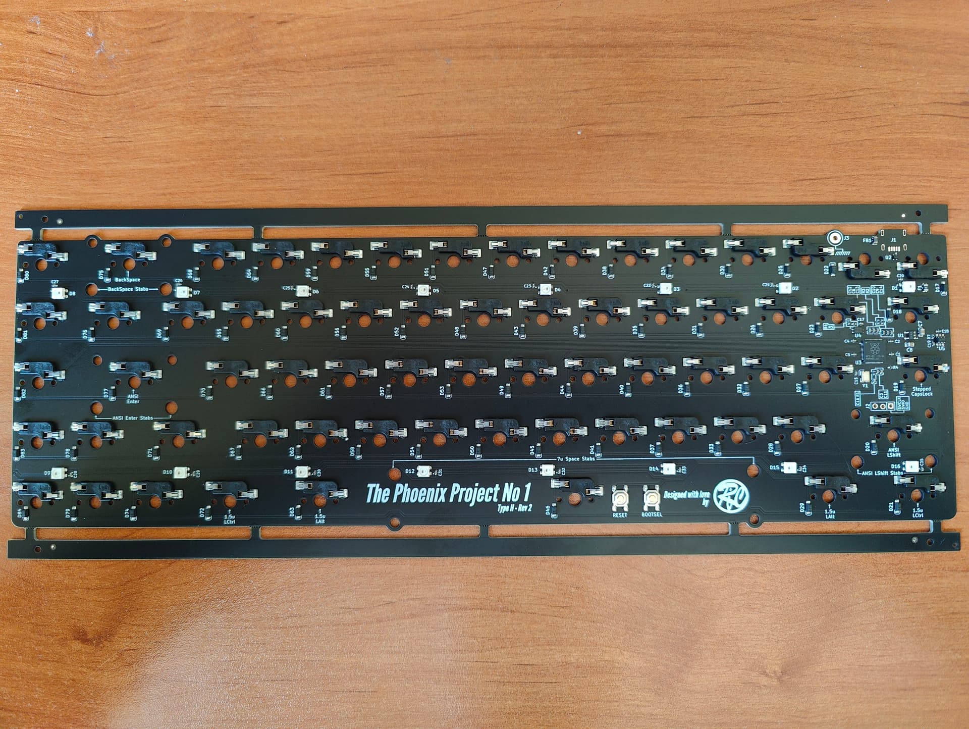
Revision 2 PCBs has been sent to fabrication at JLCPCB !
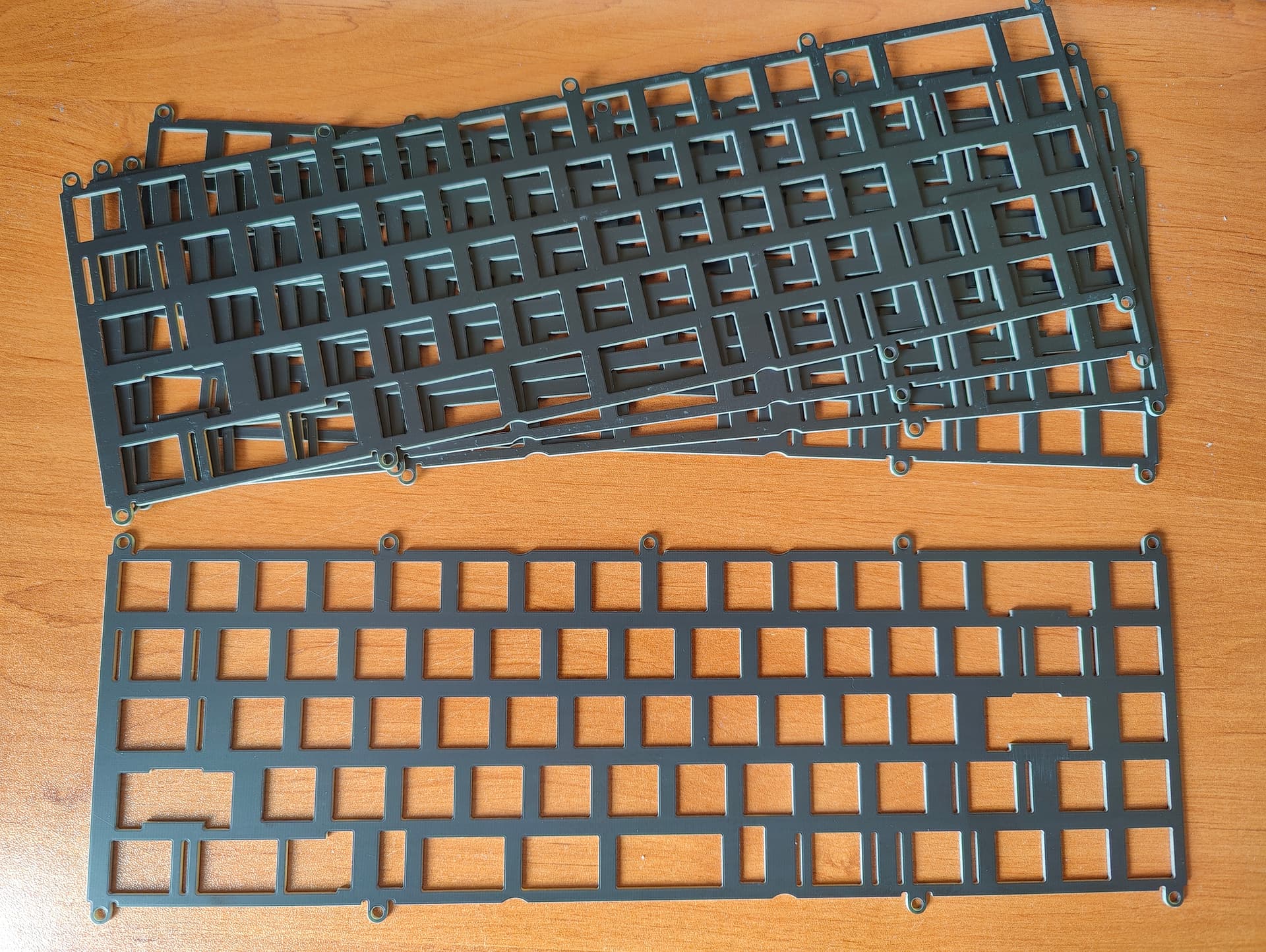
This includes a new full plate design with issues found by @pixelpusher hopefully fixed.
This also includes new Type H version of the PCB, this time with 2 PCBs fully assembled using the new standard assembly service, only the USB connector will be soldered by me as I want to confirm the fitment before committing to let it made it soldered by JLCPCB.
The new standard assembly service that JLCPCB provides is pretty neat as it allows to solder more component types like Kailh hotswap sockets and the RGB leds that I use in my design.
That means that once this PCB will be received and valided to work, everyone will be able to order PCBs on their own without worrying to solder those tiny components themselves
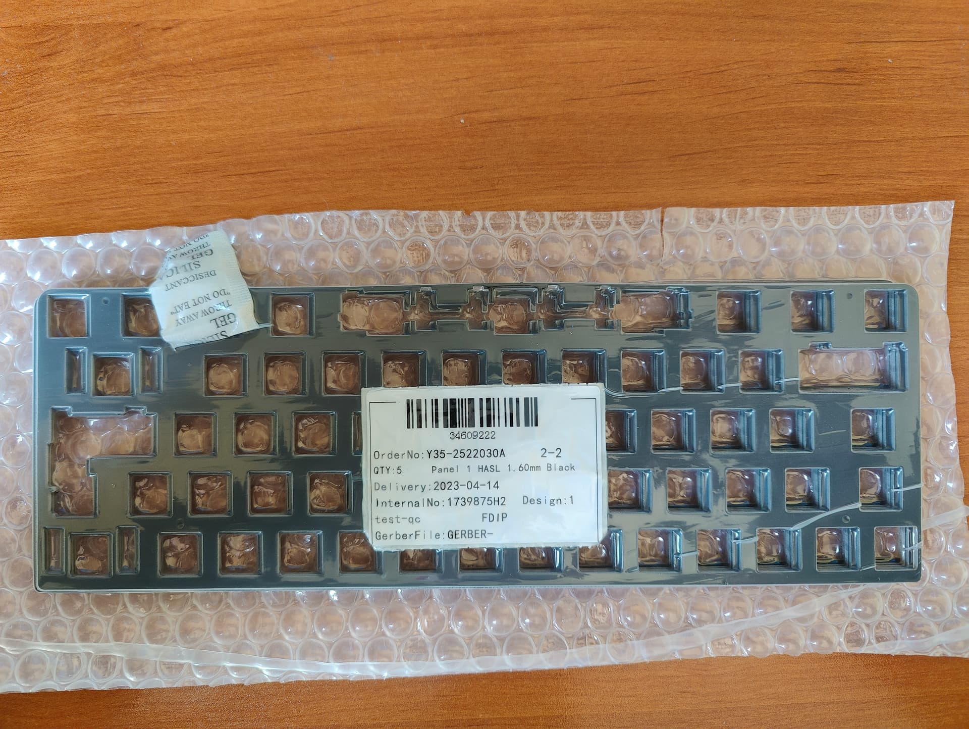
Good news, I have received my 5 Phoenix Project No 1 Type H, all assembled (but the USB connector) from JLCPCB.
And the USB connector fits much less firmly into the PCB, this looks like it should be ok to make it assembled by JLCPCB the next time.
I reached out to the support and waiting for an answer, hopefully this will be resolved nicely.
But this will delay the testing of the new plate a bit …
After having soldered the USB connector on the 5 PCBs, I am happy to say that they all both working like a charm !
And also confirmed that the same firmware works for both the Type S and Type H PCB.
I still saw a little bit of resistance when inserting the USB connector so I will probably tune the through holes positions a little bit again to totally eliminate it.
Once fitment in a proper case is done with the new plate design, I’ll be ready to open source the design.
And I’ll also have 4 Type H PCBs available for people who may want one to revive their own M65-A board
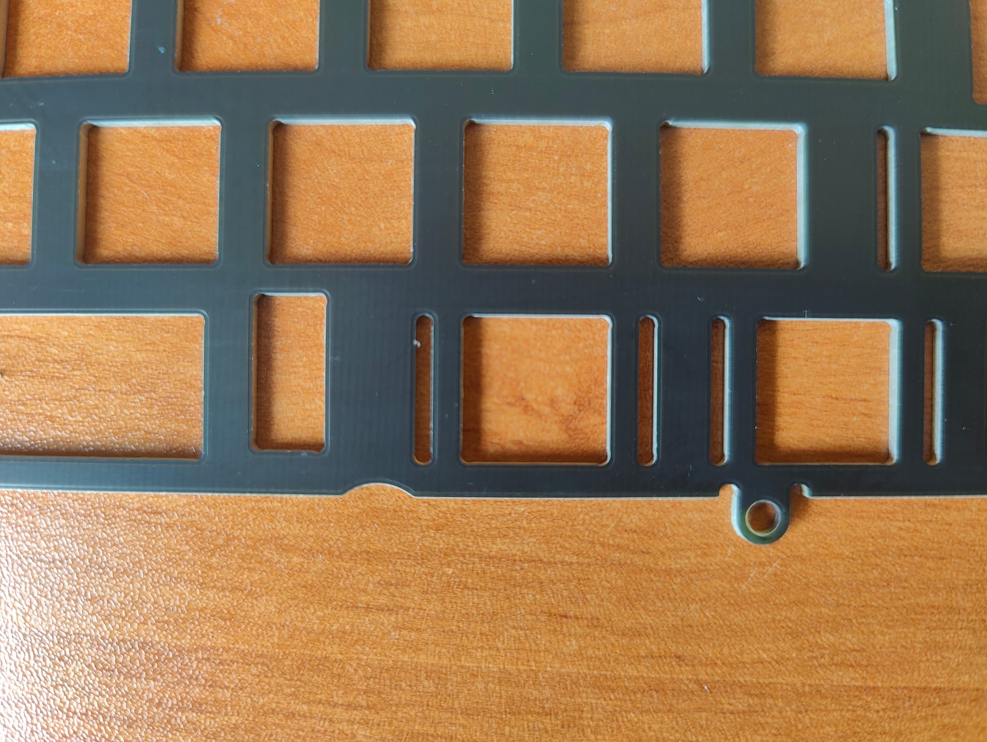
As you see below the plate extend a little bit further to reduce bleeding.
Also the mount holes are significantly thinner, this may help a bit to add even more flex.
This is so exciting! I love following the progress on this project. Sounds like I might even have my grail up and running in fully operational condition come summer!
I slowly started to work on open sourcing the project, so that when fitting of the new plates and PCBs will be validated you will not have to wait long.
The licence I selected is the Creative Common 4.0 Share Alike licence; this one is quite permissive and allow to manufacure and sell Phoenix Project No 1 PCBs wihout asking me permission, only give me tribute for my work.
I first started cleaning the Kicad files, that is remove all/most DRC warnings and a lot of minimal stuff.
And also cleaned any licence conflict problems that may arise.
Notably I used a few 3D models outside Kicad source tree, all of them have to comply with the licence I intend to use to provide the PCB design.
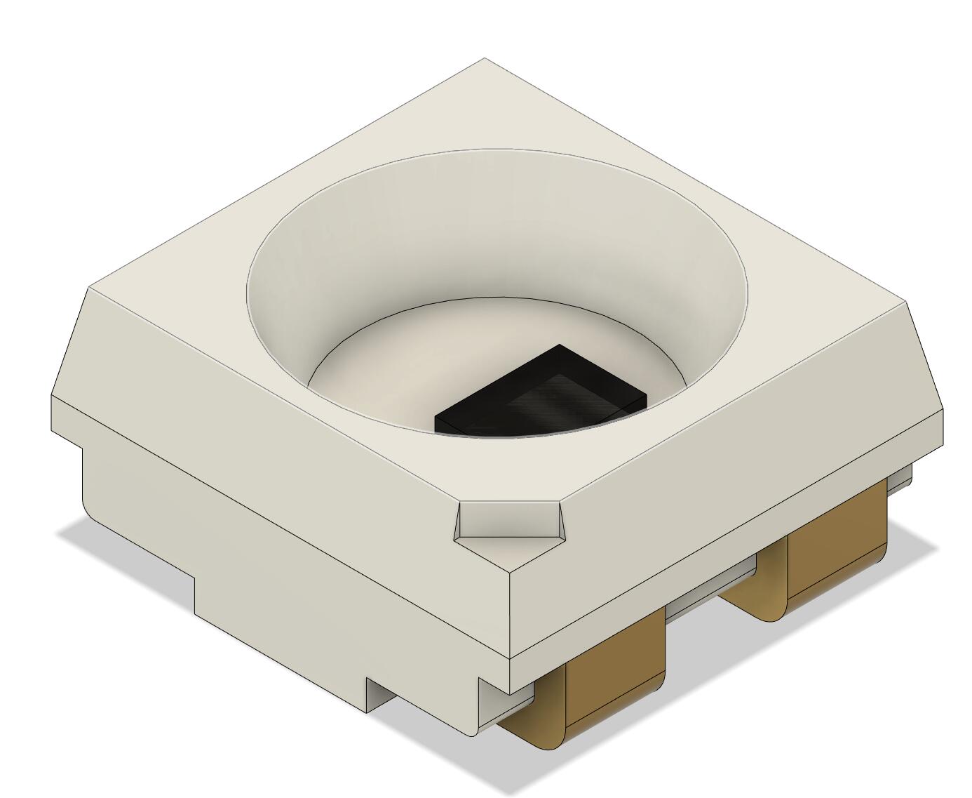
And I had a problem with the WS2812B Mini 3D model; it was taken from a github project that had no licence indication on it, so it means that I can’t use it without asking the permission to the project manager.
Could have asked him, but found faster to model a replacement from scratch using Fusion360.
So here it is:
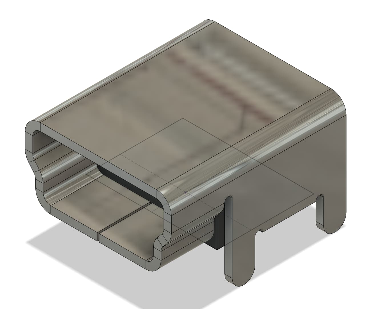
Also could not find any model for the USB housing I used, so modeled a 3D object also.
This one was more intricate and interesting to do as I tested for the first time the Metal Sheet feature of Fusion360
It is not a perfect reproduction but pins positions and general housing dimensions are accurate.
By doing that I could find errors in both the USB housing datasheet and in my Kicad foorprints so it was worth the trouble !