I’ve mostly been a lurker here on KeebTalk but after being encouraged to share in one of Manofinterest’s streams I figured I would go ahead and put this post together. After typing this up I’ll give a warning here. This ended up being pretty long so if you’re interested in a TL;DR I threw one at the bottom.
I’ve always been a bit of a keyboard enthusiast but it was at the beginning of the year that I started wading into the deep end. It also seems to be when a bunch of other people leapt into the hobby as well because it was a real pain in the ass to find anything in stock and things were selling out quickly when they did get posted. To make a long story short, I got my hands on a Tofu65 and was off to the races on trying out different switches and tuning stabs. I also finally sat down and trained myself to type on the home row and type without looking down at the keyboard.
The logical next step was to join a group buy for a nice custom. Originally I was quite happy with a normal layout board and was looking around for a 75% but it was around that time I started to notice I was getting a bit of strain in my wrists from typing on the home row. This changed what I was looking for and I started looking more seriously at Alice style boards. One of the issues with the Alice style boards however was the lack of both a function row and arrow keys. I use both on a regular basis for work and also use multiple computers at work so I didn’t want to get used to doing my job with layers at home only to get back to work and get frustrated at the non-programmable keyboards there.
Another issue I had was I’ve never typed on an Alice layout before and with everyone in lockdown for the foreseeable future I figured there was only a couple ways I was going to get to try it out. I was either going to have to commit to a $400+ board without trying it out before hand (and probably have to settle on losing my function row at least) or I was going to have to make something myself.
At the time I didn’t really have a game I was hooked on and my wife had picked up a couple TV series I was uninterested in watching so I had plenty of spare time to burn. I decided to get my feet wet and at least learn how to customize an existing pcb design. At the time I figured it might be easier to edit an existing design than make my own.
I downloaded the Arisu files off github and started poking at it. I realized I couldn’t really make heads or tails of it. This was partially because I couldn’t figure out how to turn off what I now know was the ground plane for the front and back of the pcb.
It was around this time I got pointed in the direction of the ai03 pcb design guide and the ai03 discord. These were immeasurably helpful resources even if the design guide was a little outdated being centered around USB Mini B instead of USB Type C. I cannot say enough nice things about the people in those design channels and I would have been very lost multiple times without them pointing me in the right direction.
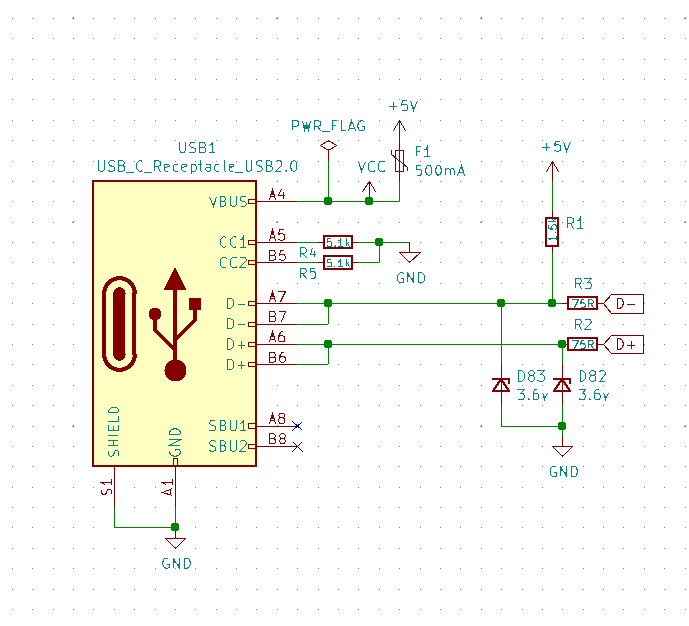
After poking at the Arisu design some more I decided it would just be easier to start from the ground up. I wanted the layout to be much closer to the Alice layout anyways and I was in this for the learning experience. So using the ai03 design guide as a starting point I started working on my schematic in KiCAD. I must have gone through 30 iterations of USB C schematics before I fully understood what was needed or what the phrase “5.1k pulldown resistors” even meant.
As I was going through the design process I was also thinking about how I hadn’t soldered anything in over a decade and even then it was just XLR and TRS ¼” cables. This thought nagged at me in the back of my head until I decided to take a page out of Coseyfannitutti’s book and make the entire project through-hole. This would give me plenty of things to solder and get my skill up to at least passable and I figured if I messed one up I had four more boards to get it right. I also had zero experience flashing AVR chips and I sort of looked forward to learning. I’m not sure my future designs will be through-hole like this though, as it definitely adds a lot more work, but I was off to the races.
This choice informed which parts I would select and thus began another schematic revision. I used CFT’s Mysterium as a reference for the schematic which helped a ton. I did make some minor changes like getting rid of the LED power indicator among other things. It was very helpful to have some guide rails while doing my first project like this and if anyone else is looking to take on a project like this I’d recommend designing something similar to an already functioning keyboard so you have something to look at when you get lost or confused.
Once I had the schematic all worked out I figured the hard part was over. Now all I had to do was lay out the parts and connect the dots right? Hah! Boy howdy was I wrong about that. Normally doing layout for switch footprints in KiCAD isn’t a big deal. You put your layout together on KLE and export it as an SVG and then import it in PCBNew. The problem is KLE and KiCAD do angled objects differently and when you import a layout with keys at angles in PCBNew everything comes in as a jumbled mess and it’s almost 100% useless. If anyone is curious this doesn’t seem to be a problem in the nightly version of KiCAD so if you’re lookingg to work on an Alice style pcb I’d recommend installing the nightly as opposed to the stable version.
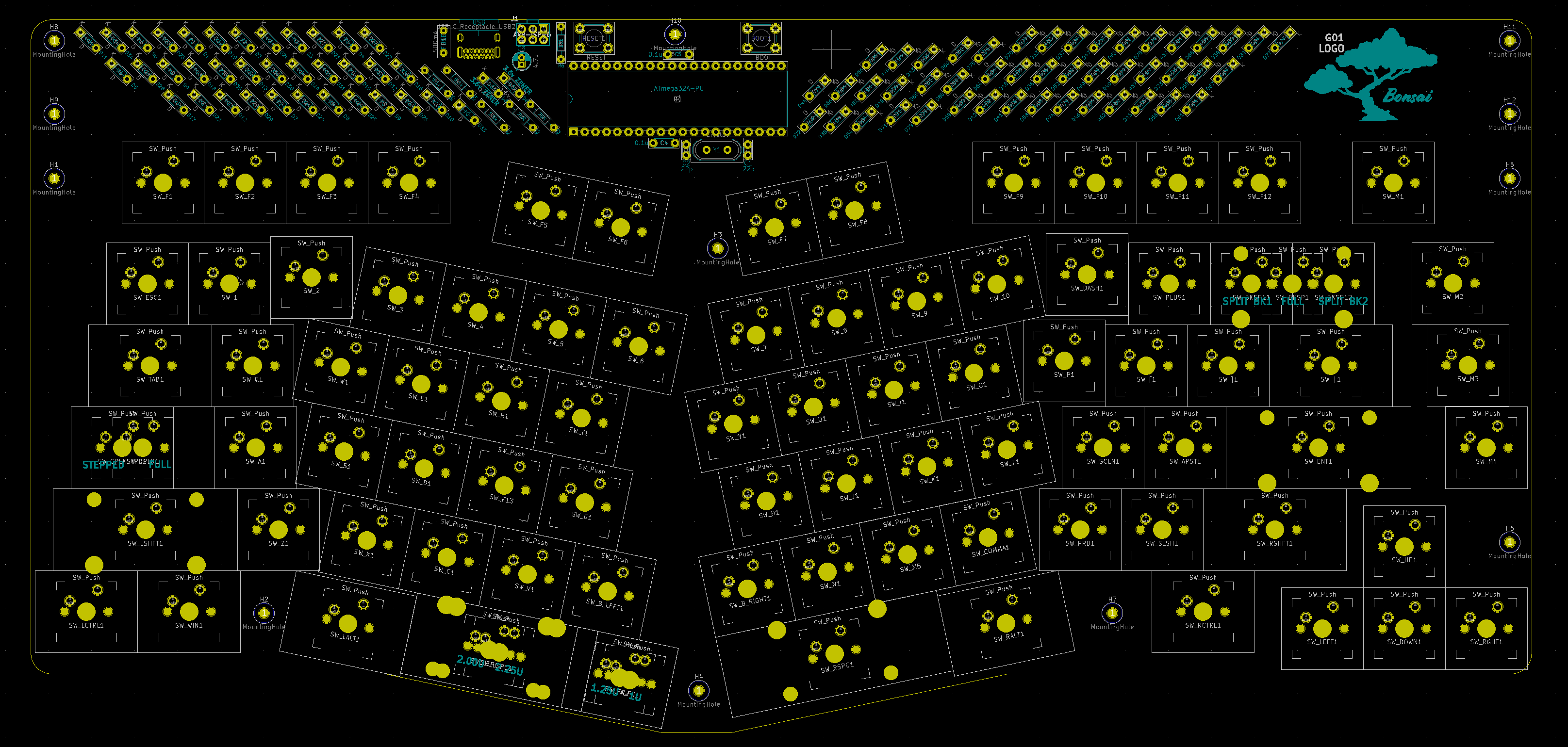
It did give me the layout for the keys that weren’t angled though so I had a starting point. I had to free hand the rest of the layout as there wasn’t an open source Alice layout pcb design out there when I was working on it and the Arisu was different enough to not be helpful (Spoilers: I did a pretty good job if I do say so myself). Eventually I got the switch layout done but I was still a bit worried I had gotten parts of it wrong and the keycaps would bind once I put them on the switches. I decided to trust myself and move on.
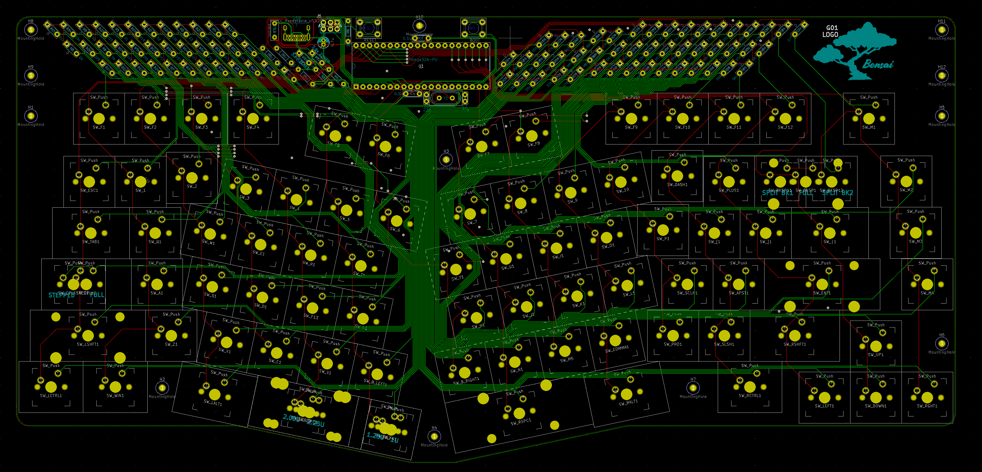
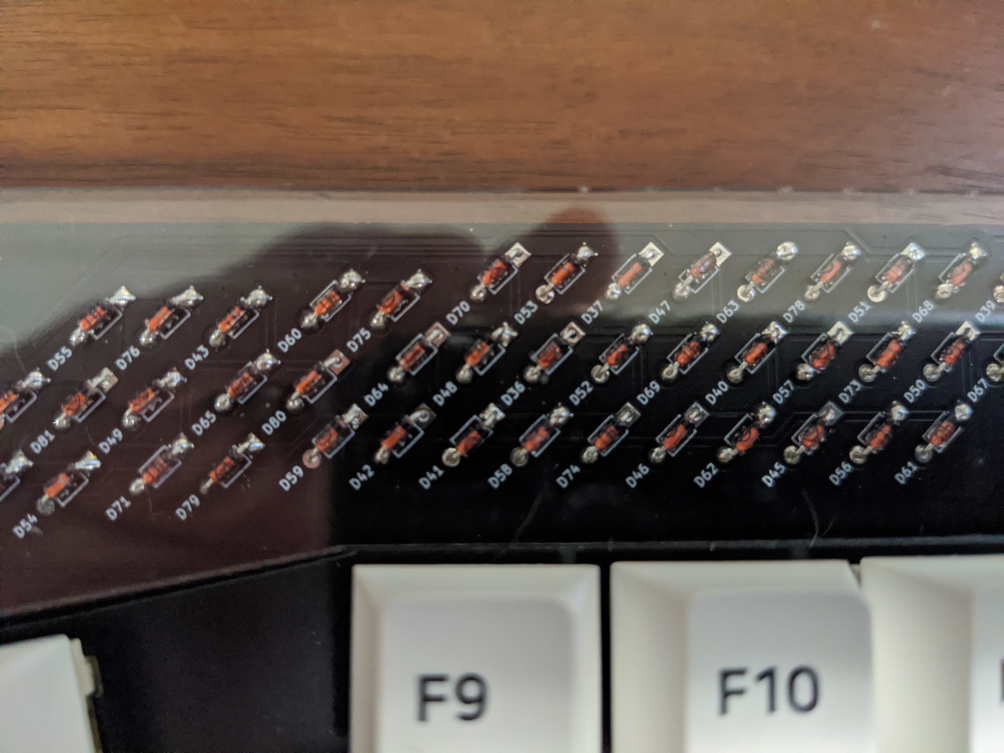
Now came the layout for the rest of the parts. The big challenge here was making something that I felt looked appealing. I tried a bunch of different layouts and settled on an angled diode bank to go with the angled keys. Looking back on it now I may have put the USB C connector in a different location if I were doing it all again but this was my first project so it is what it is.
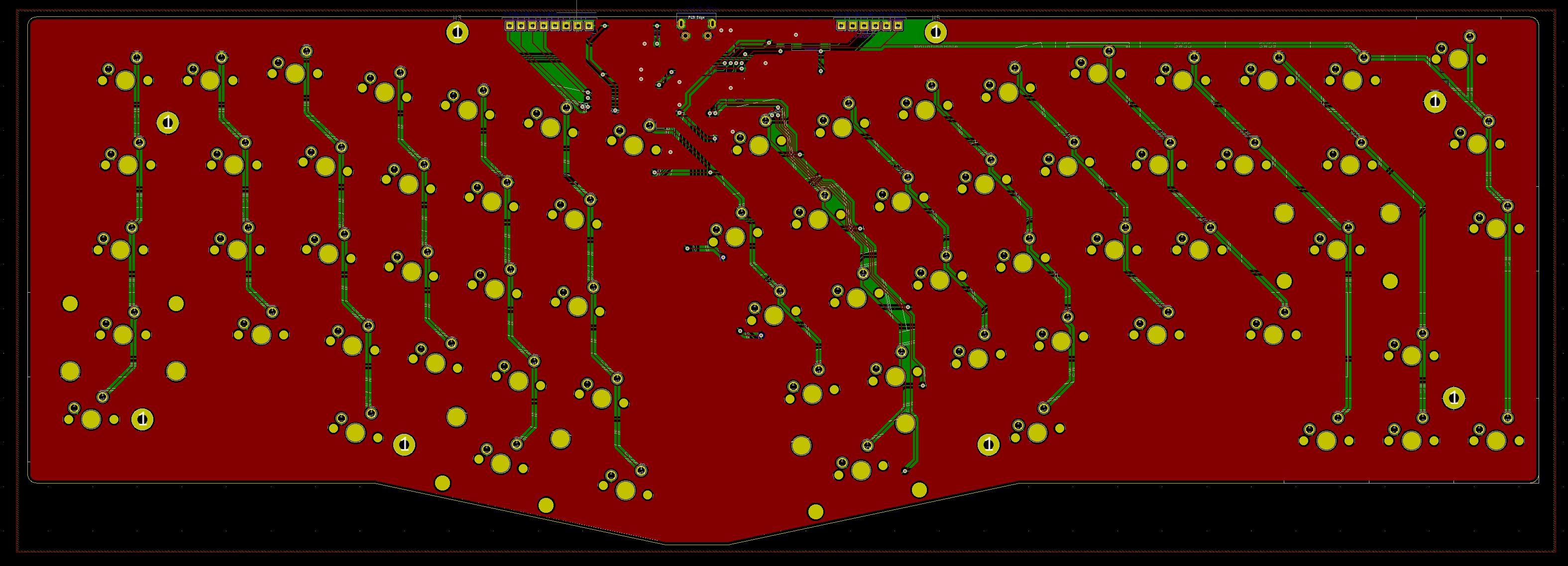
All I had left to do was connect everything. There’s a phrase that was used more than once on the ai03 discord that I’m probably butchering here with my swiss-cheese memory – “the last 20% of the work takes 80% of the time” and they were not wrong at all. Pathing traces in a logical manner takes way longer than you think it will. KiCAD loves to ignore whatever obvious path you’re routing your traces on and will loop your traces around random components or just shoot all the way to the top of the pcb and then back down to where your mouse is.
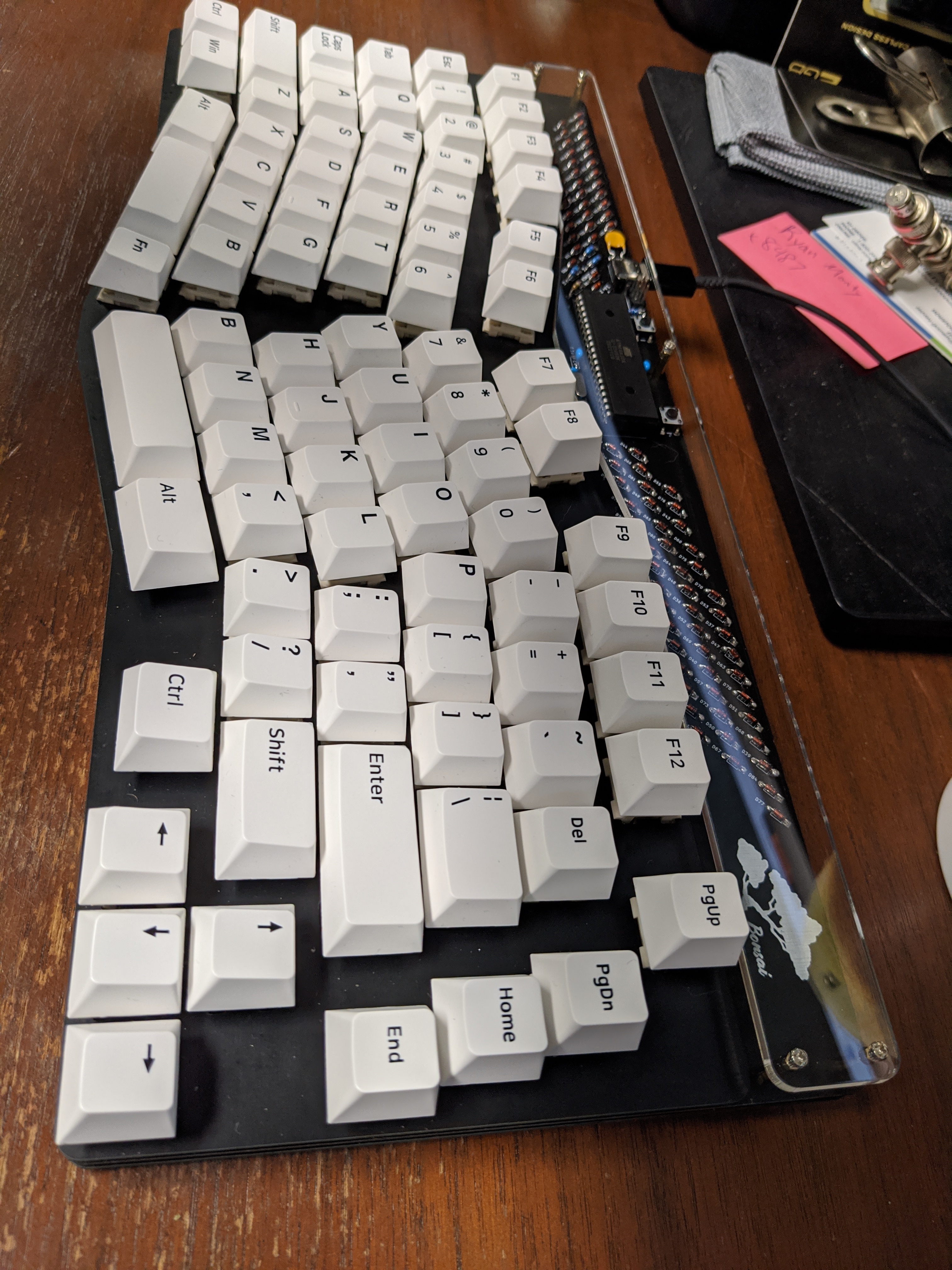
While running the traces on the board the name of the keyboard solidified for me. Originally I was working off the name “Willpower” because it was taking willpower for me to finish it and it was a bit of a riff on the name of CFT’s Discipline. But as I started running more and more of the traces up the middle of the back of the board the design started to look more and more like a tree to me. So I thought about what sort of trees require effort and time to create and ended up with the name “Bonsai”.
After checking to make sure there wasn’t another project named after the Japanese art of making kawaii trees I named the board.
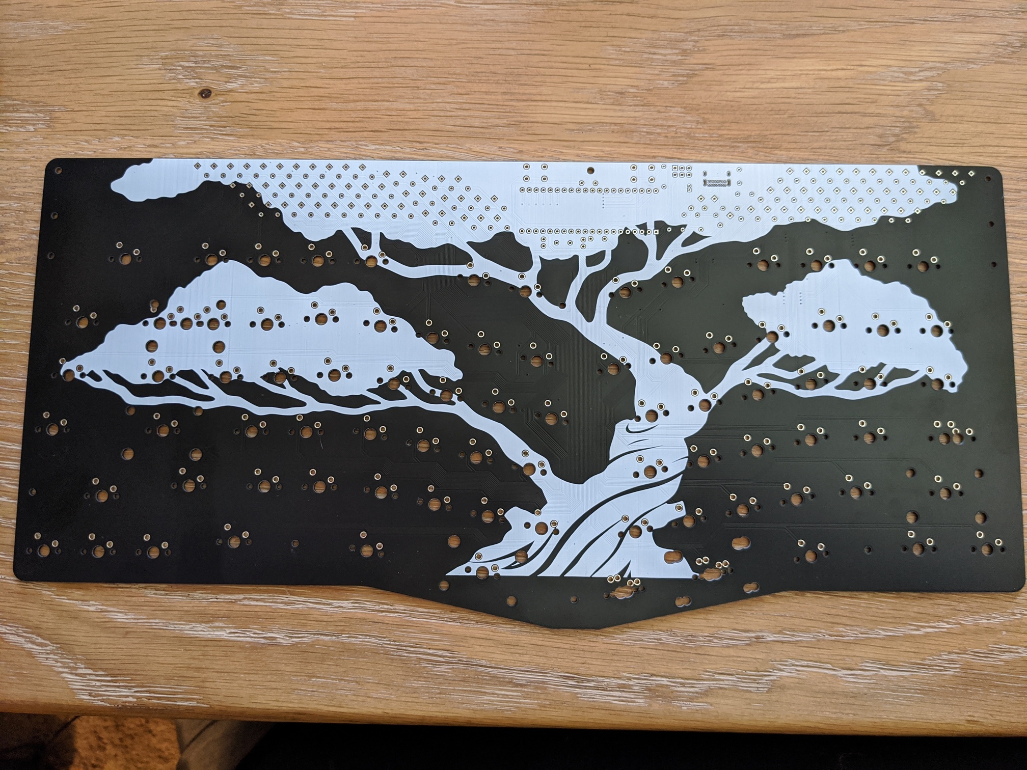
As I was finishing up the design I started cajoling my wife into making a custom design for the board as she’s a graphic designer and photographer by trade. She made me these beautiful tree designs for both the little badge on the top of the board and a large one to put on the back. I don’t think I’ll do too many large screen print designs for my pcbs in the future as there was obvious streaking in the larger filled spots. I will probably revise the base plate and front badge to be exposed copper instead of the screen print they currently are and just ditch the giant one on the back in favor of putting layout labels on the back as well as the front.
With everything finally laid out and connected I ran the DRC error checker and had to fix a few things like having vias a little too close together. Also I figure if you’ve read this far I’ll throw in a little tip that if you decide to make your own pcb definitely listen to ai03’s guide where it suggested saving connecting the rows and columns to pins for when you’re laying out all of the traces. This will allow you to choose logical pins for your boards layout and not leave you running your rows and columns under each other in some sort of mad scramble to match the schematic you made ages ago.
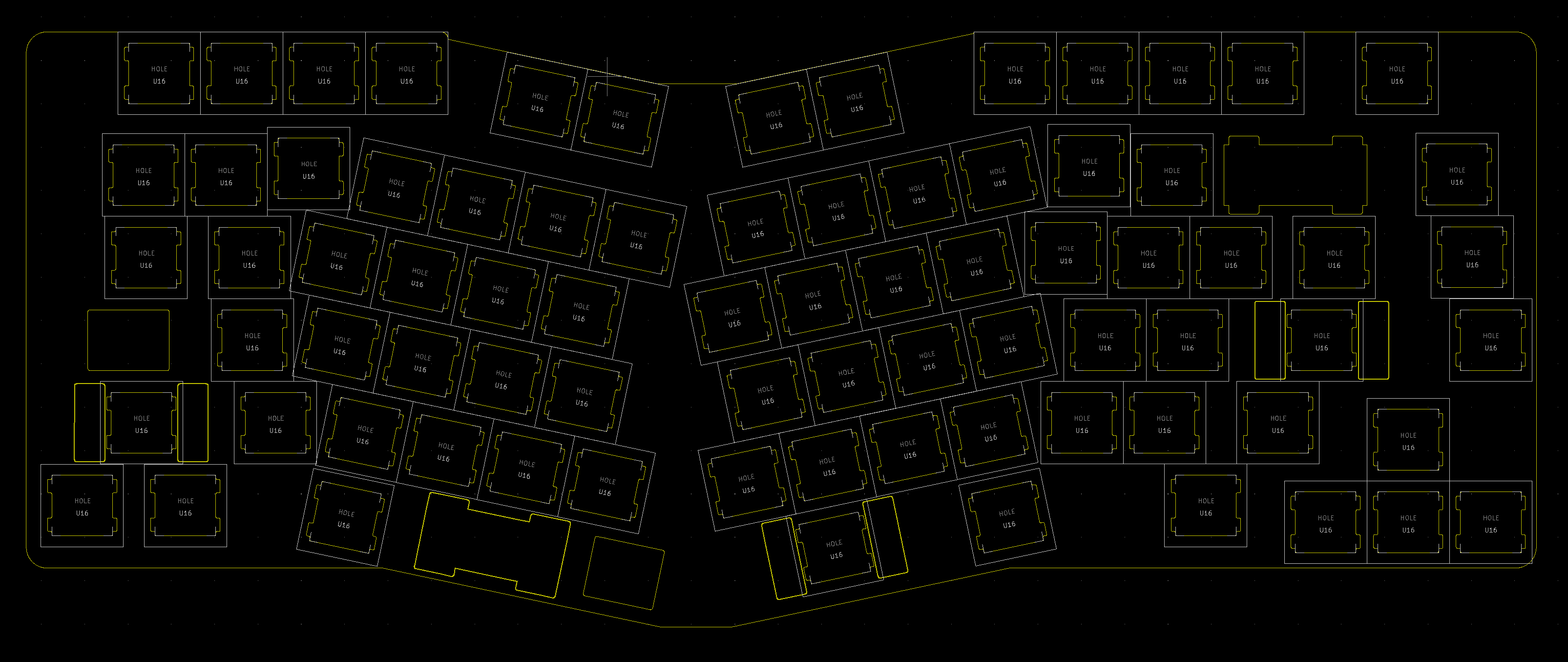
I pushed my design to github and asked people on the discord to take a look. Some people took a cursory look and said they didn’t see anything amiss so I pushed forward. I made both a switch plate and base plate design in KiCAD. Once again if this wasn’t an angled layout I could have made plate files from KLE but since I hand did parts of my layout I needed a different approach. I found a nice MX switch plate footprint, copied my pcb design to a new file and replaced all of the switch footprints with the switch plate footprints.
I was now ready to shop the design around and see what the cost would be to get a prototype run of the design done. Let me tell you on cost it wasn’t even close. JLCPCB blew everyone else out of the water. I think the next closest was PCBWay but they cost $100 more on just the pcb and way way way more for the pcb, base plate, and switch plate. It ended up costing me $95 shipped for 5 prototype boards plus 5 base plates and 5 switch plates. All in all not too shabby but this was not including the cost of electronics needed to turn the pcbs from useless plates into sweet keyboards.
I put in an order for all the parts I’d need to make all 5 keyboards with Mouser ($71) and I definitely made a mistake in the ordering process. They had an option to send things to me as they came in stock or to save on shipping and send it all in one package. I had assumed this meant they would set aside parts as they came in stock and once everything in my order was filled they’d ship it out to me. BZZT! Wrong. Instead I ended up waiting a month and a half watching different parts cycle in and out of stock without my order shipping which was frustrating because about halfway through that wait time I had already received my pcbs.
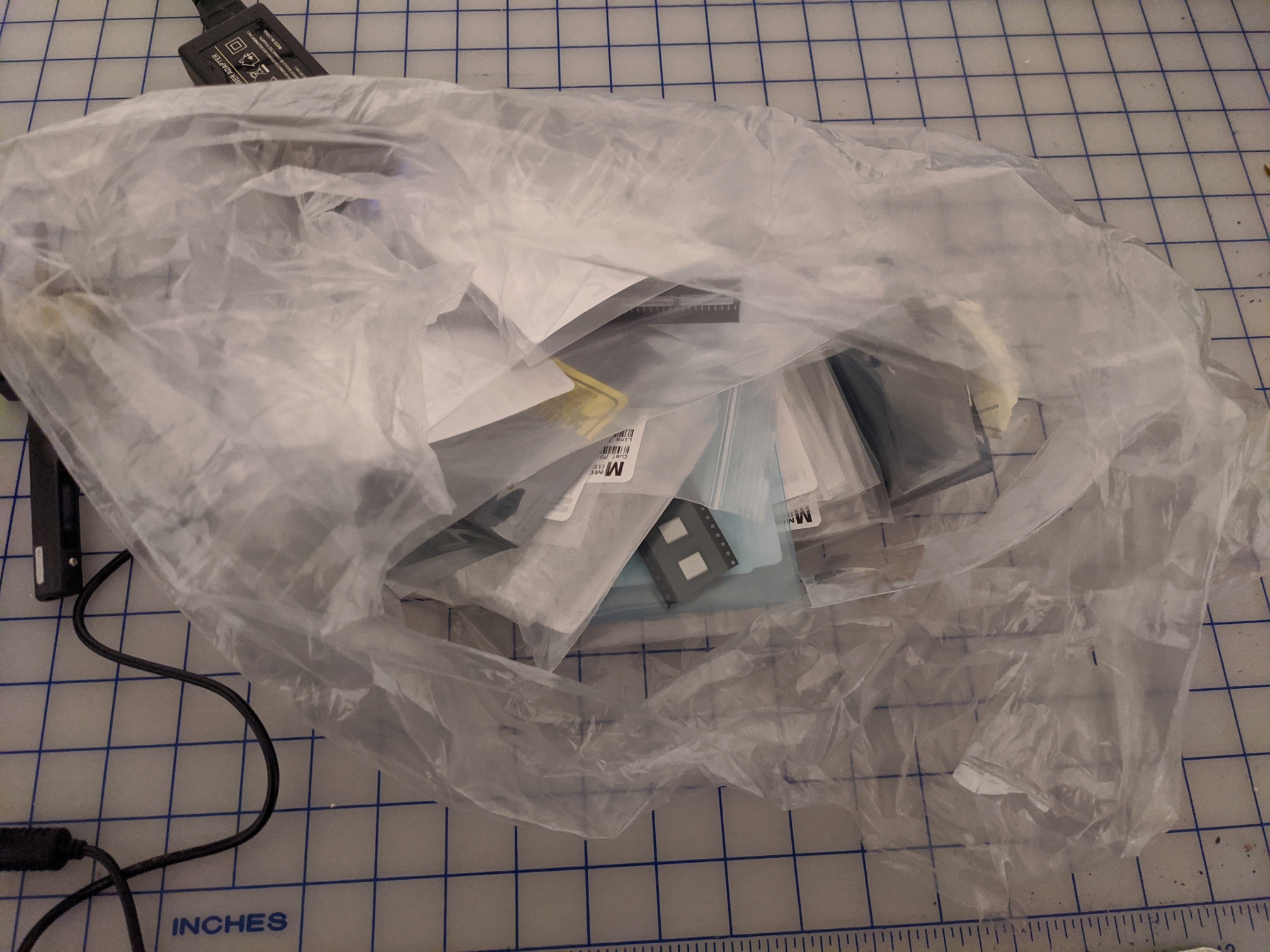
In the end I contacted Mouser and had them change it and I swapped out a part because the 4.7uF capacitor I originally chose was going to take months to restock. It took almost another whole month to get the shipment to my place and it almost didn’t update on the tracking at all which had me constantly wondering if Mouser had even gotten my order shipped out. In the end I got a big plastic bag full of electronic goodies.
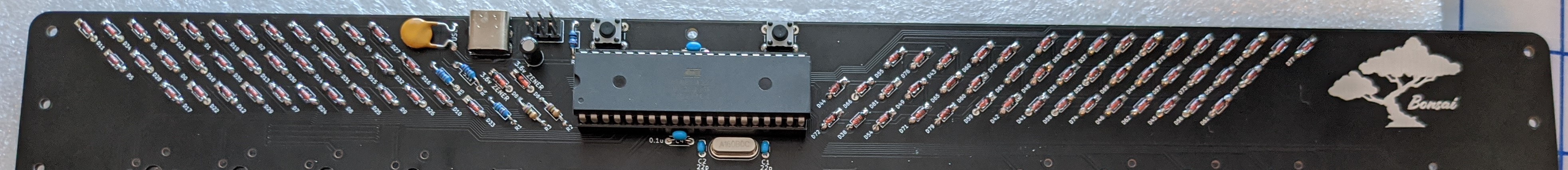
So I got to work soldering and learning how to handle smaller electronics. It was way easier than you’d think but there is definitely still some finesse involved in getting a perfect joint. Soldering all the diodes made the switches seem like a cake walk and I’d advise anyone that has watched a fair bit of keyboard building streams but always feel worried they’ll mess up a solder job to just give it a try. It’s pretty easy in the grand scheme of things as long as you aren’t aiming for perfection with each solder joint. I certainly have a handful of diodes that have little solder balloons on the front side and it still works just fine.
After getting all the electronics on the board I sat down and started plonking away at getting the USB bootloader on the MCU. I used the same one CFT used for his boards as I was using the same flashing device and MCU. I would say the most important thing is don’t bother trying to use WinAVR like the bootloader tells you. It’s outdated and requires a patch from 2007 that they never fixed. Hell, WinAVR hasn’t been updated since 2010. Use MSYS2 instead. Where WinAVR failed me MSYS2 did the trick and allowed me to compile and flash the bootloader.
During all the waiting for parts I also worked on putting together both QMK and VIA support for the keyboard. It was the first time in a long time that I attempted to do anything that looked like coding. It was a bit easier than I was expecting and watching MechMerlin’s streams helped quite a bit in this regard. So shoutout to MechMerlin for helping me figure out how all the pieces fit together and get some proper hex files put together. I haven’t bothered to try and commit my keyboard to either project yet though as I’m not sure I’ll do anything with it beyond this prototype run unless people really like it and want one for themselves.
Anyways once I got the bootloader flashed to the pcb it was very simple to set the board up for flashing and flash the hex to the MCU. I had some weird errors trying to use QMK Toolbox to flash the board. It kept giving me VID and PID errors from avrdude. So instead I once again busted out my trusty MSYS2 and went to the QMK source directory and ran a good old “make bonsai:split_bksp:flash” and voila my board was flashed with the layout I wanted.
I haven’t tested the VIA portion yet because apparently VIA doesn’t support media keys on ATmega32A chips at the moment and I like having the volume controls bound on a layer.
After confirming all the switches registered with a set of tweezers I went back and soldered all the switches in. After that I slapped some keycaps on it and went to town. An hour later I decided I wanted to put a different keycap set on and POP went my right spacebar stab as I took the cap off. I tried desoldering only some of the switches but eventually just gave up and desoldered them all. Desoldering sucks. Afterwards I replaced the stab with a less busted one and soldered the switches back in. I’ve been using it at work for the last few days and I’ve been pretty happy with it.
Now I know I like this layout and would buy a keyboard with this layout I also kind of want to design some cases for it and have some prototypes made. I guess that will be my next quarantine project. I’d like to make a polycarb case for it but I have no idea where I would find a manufacturer for that. I’ve only ever dealt with metal manufacturers in my area through work and I’m not even sure if they have the detail oriented skills to create a nice case. If anyone has any suggestions for polycarb case manufacturers I’m all ears.
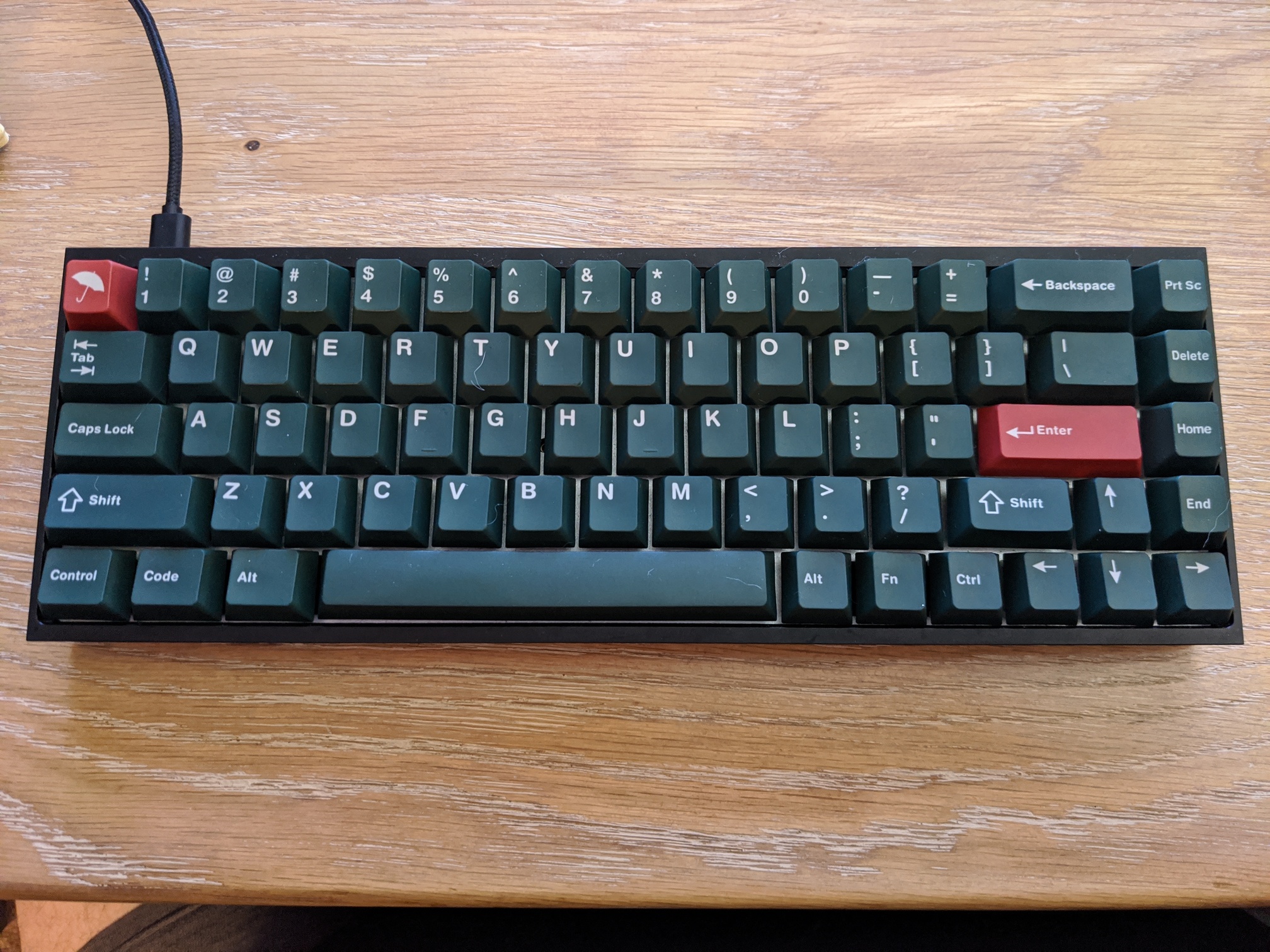
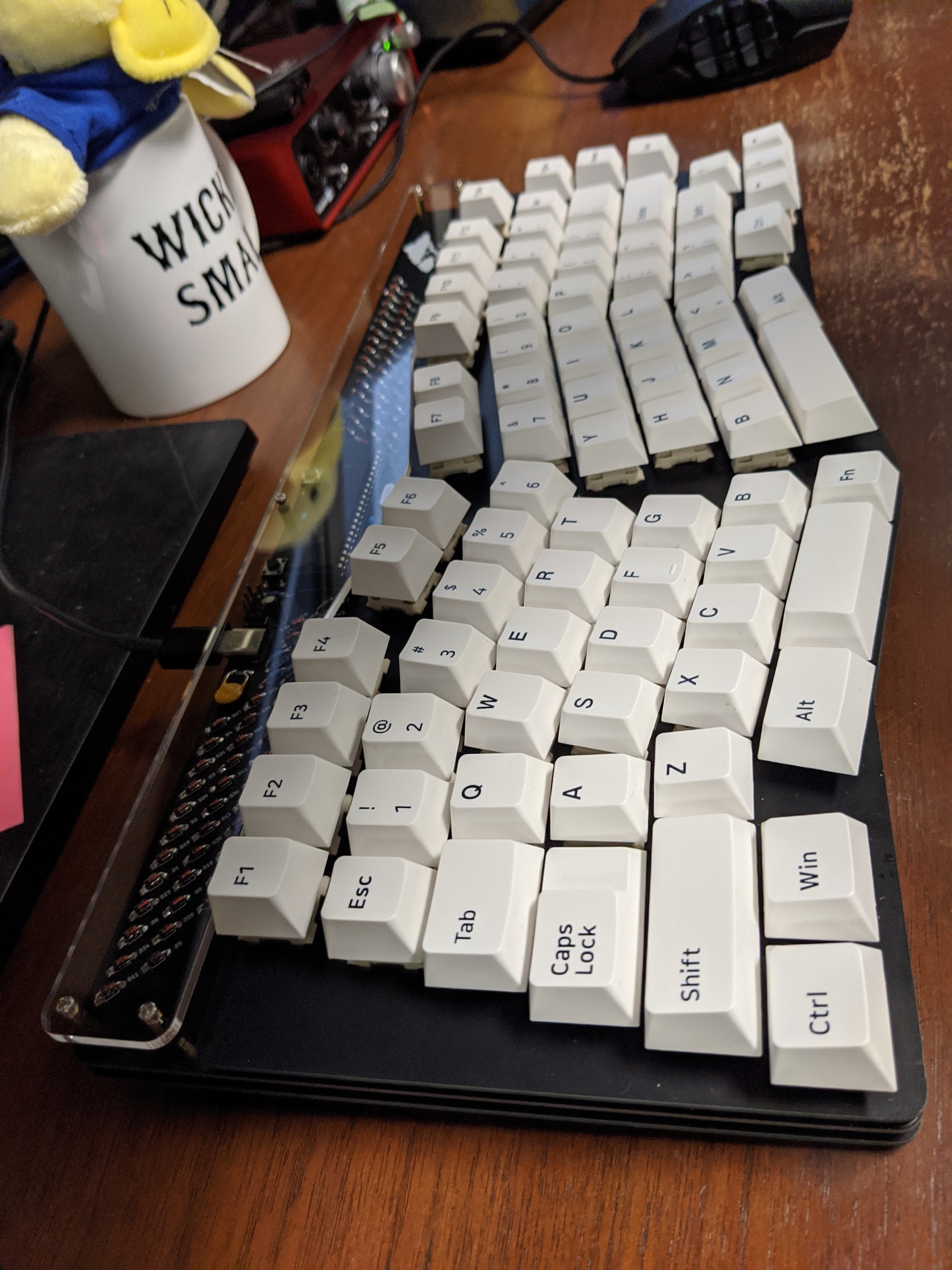
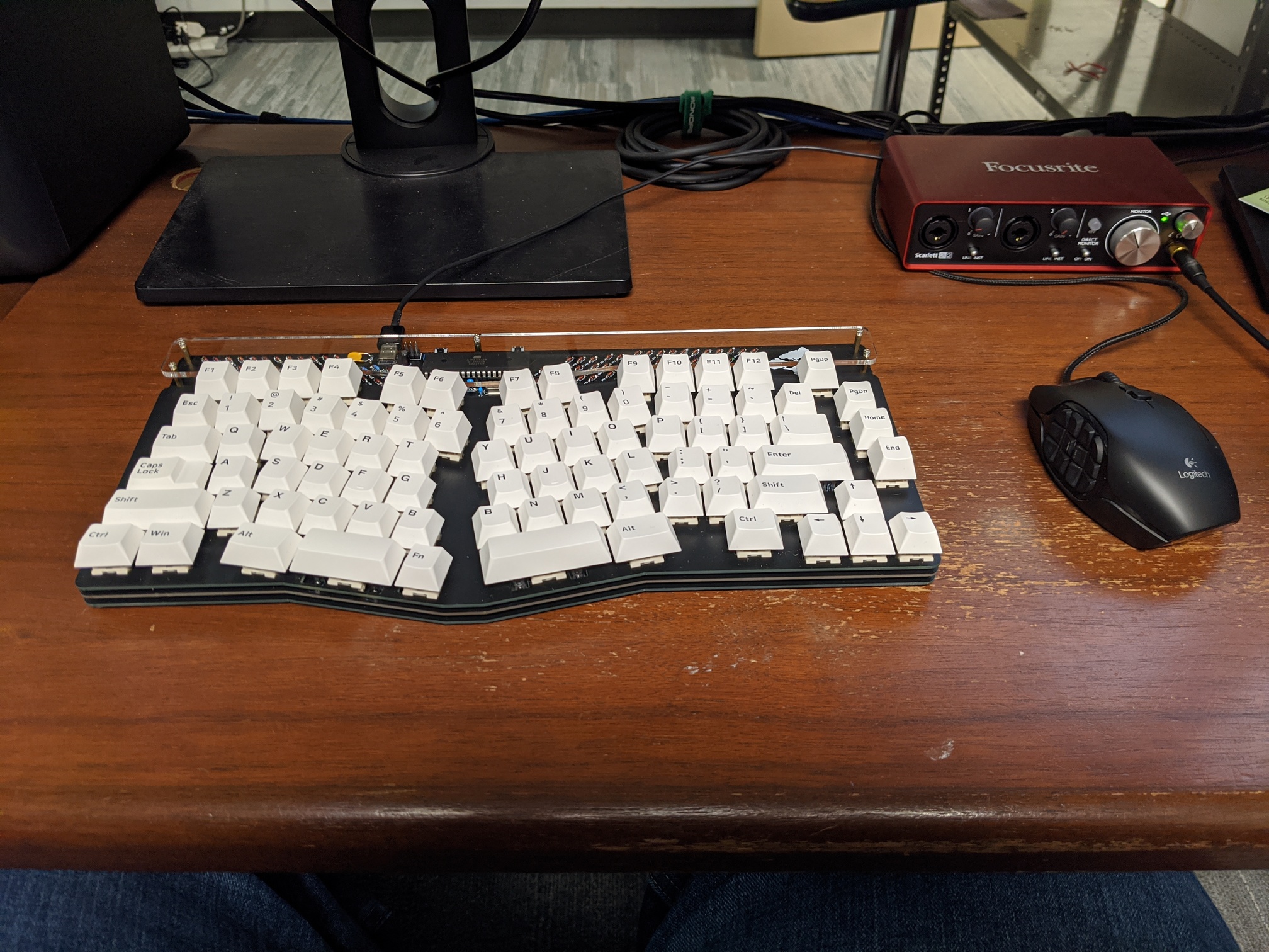
So now that I typed out that huge post here are some pictures of the finished product!

For those looking for a TL;DR: I wanted to test out the Alice layout without spending $400+ on a board I wasn’t even sure I would like. So instead I made my own with the help of the ai03 discord, MechMerlin, and the keyboard design guide ai03 put together.
If you want to check out the project for yourself you can find it here: GitHub - Retne01/Bonsai: This is a THT 75% take on the TGR Alice layout.

