I’ve had it in my head for a while to build a MX-compatible replica of an Amiga 600 keyboard, for use with modern PCs. Because the 600’s layout isn’t anything standard, I’ve thought it would require me to either hand-wire it, or design my own PCB. Efforts on both fronts have proven fruitless in the past - tutorials on making QMK firmware wind up being woefully out of date, or the instructions called for getting output from the abandoned Keyboard Firmware Builder website, and I hit a dead end. I’ve got enough half-built electronic debris from those past would-be builds that I’m in no mood to just add to the pile again.
The Amiga 600 (not my photo):
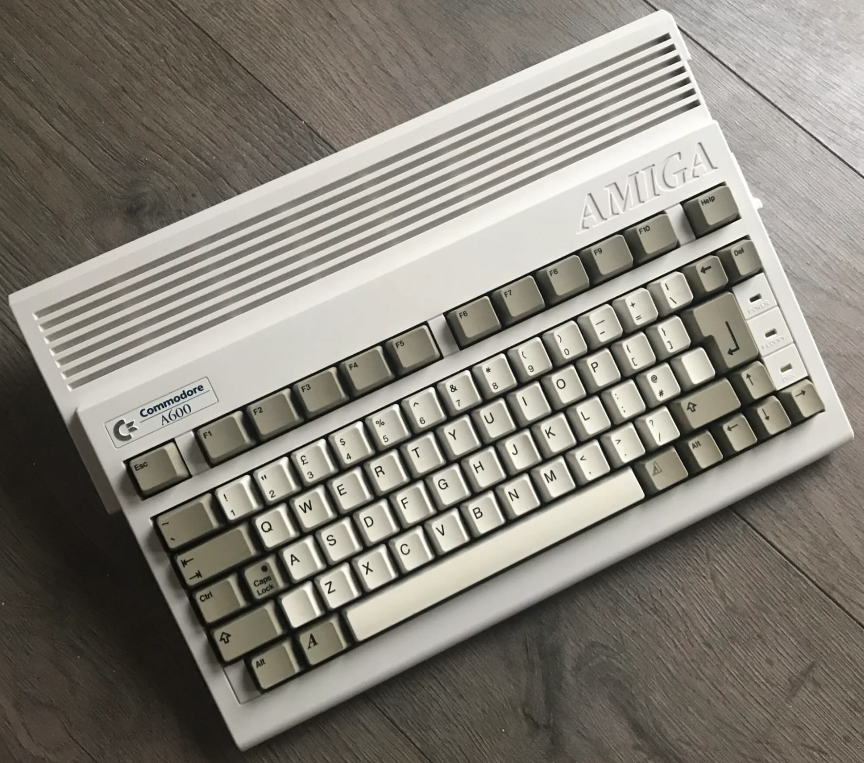
But! The Amiga 600’s layout isn’t that out of date. There’s a bit of dated weirdness to it - really long tilde and tab keys, a whole top row of 1.25u keys, etc. But it’s basically a 75% board, with part of the right column and the lower leftmost mod blocked off. What if I could find a pre-existing 75% PCB and block off the appropriate keys to make it look very similar?
I was familiar with the CannonKeys Obliterated75 PCB already, since I used it in a stacked build a couple years ago. While CannonKeys’s own boards never have ISO support (shakes fist), the PCBs they make for them do. (All Amiga 600s were in an ISO layout, with two keys unused the US just left blank.) The top row will still be all 1u, and the 8u spacebar is now a more standard 6.25u, but those are minor concessions to modernity, and necessary if I’m going to use an off-the-shelf PCB.
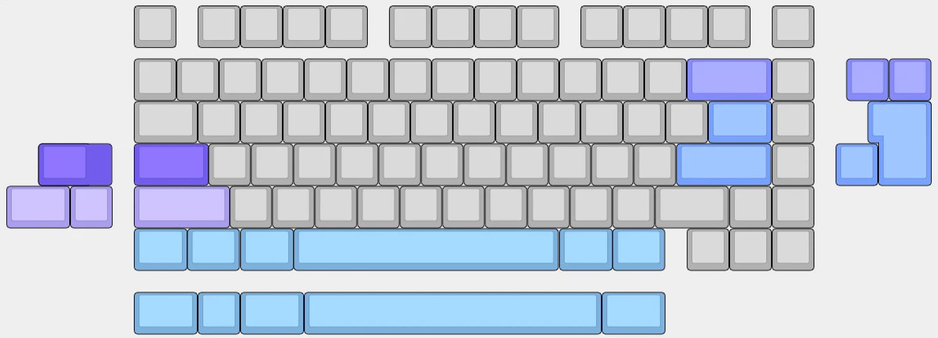
The Obliterated75’s supported layouts:
I don’t have access to a 3D printer or much in the way of CAD skills, so this will be a sandwich board. I’ll need to get the layers laser cut, ideally out of ABS if I can find somewhere offering beige. I’ve only ever ordered from SendCutSend and Ponoko, and SendCutSend only stocks black ABS, while Ponoko doesn’t even offer it as a material. I could live with a light grey acrylic if I had to.
For caps, I have MT3 Susuwatari laying around, and it has the right keys to cover everything relatively accurately to the original 600 layout, plus Amiga logo keys to boot. (Dev/tty might work better, but since the International kit is permanently out of stock, I’d wind up short a few critical keys, like Enter.)
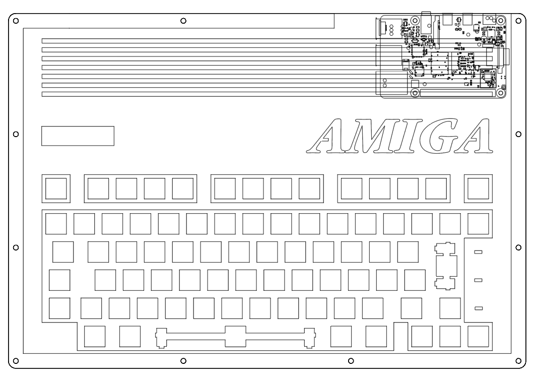
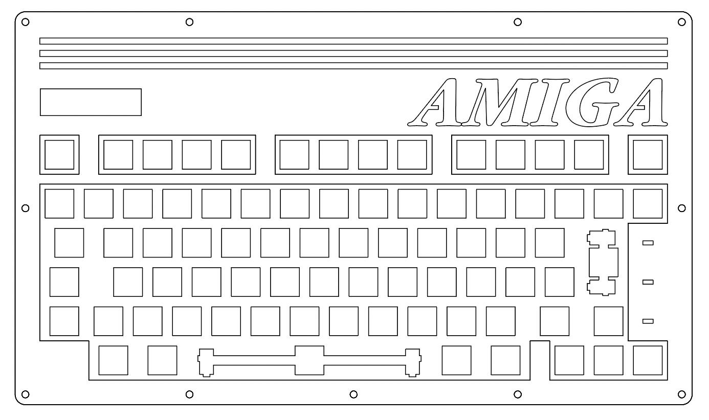
Here’s my initial design:
And a quickie color mockup of how it’d look with Susuwatari:
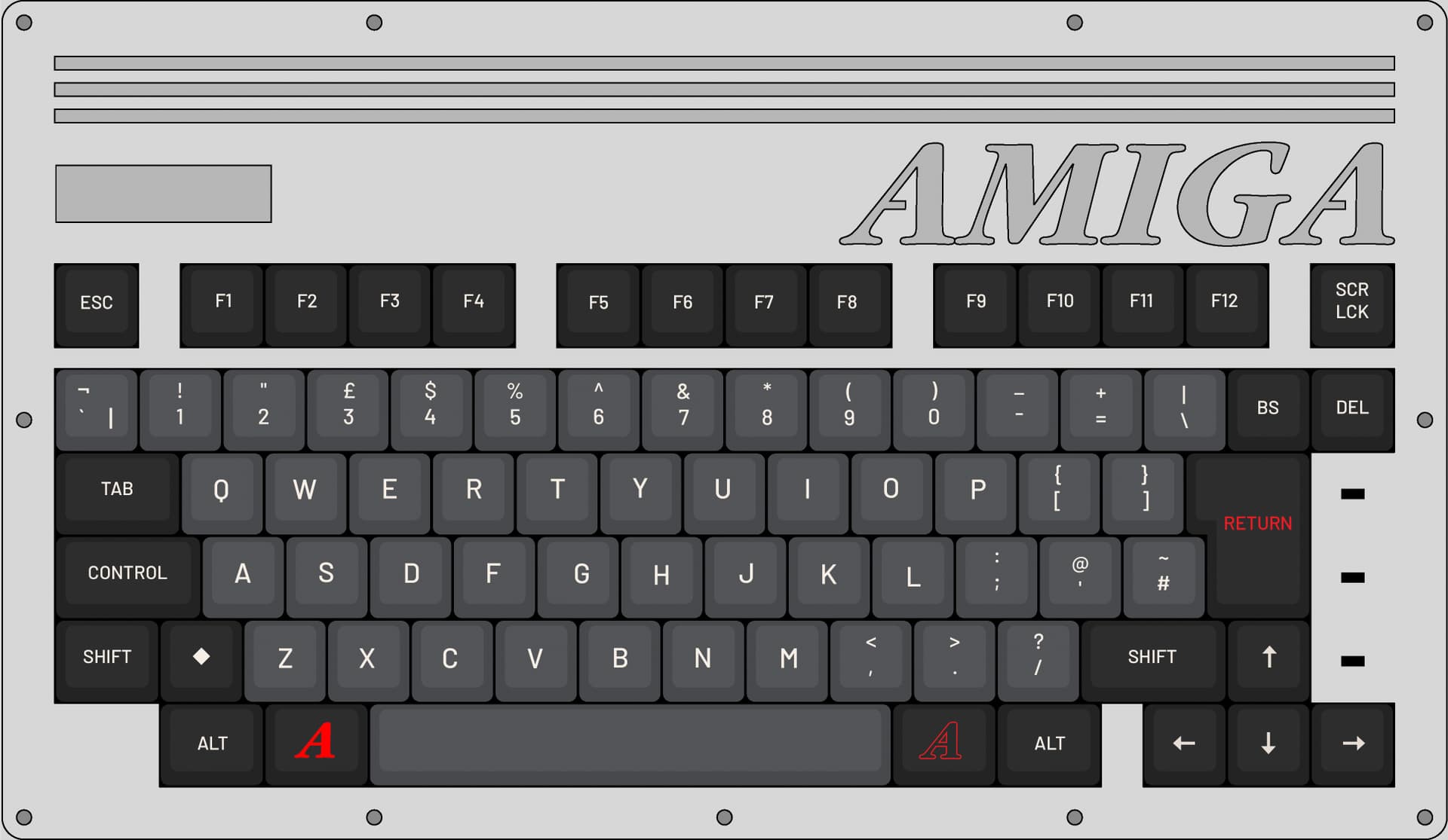
I sized the rectangular logo cutout on the left side to accommodate a replica A600 case badge I found on Etsy. The lettering on the right side has been modified to add bridging to the gaps in the A characters, for the laser cutting.
Here’ the top layer on its own:
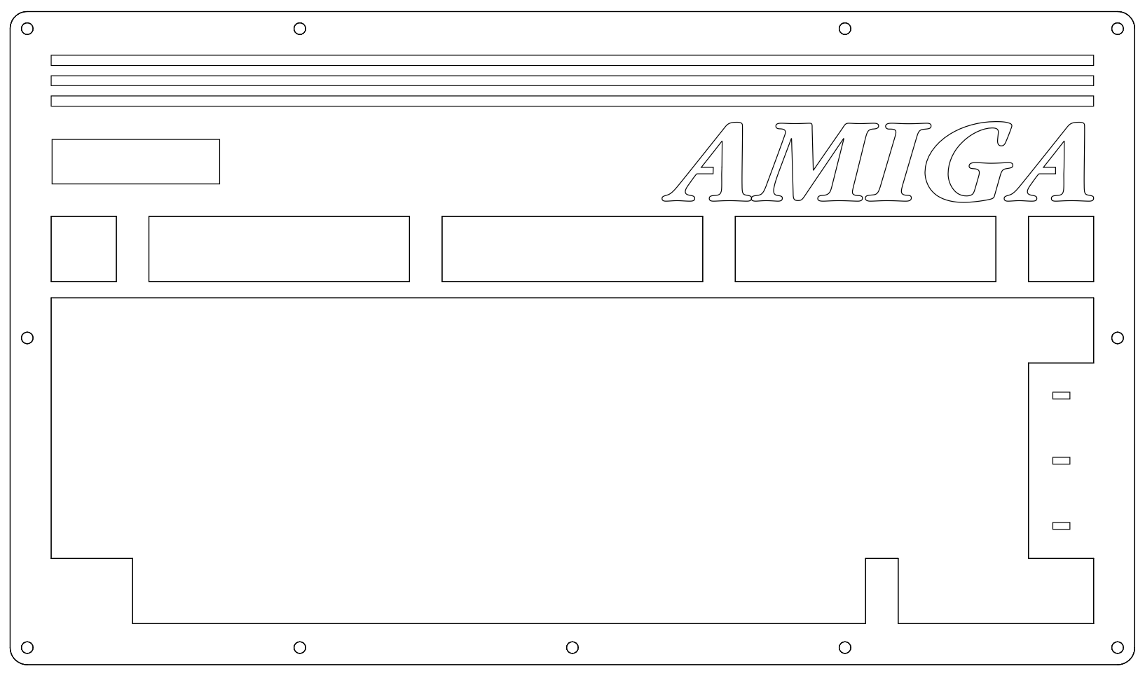
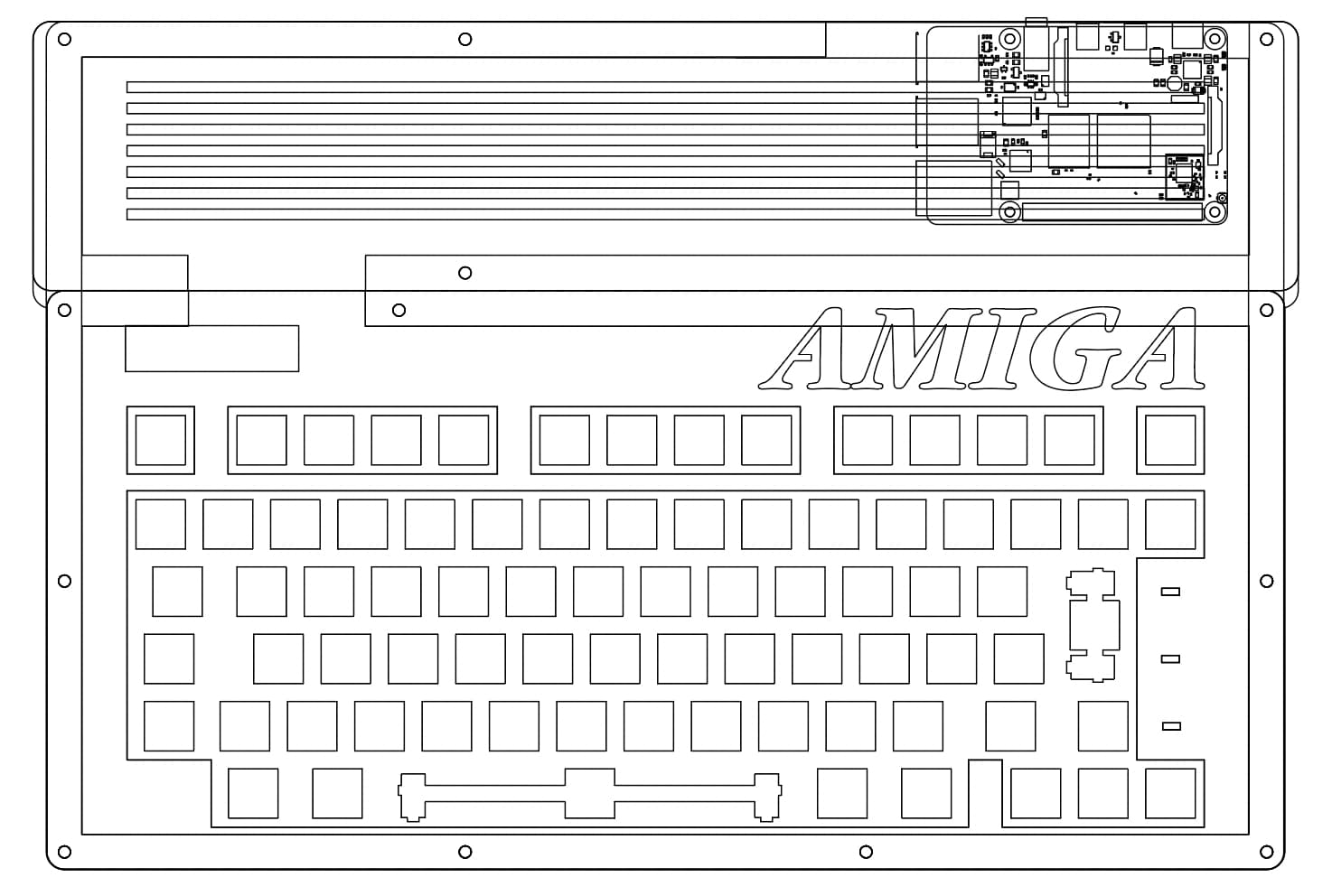
The layer below it has the cutaways filled in, so the case badge can rest upon it. I might make this a different color than the layer above, so the top layer’s lettering stands out more:
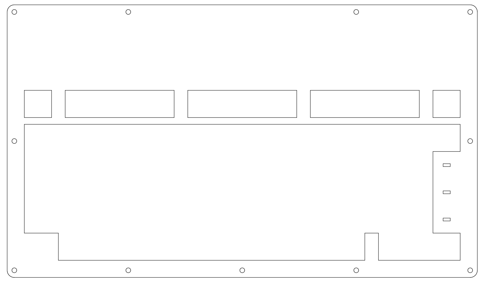
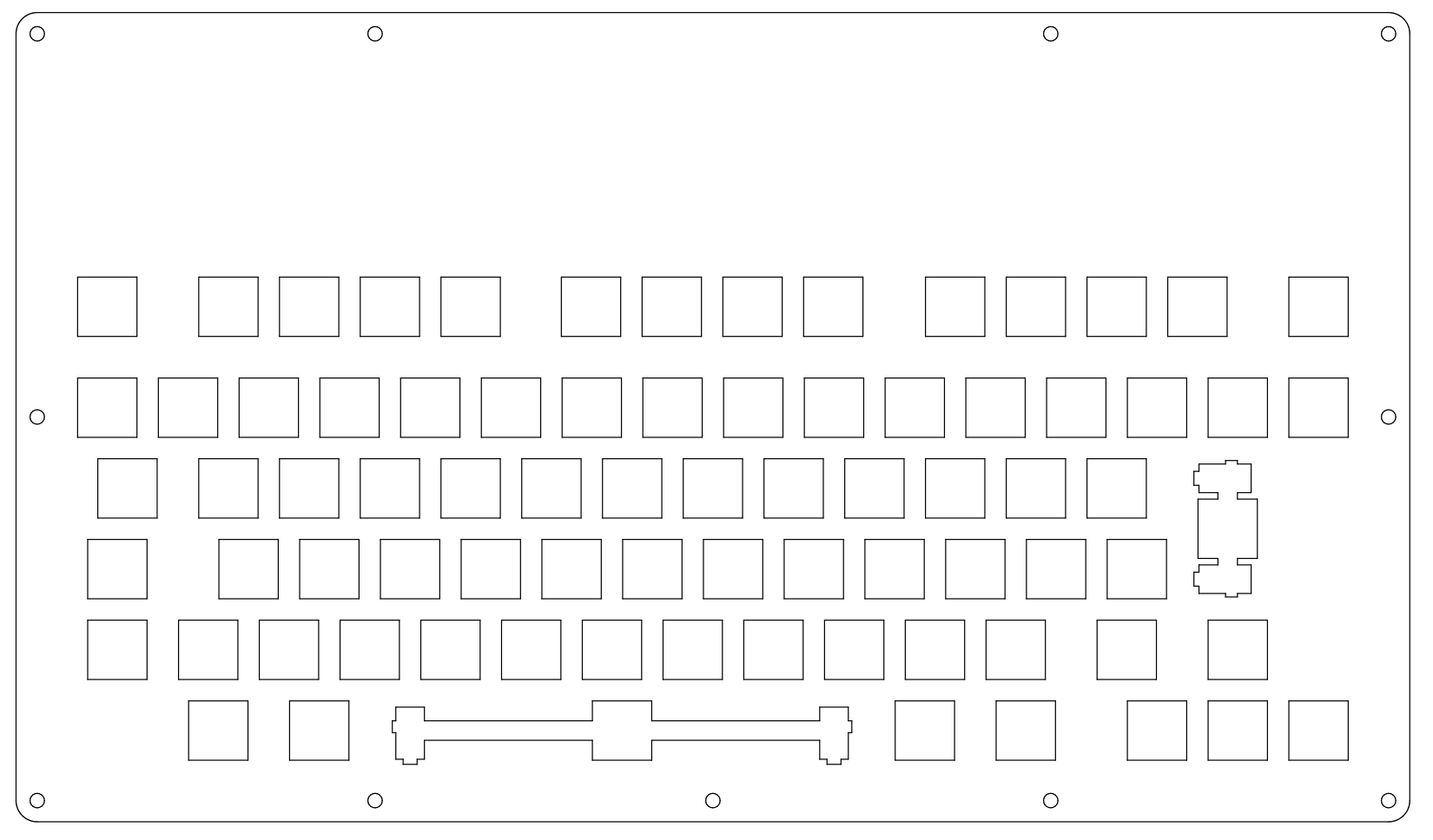
And here’s the switchplate layer. Note the rear center screw hole is missing, since the cutaway for the USB cable sits directly under there right now. I might wind up moving it:
I’m toying with the idea of making a mount point on the bottom layer to fit a Pi 4, but I don’t know if it’d make the case too thick, or how it would handle the heat. The Pi 4 I have here doesn’t seem to cope with heat well using just passive heatsinks, and is always throttling. I don’t want to have a fan in this thing. I’ll probably just leave the Pi out.
No timeframe on actually building this out yet. I’m still tinkering with the design almost constantly right now. And I’ll need to save; just getting the layers cut will probably come to about $150 - more if I go the ABS route instead of acrylic. Then there’s the cost of the PCB and stabs. I already have the caps if I stick with Susuwatari instead of trying to source all the needed /dev/tty kits, and a stockpile of Marshmallow switches I’ve been saving for the right project. This may be it.