I am wondering if i can have the Columns of my key matrix on the MCU (RP Pico) and have the rows of my matrix on a I2C expander (using a MCP23017). I have done some reading into it and haven’t found anything helpful except that the rows in col2row format are changed from high to low when the row is selected during scanning witch is done in 30uS by default in QMK. I am only wondering because i am one pin short of enough pins for perkey rgb with my matrix being 19x6 with SCL and SDA pins for the expander and oled display i am using.
Are you looking at a PCB that already exists with a 19x6 matrix? If you’re still designing it or you’re hand-wiring, 19x6 is far from optimized and with a few topographical hijinks you could squeeze 114 keys into fewer than 25 pins, possibly as low as 21 though going that low that would be unpleasant to map out.
1 Like
Making a 19x6 in to a 10x12 would probably be the easiest thing, other methods (charlieplexing, IO expander, round robin, etc) often require modifying or using different code for matrix scanning. As a simple example, this is the keyboard.h from one of my 4x12 orthos that has a 8x6 matrix.
#define LAYOUT(
k00, k01, k02, k03, k04, k05, k40, k41, k42, k43, k44, k45,
k10, k11, k12, k13, k14, k15, k50, k51, k52, k53, k54, k55,
k20, k21, k22, k23, k24, k25, k60, k61, k62, k63, k64, k65,
k30, k31, k32, k33, k34, k35, k70, k71, k72, k73, k74, k75
) {
{ k00, k01, k02, k03, k04, k05 },
{ k10, k11, k12, k13, k14, k15 },
{ k20, k21, k22, k23, k24, k25 },
{ k30, k31, k32, k33, k34, k35 },
{ k40, k41, k42, k43, k44, k45 },
{ k50, k51, k52, k53, k54, k55 },
{ k60, k61, k62, k63, k64, k65 },
{ k70, k71, k72, k73, k74, k75 }
}
2 Likes
i was hoping that i could make the schematic layout for the keys match the physical layout for the keys so the routing the traces would be easier. but sense it is a 108 key board i will probably end up just doing it as a 10*11 matrix then just deal with the routing being harder.
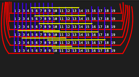
Bare in mind, my experience is with handwiring. So this might be a bit simplistic and I’m not sure how it would work with routing for rgb as well. But I’m thinking Rows (red) on one side, Columns (blue) on the other side of pcb. Only the left group of columns connected to mcu, and the right group of columns connected (yellow) to their corresponding first group columns on the same side as the row traces with vias.
1 Like
For my bigger hand-wires, I’ve folded the matrix, basically cutting the rows in half, then stringing two “banks” of 6 columns together. I think for something that would be 19x6 if wired “normal,” you’d end up with a fairly easy to trace 10x12. Not fully optimized, but you’d save a few pins without making it too much harder to follow manually.
3 Likes
Yes, this is indeed the best solution.
And also I am not sure that QMK support I2C expander on ARM MCUs.