Hi there!
Being new to mechanical boards i bought a Qisan Magicforce to lay a cheapish figurative groundfloor and get into some light tinkering and modding.
The shipped cable is a mess and it being mini-USB I am wondering how easy I can just swap out the mini-USB for a USB-C one to not invest into old tech cables and learn something in the process.
Since the mini-USB is on a seperate daughterboard there seems to be no need to change the surfice mounted device which afaik is nearly impossible anyway but I can just swap out the daughterboard for a USB-C one that I can purchase of aliexpress or amazon.
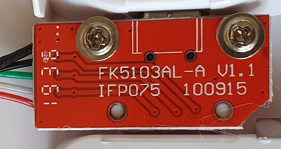
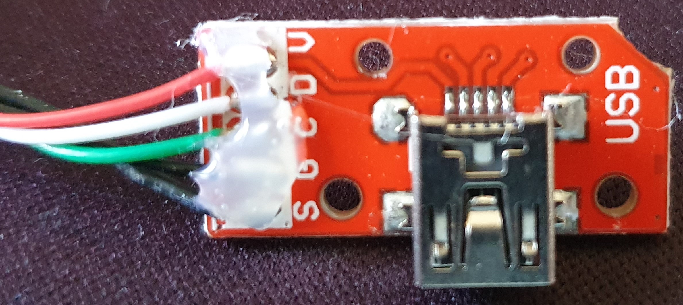
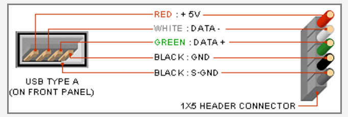
The Qisan is a bid of an oddball with its 5 pin connector cable (Magicforce 68 USB-cable compatibility problems). The connections are marked S (shield, connected to the connector frame), G (ground, connected to C, D and V), C, D, V and differ from what I see on USB type C Daughterboards (V,D-,D+,G or even A1 to A12).
How do I connect these cables and make it work with the new daughterboard? Should I also add a resistor to the board to mark the keyboard as sub-device for USB-C communications?
Here are two pics of the daughterboard in question:
Ah thanks! I thought they were just labeled differenty but wasn’t sure. This confirms it.
Is there something like a connector shield on USB-C? The cables I checked didn’t have it but the two mini-USB I had laying around both did. Or can I just connect the S and G wires like mentioned in the GH thread without negative impact?
I’m open to suggestions for usb daughterboards but I am having my eye on something like this 24 pin board or misuse a breakout board for easier un-/installation with screws (the Qisan molex connector is a pain to disconnect).
The Pololu one may be easier to work with, and it already integrates the 2 5.1K resistors.
The problem is, none have the USB shield connected to a specific pin hole on their board (they all look internally connected to ground) … and your keybaord pcb seems to request that.
Maybe read the GH thread more in detail to understand what could be done.
A perfect solution would be to manufacture a custom PCB replacement part with the USB C connector.
I would have personnally done that, but I understand that you don’t want to go this route
I got a Magicforce as my first place to experiment as well. I tried this very mod although with little success and little electronics experience I was also using this replacement PCB so YMMV: MF68 v1.1 PCB – SpaceCat Design
From what I understand you’ll want a USB-C receptacle hooked up with a resistor to help regulate how the computer recognizes the USB-C and also regulates power consumption. When I hooked up a raw USB-C receptacle it allowed things to power on, but it was unregulated power consumption I think because macOS complained about the device taking too much power.
I hope this helps. I think Adafruit has a USB-C breakout with the resistor on there to help ease with prototyping.
Ok, so after reading into PCB design I think this might be a little too deep for a start, I’d have to reverse-engineer the existing daugheterboard first and so far I don’t even understand how the S-Pad is actually connected to the connector-case since there is no connections shown.
Also in my newb head I am wondering what determines the energy consumption on the daughterboard since the only regulating chips are on the mainboard.
Thanks for your help - I guess it’s just a little too much effort on a cheapish case that has quite a large amount of caseping anyway to go through just to skip over buying a third party (old tech) mini-USB cable
Swapping the whole PCB is also out of the question for I am using an ISO-DE layout which limits the options and drives up the price.
Are you sure S is actually connected to anything on the daugtherboard? On the picture to my layman’s eye it looks like it’s just soldered on a pad that doesn’t go anywhere. Which potentially means it could be ignored…
For what it’s worth, I basically did what you planned with my Filco (replaced the hardwired USB-A cable with a USB-C connector for flexibility) but it does have a simpler setup with 4 wires only. I used a 24pin breakout board simliar to what you linked above.
Yes, they are connected, even though the connection is not shown on the daughterboard. I checked the connection from S on the molex connector on the motherboard all the way to the female mini USB connector casing with a multimeter.
Your layman’s thoughts were exactly my own, which only confused me further when I checked the connection.
And you have to be very carefull on those USB C daughtedboards found on the NET.
Some are with resistances and you can falsely assume they are 5.1K tied to ground (to be used in USB device mode) while in fact are connected elsewere to be used as a USB host mode (and your keyboard would not be recognized at all as a result).
Here is a very instructional video on the use of those USB C daughterboards for various scenarios:
I’m trying to understand the whole resistor and host/device meaning. I’m not an expert, I just try to understand it, because same as @shorle, I want to mod my keyboards to usb-c.
The video says that host/device is determined from resistor on A5 and B5 pins. However these pins are not connected to the cable, so this host/device information is only propagated through the connectors to the device (pc or keyboard), but not via cable if I understand it correctly.
Also the resistor is only on the male connector, not on the female, right? Or are resistors needed on booth? One breakout board @shorle linked has resistors, other one does not.
But anyway, does it matter if there are resistors on the keyboard female usb connector or not? This information does not get propagated to pc and for the keyboard it doesn’t matter I assume.
Few weeks ago I made this usb-c female to usb-micro male adapter because I didn’t have usb-micro cable at hand atm. The usb-c female does not have any resistor. I can plug it to usb-micro keyboard and it does work with my PC. However I’m not sure if this is the right way to do it, if it would work on other PCs.
Photos: https://imgur.com/a/0MeSDJ2 (can’t insert photos as a new member)
This is only the case if you use a USB C to A cable. In such a case it will still work without the resistors. If you use a C to C cable it is most certainly connected, and if properly implemented on the host (safe to assume for most any computer) the keyboard will not be able to be identified and will not work. I’ve actually had one or two poorly designed keyboards that did not work with my MacBook, probably because they were missing those resistors.
Tbh I’m not sure I follow the question, a regular cable will have CC1 on one end connected to CC1 on the other end, and no connection on the CC2 pins; this is how the cable orientation is determined.
There are a few special cases where you might have a pull down on the CC pins in the cable:
if it is an active cable the CC1 pins will be connected normally, and the CC2 will have some pull down to identify as an active cable so that Vcon can be supplied on that pin
if it is a USB C to A adapter where the C port is the host the CC pins would need to be pulled down to identify that the port is acting as a host.
To complement that, the USB specification is a huge document of several hundred of pages.
And the USB C specification (that is talking only about the physical connector and cables) is very complex all by itself.
For example it is quite common to put 5.1k resistors between CC1/2 and ground but can also use different values to specify the maximum amount of current that can flow through the VBUS line: 5.1k specify a maximum of 500mA, very standard value, but you could specify higher current values if you wanded to.
Thanks for the explanations. So the whole usb-c is more complicated than I have thought, but I have definitely learned something now. Will be watching this thread how will the connector change turn out.
Thanks for the link, it’s a helpfull guide to changing the host-side termination of devices.
Sorry to inform you but I abandoned the project and returned the Qisan MF69 - it was too much case ping to go through this hassle. Even with @patcoll 's linked breakout board the shipping to EU wasn’t worth it to me. It wasn’t a complete waste though since I learned quite a bit about USB and now I know that breakout boards aren’t as simple as I thought - I didn’t even know those 2 SMD chips on the one board I linked were resistors.
Also I got fond of the MF69s layout and am waiting on an Ikki68 Aurora now
While my initial question is no longer of concern to me there is still the issue of preparing female USB Ports on the device side to send UFP information on a mirrorable USB-C to USB-C cable but that’s probably easier answered in a new thread.