Does anyone remember if this keyboard came with a USB dongle of some sort, allowing it to connect via Wifi to a PC?
I know it connects via bluetooth and 5G, but I haven’t actually tried it yet, and wondering what you are supposed to do on a conventional wireless network.
So it does have two methods to connect, but wifi isn’t one of them - it will neither be helped nor hindered by the presence or absence of a wifi network.
Besides bluetooth, it has a dedicated radio dongle (2.4ghz I think) - this is what I use with it because it’s reliable and easy. The dongle is located in the battery compartment.
Being that this is ostensibly a GK68 PCB, is it remappable using Epomaker’s GK68 software? If I remember correctly a lot of that program’s functionality relied on a wired USB connection, but I’m wondering if any of it will work.
My kingdom for a cheap board like this I can program to be Mac friendly. Throw a few eneloops in and it’s perfect for the office.
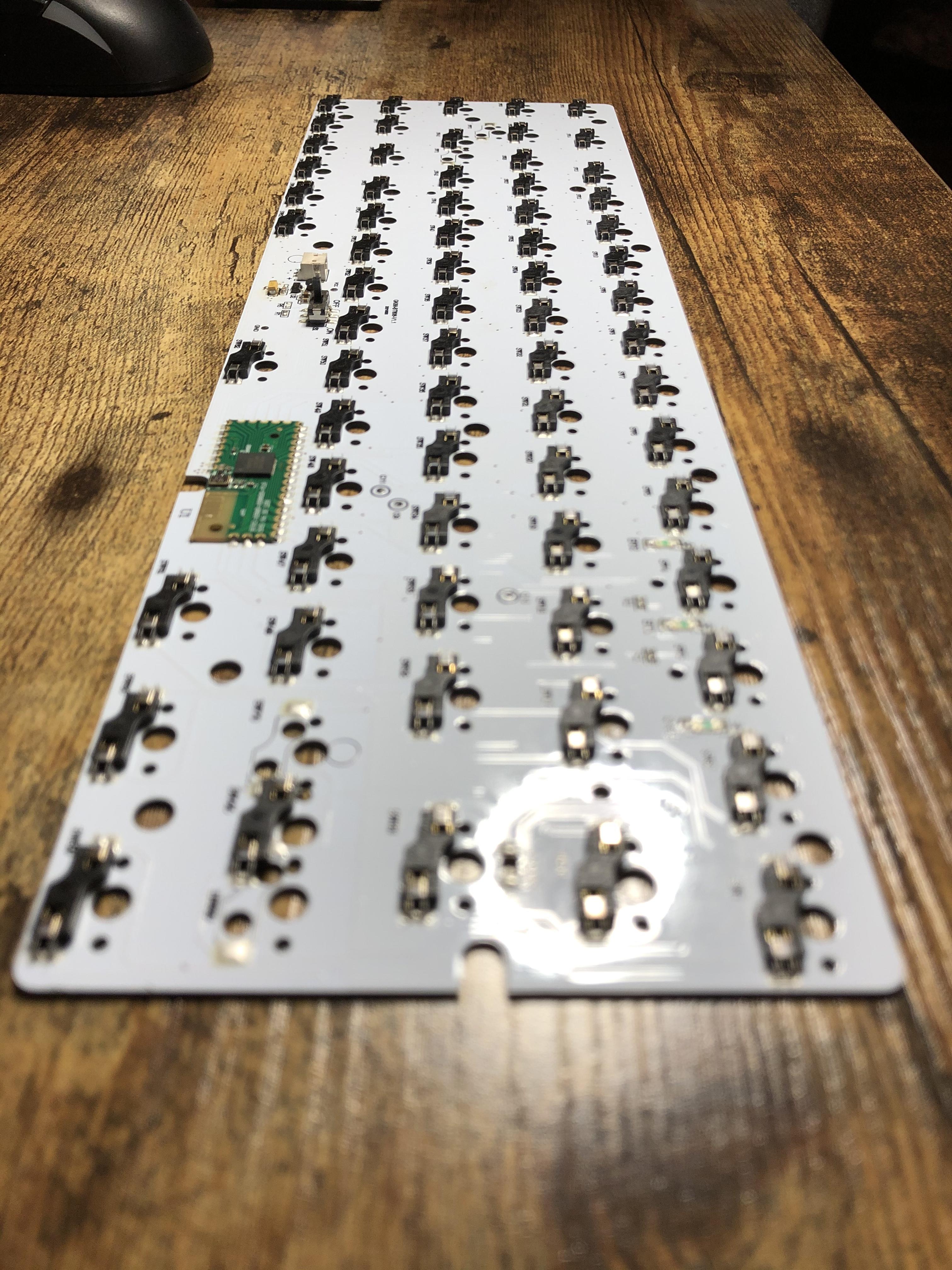
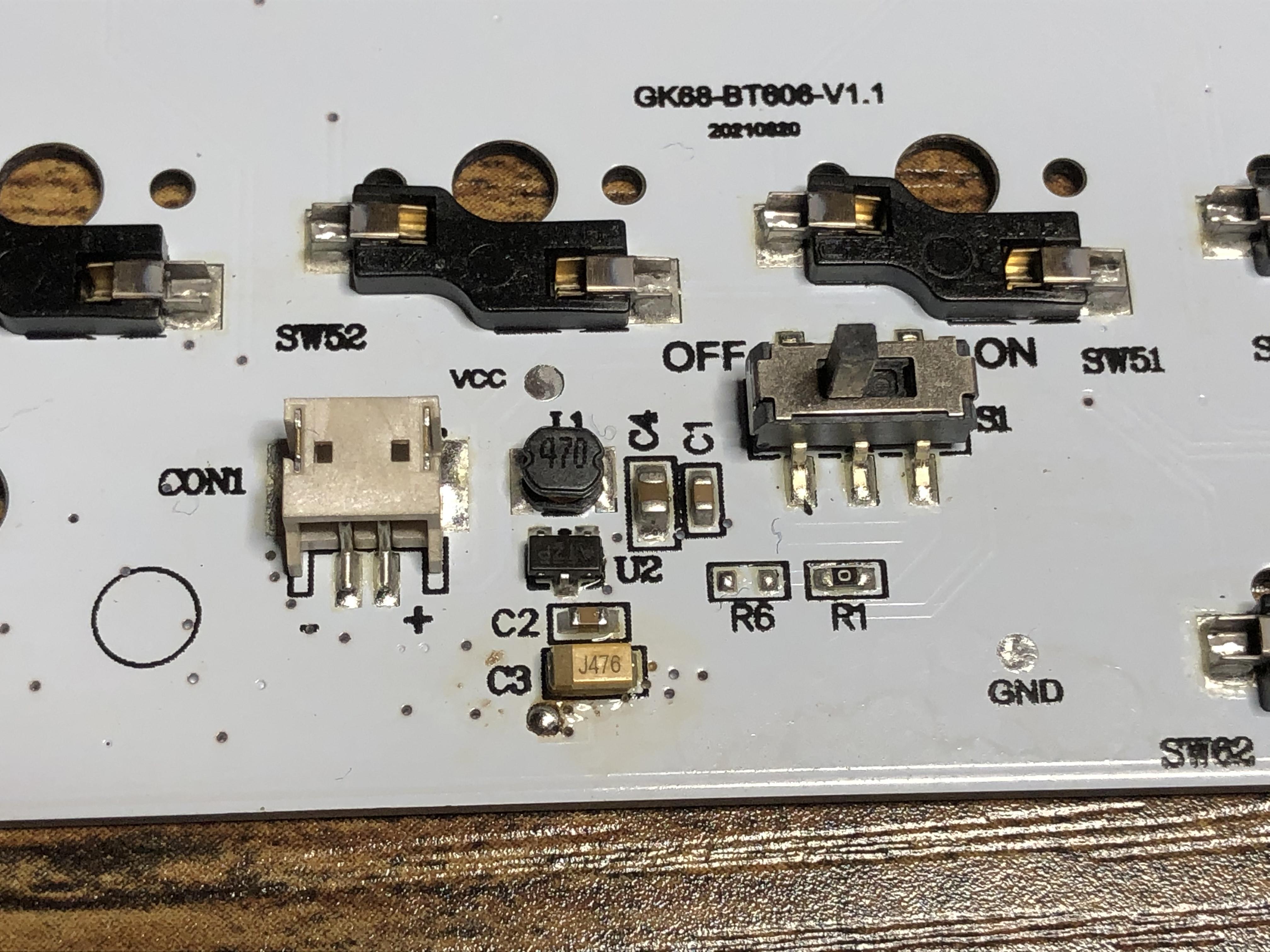
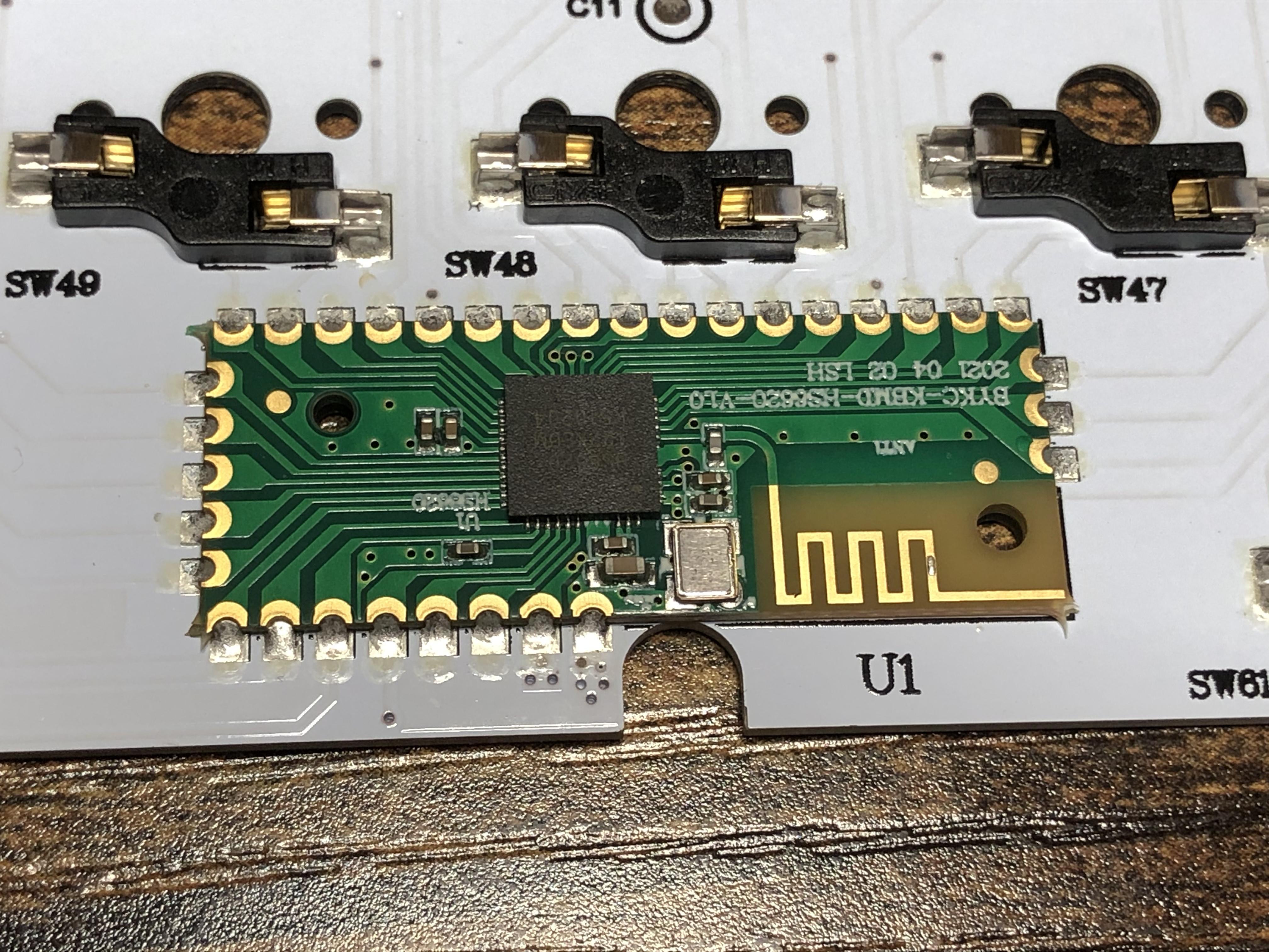
I took some photos of the PCB and the little controller board on it - which is pretty much the only thing on there besides the sockets, an on-off switch, and a few other individual components.
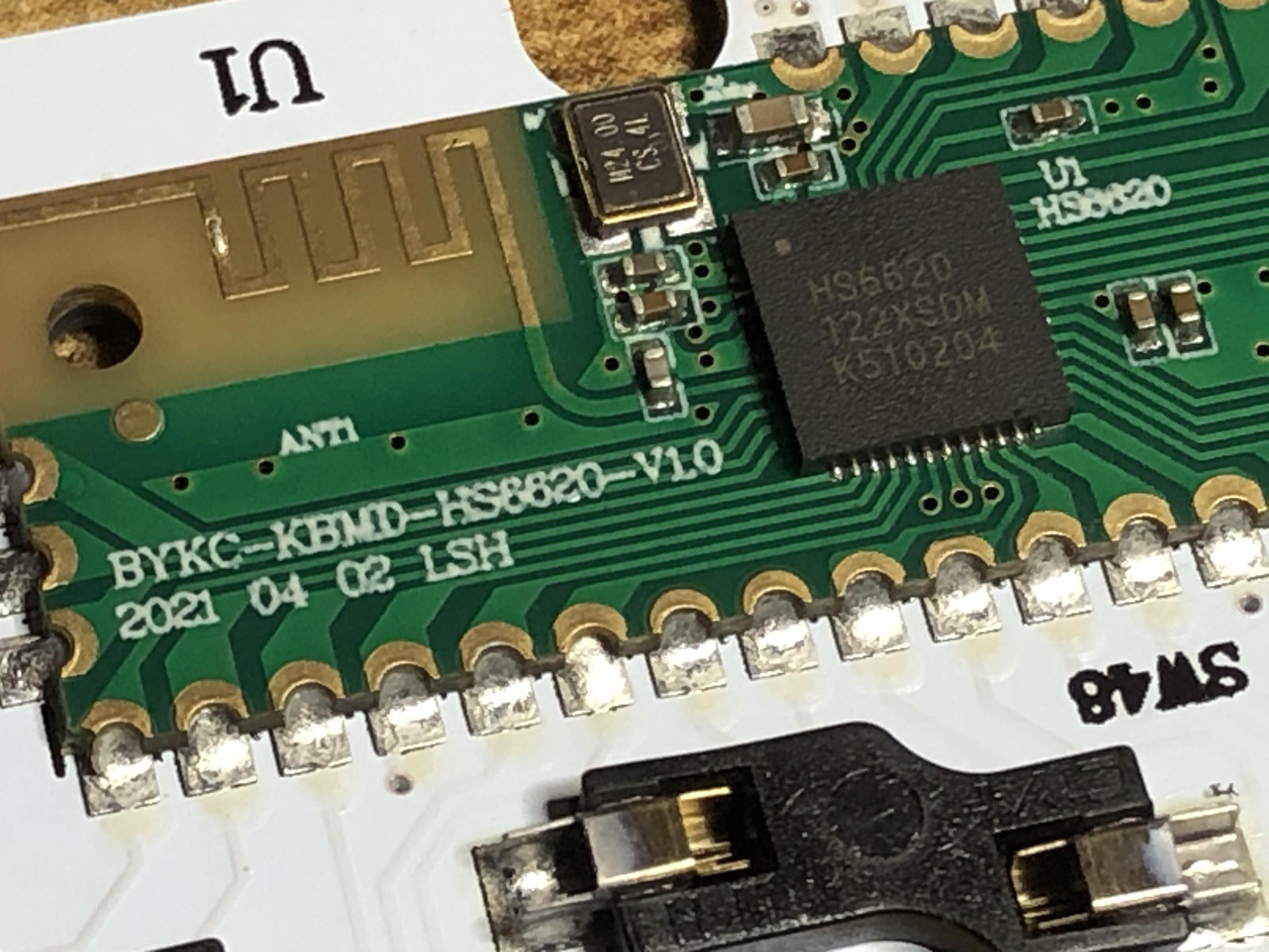
Here’s the controller - which also seems to be just about everything else. I’m guessing that squared-squiggle shape is an on-board antenna.
On the board is screened “BYKC-KBMD-HS6620-V1.0” with the date code “2021 04 02 LSH” - I think it actually says “ANT1” under the antenna thing - on the other side it says “U1 | HS6620”
On the main chip is written again, “HS6620”, and also “122XSDM | K510204”
The wee metal bit (crystal maybe?) says “M24.00 | CS 4L”
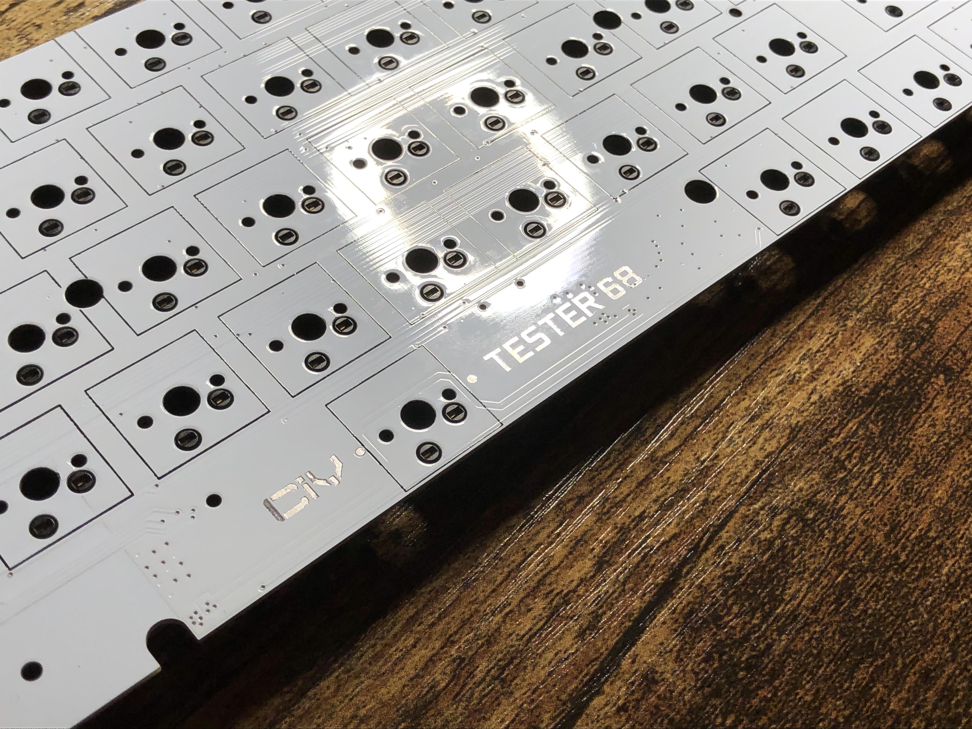
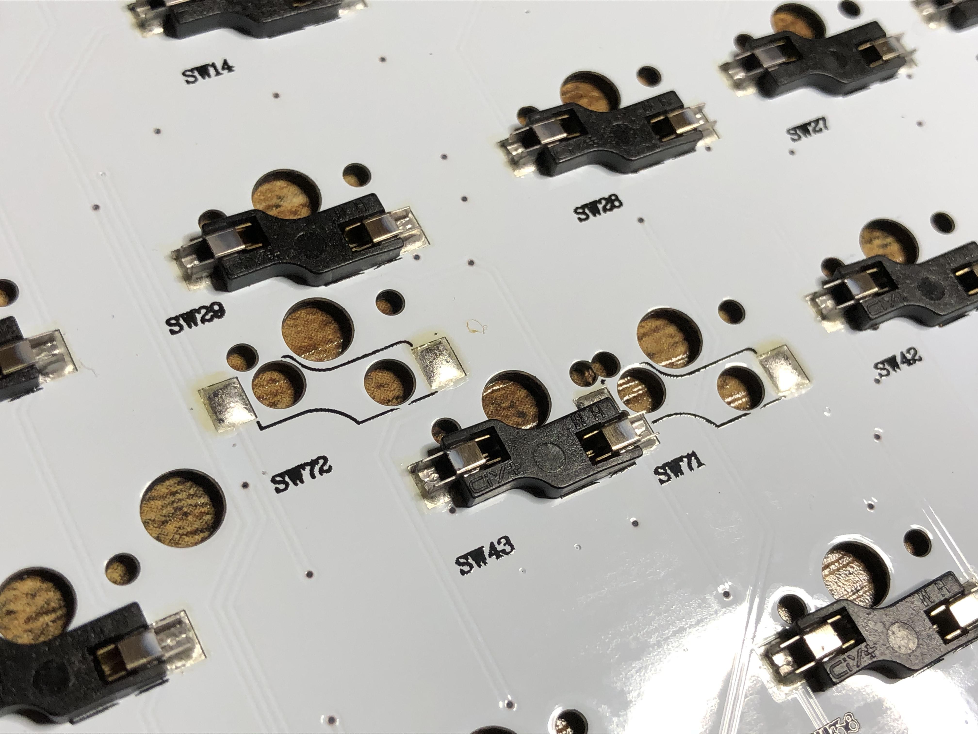
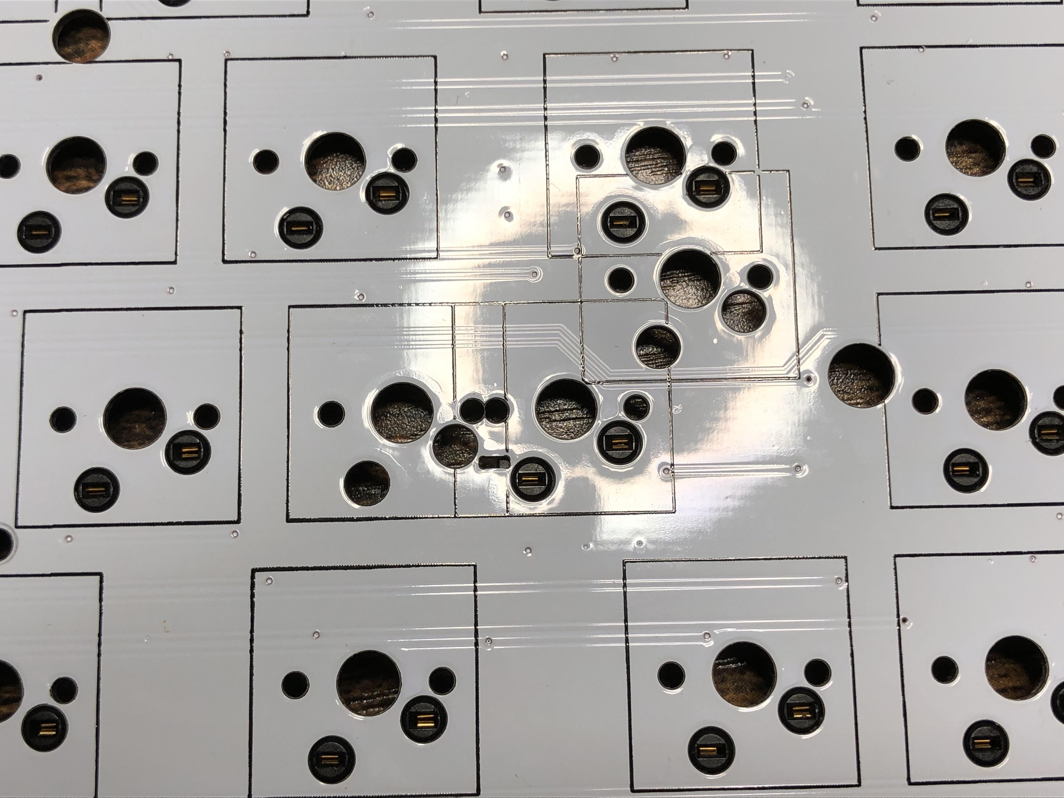
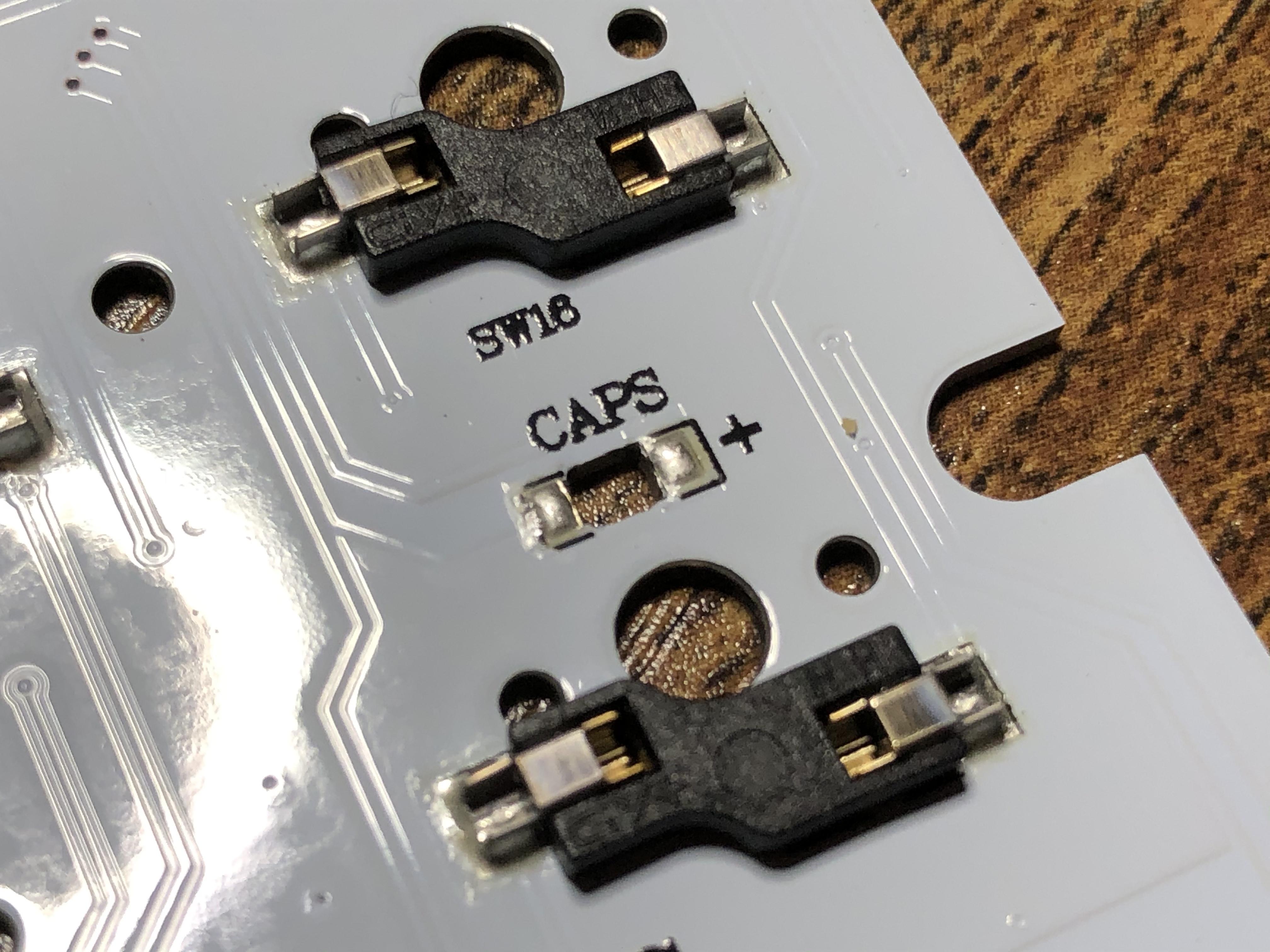
The sockets are also branded CIY+ (they also have either HM or WH on the other side), and it looks like there are alternate positions for some to accommodate other layouts.
Thanks for the detailed info, it’s interesting to see how simple that PCB really is.
If you ever have the chance to see if Epomaker’s software works, please let us know. Nuphy says they don’t currently have software, but that doesn’t mean software that works on the OEM PCB is out of the question.
appears to be made by OnMicro (formerly HunterSun). Lot of the results that came up in my search were for smartwatches that also use a version of this chip.
OK, so I finally assembled my Tester68 into something other than a simple testing keyboard.
Stabilizers are lubed, switches are Mode Signal [Durock Medium Tactile] 63.5 G lubed with 3203 and filmed with TX films.
The experience is beyond that of a $25 keyboard. The MG Monster keycaps complement the white case nicely, and make the Mode Signal sounds much thockier. The sound is fairly consistent across the metal plate. Switches are extremely smooth, but more tactile than Browns.
I’m connected to my PC via the wireless 2.5 network or whatever. If this can do the same to an NVIDIA Shield TV, it would be game-changing. Just gave it an arcade game test, and it passed perfectly. Only thing I dislike is the no-blocker 65% layout, which is why I would prefer to use it as a media controller, rather than a regular keyboard.
Maybe I’ll post a photo tomorrow if it’s sunny out.
Hi, all! Thanks in advance for all the detail info about this interesting cheap tester. I’m very interested on getting one and try to make it ISO, since it has the holes for it, I guess it would be a matter of desoldering the sockets. However, it also uses plate-mounted stabs and I’m not that sure how could I make it work with a different layout. I’m thinking of creating a template on CAD and making a plate myself, but I would have to figure out the position of the holes to screw it to the base. Anyways, if someone can give me some info or feedback about making it, I would really appreciate it!
I think having a plate made / making one would be the way to go if you wanted to reconfigure this board. I’m sure there are folks with more knowledge on this than myself, but I’d start with a scan of the stock plate, create a vector file based on it, and then modify that file to accommodate the ISO layout - possibly using a scan of the PCB to help with positioning. I’m not sure how much work would be involved there but at very least it does seem like it would be possible.
I was thinking of using the builder tool from swillkb (can’t post a link here) to help me get the layout done and then somehow figure out the positioning of the mounting holes, but I really really like your idea. I could combine both to make it more accurate. Thank you for the tip! Also, btw, I haven’t desoldered a lot of stuff, do you think it would be hard? I have only desoldered a couple of switches…
As for de-soldering sockets, that’s something I haven’t tried yet. I’d imagine it’s not as easy as switches since they aren’t through-hole, but shouldn’t be too hard wit a little patience. They have two contacts on either side that solder to flat pads.
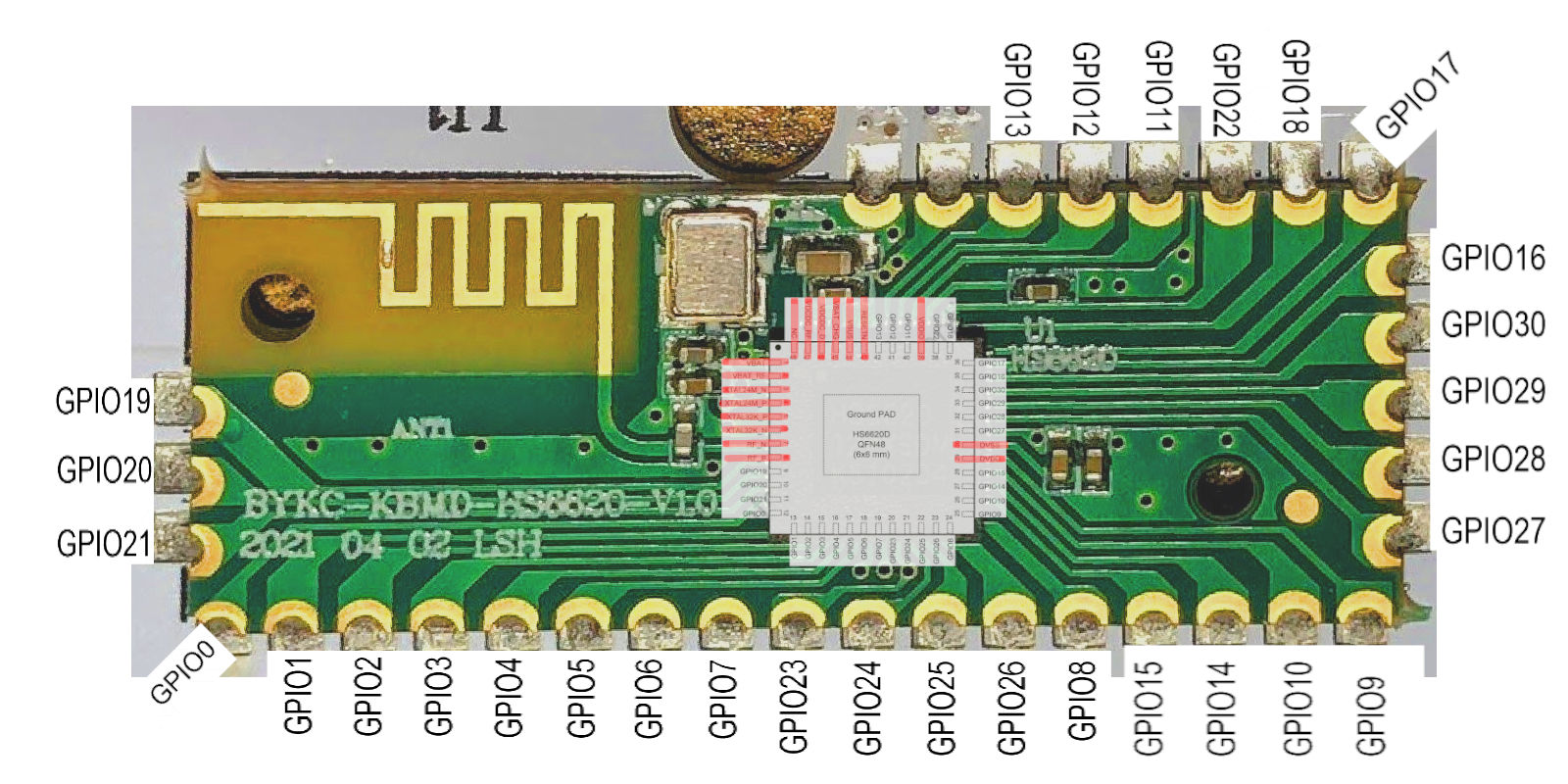
So I bought this board recently as well, and was wondering about adding my own microcontroller to this board so that I can have more customization and better more stable connection. I found this post, and info in here helped me a lot so far. Mainly kidpixo’s image with the GPIO pins.
I don’t believe this has rows/columns layout, or at least I can’t figure it out. I have mapped what switch pins lead to what GPIO pins tho, figured I would share it here. It’s in this google spreadsheet.
Hello Deadeye, I can see that you are very much into the keyboard community. I purchased this kit too and it has been my daily driver since. I did a clay mod as a case dampener and I used it for the whole day so I thought I was good to go. The morning after, when I went to boot up my pc, my keyboard didn’t turn on. I got it checked and they said that my bluetooth receiver has a short. Can you give me any advice on how to fix this? I posted on reddit and no one was answering any of my queries. Please help. I love this keeb so much.