Did anybody try to add a custom led array to a regular ErgoDox EZ? It seems that regular ErgoDox EZ PCBs are the same as ErgoDox EZ shine, so one can solder a 4pin JST wire connector onto the halves and connect a custom LED PCB to get a compatible - or identical effect.
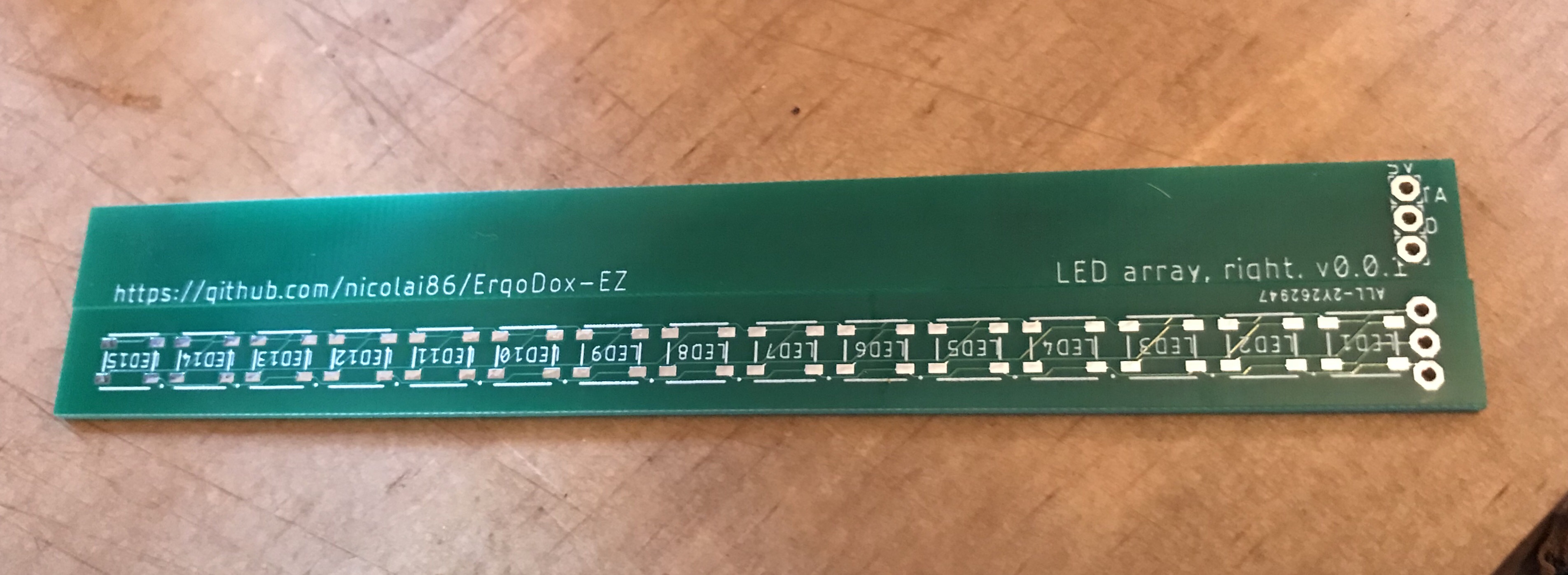
So I ordered my first PCB for the right side, as it seemed way easier to get started.
PCB will arive mid September and the LEDs early October - will update this thread once I’ve soldered & tested the first one.
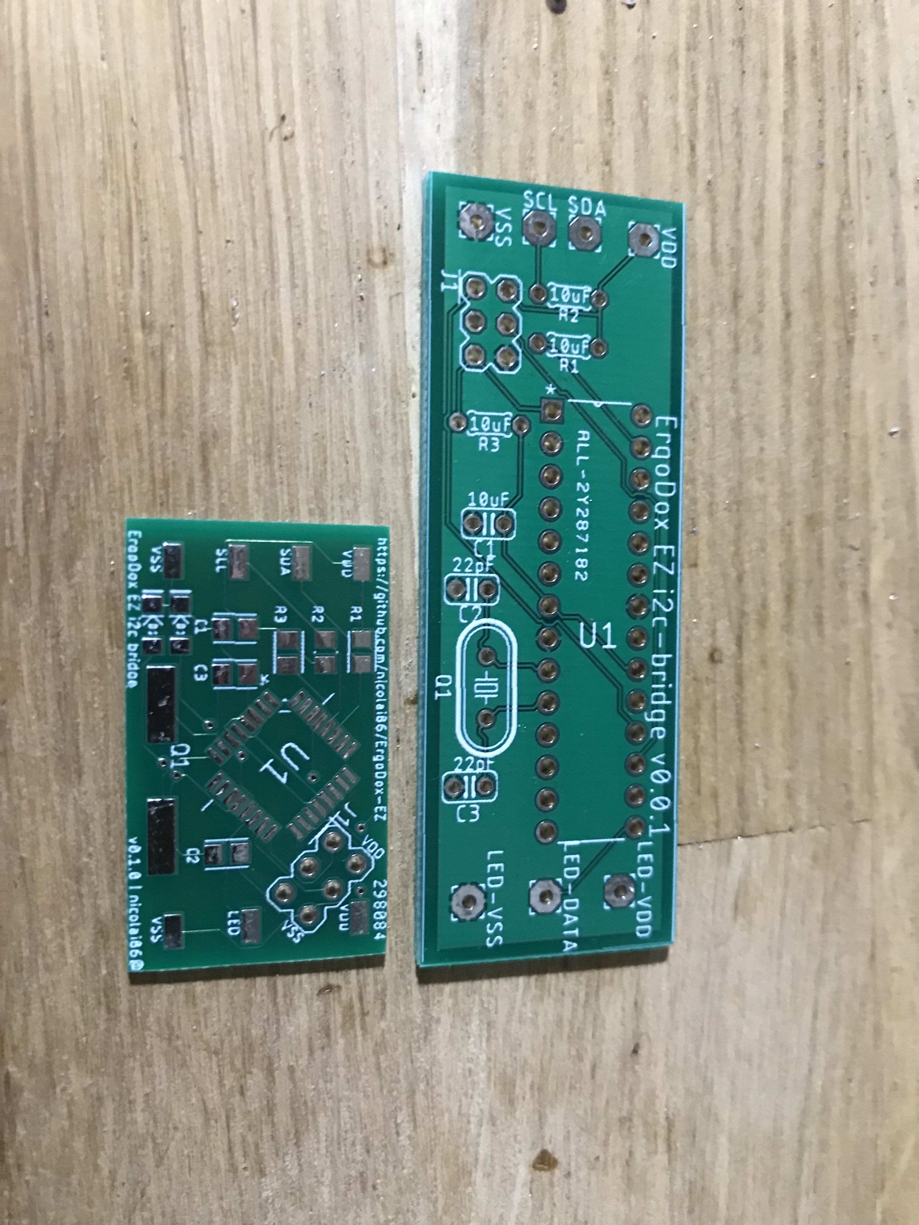
I’ve got the left PCB nearly done in Eagle, need to replace some of the libraries for matching SMD components, and create a custom one for one of the chips. This is on hold until the right side works.
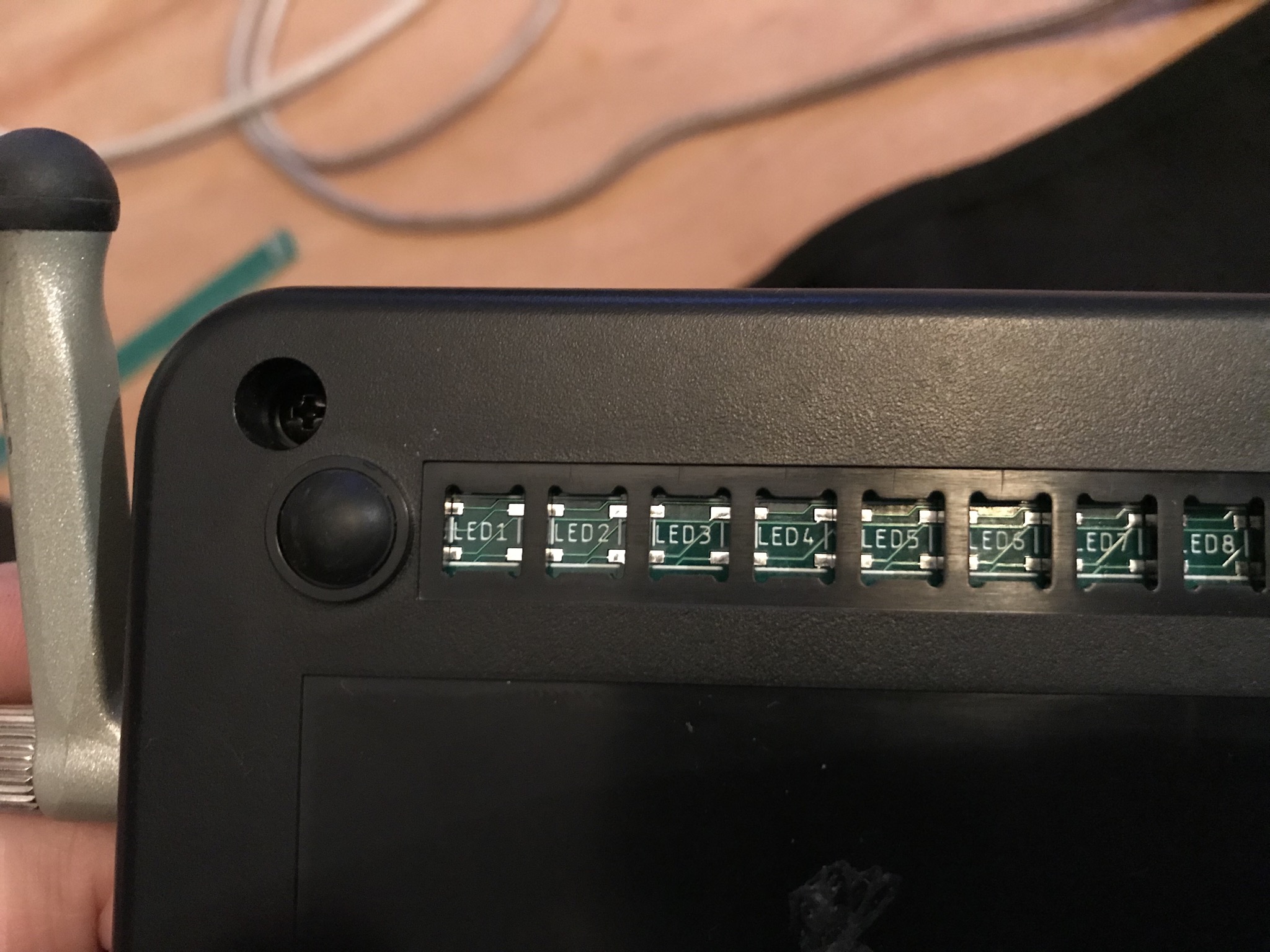
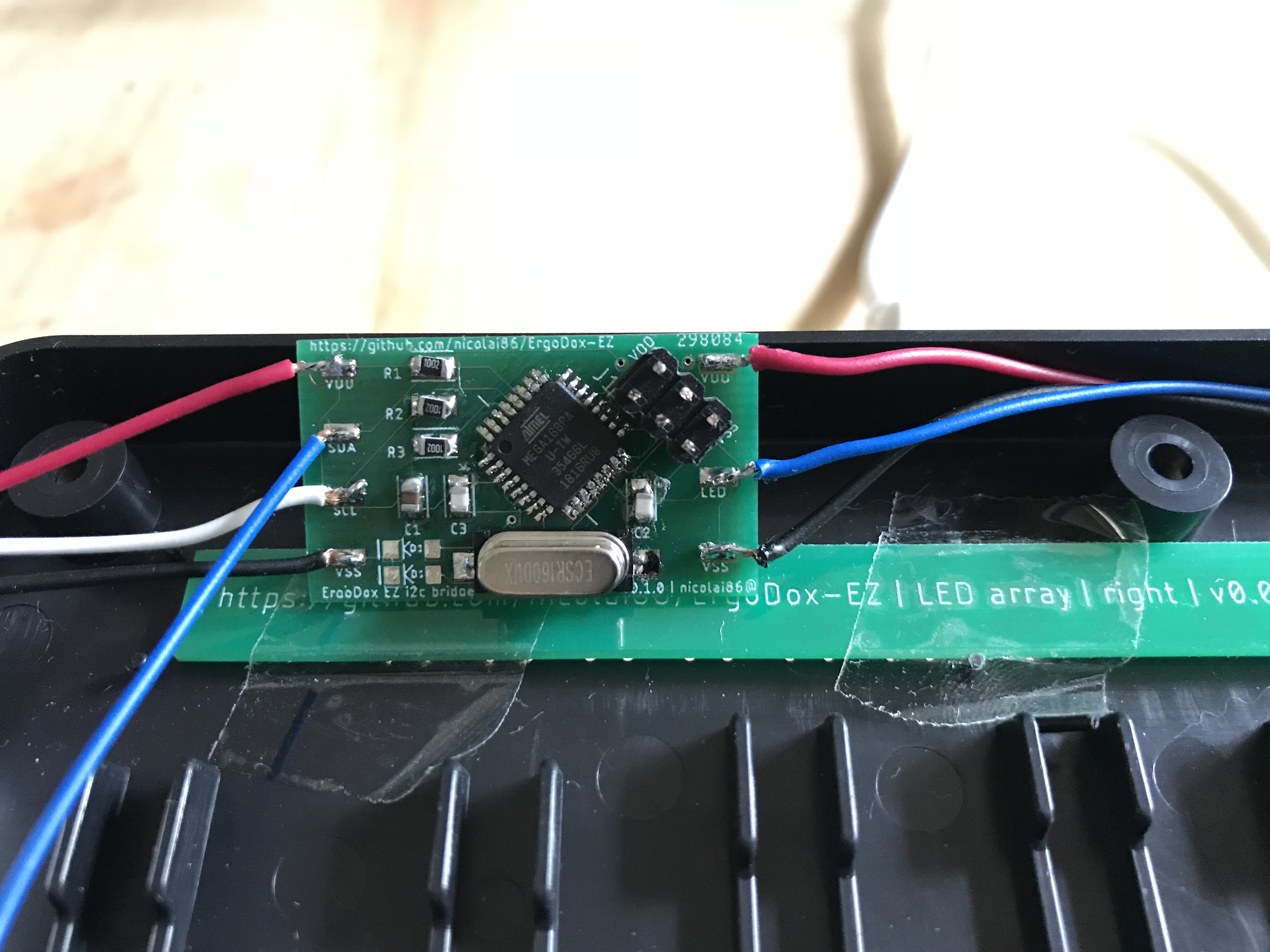
the fit is good; the small soldering bubbles prevent the LEDs from fitting 100% into the cut-out area, but that shouldn’t be an issue. Now I’m waiting for the micro JST 2.0 3-pin connectors to attach it to the keyboard circuits…
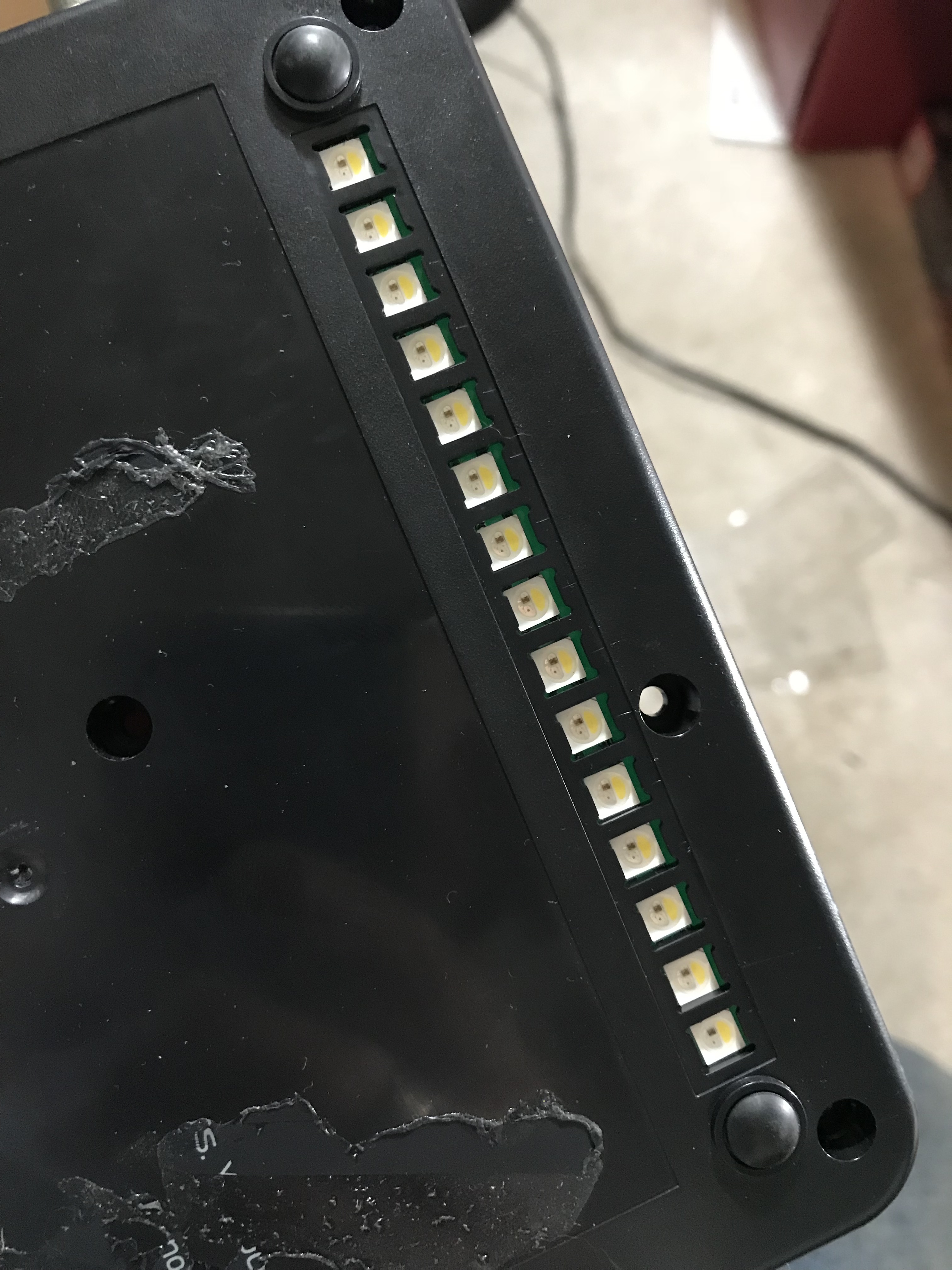
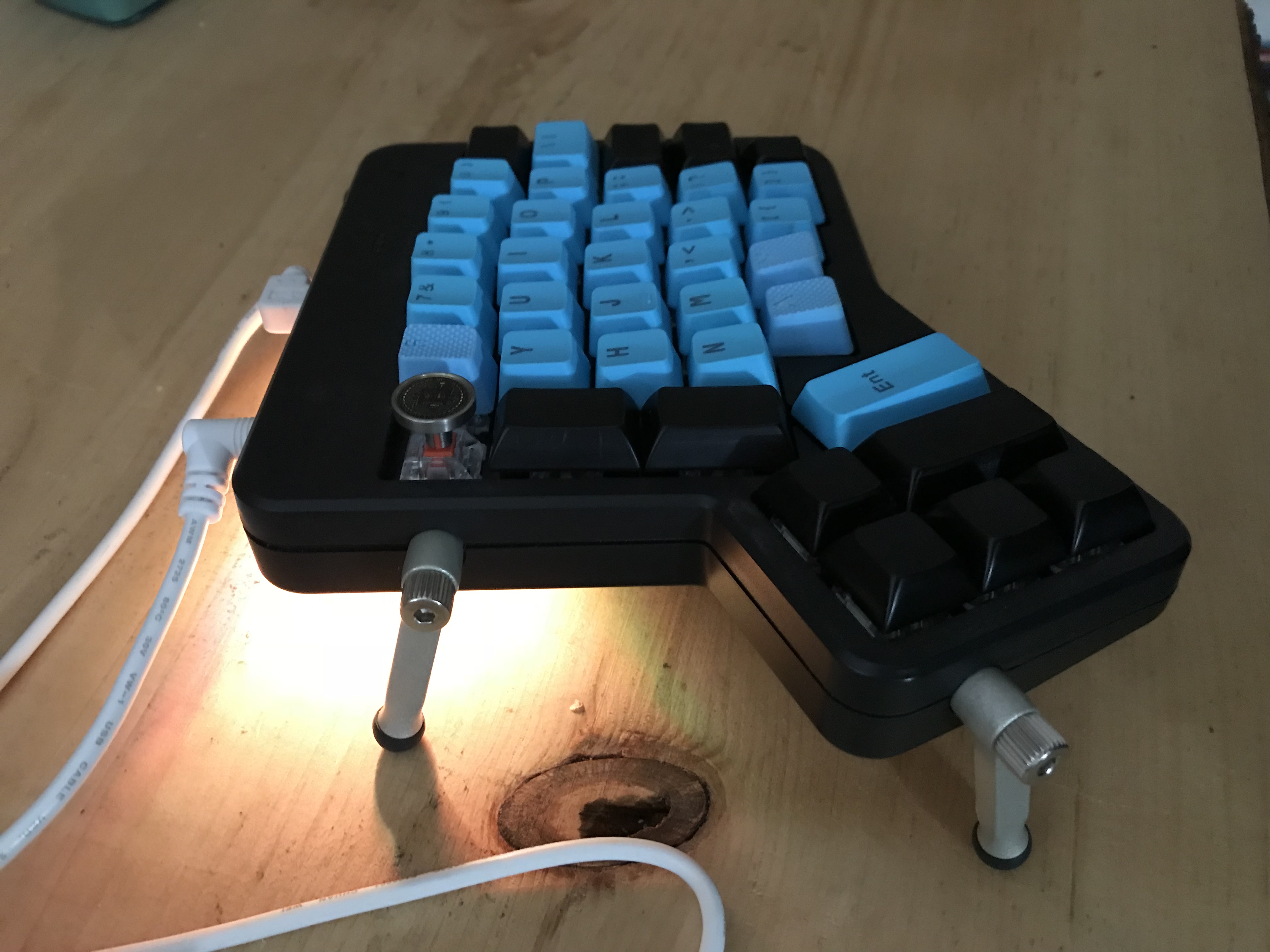
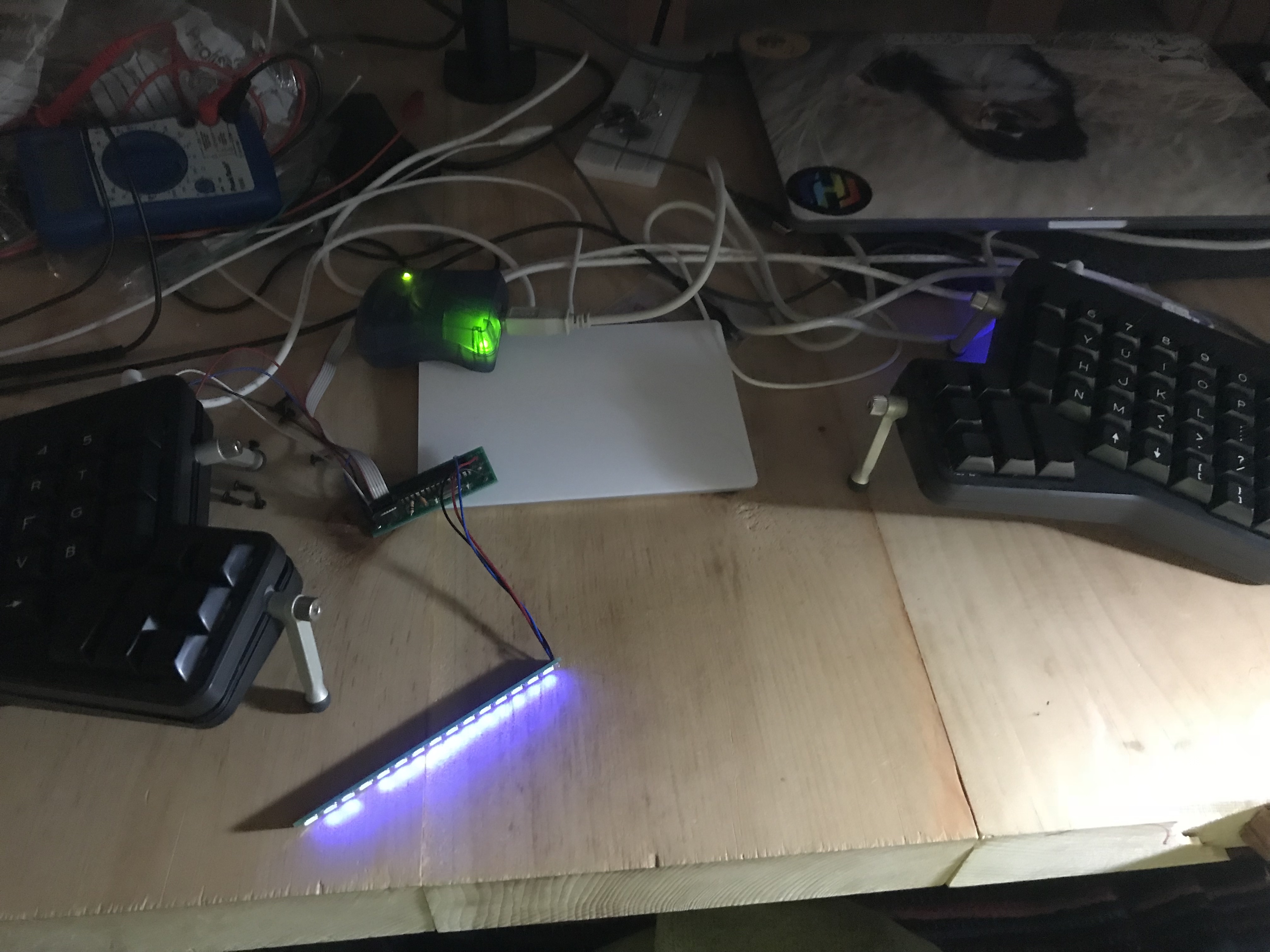
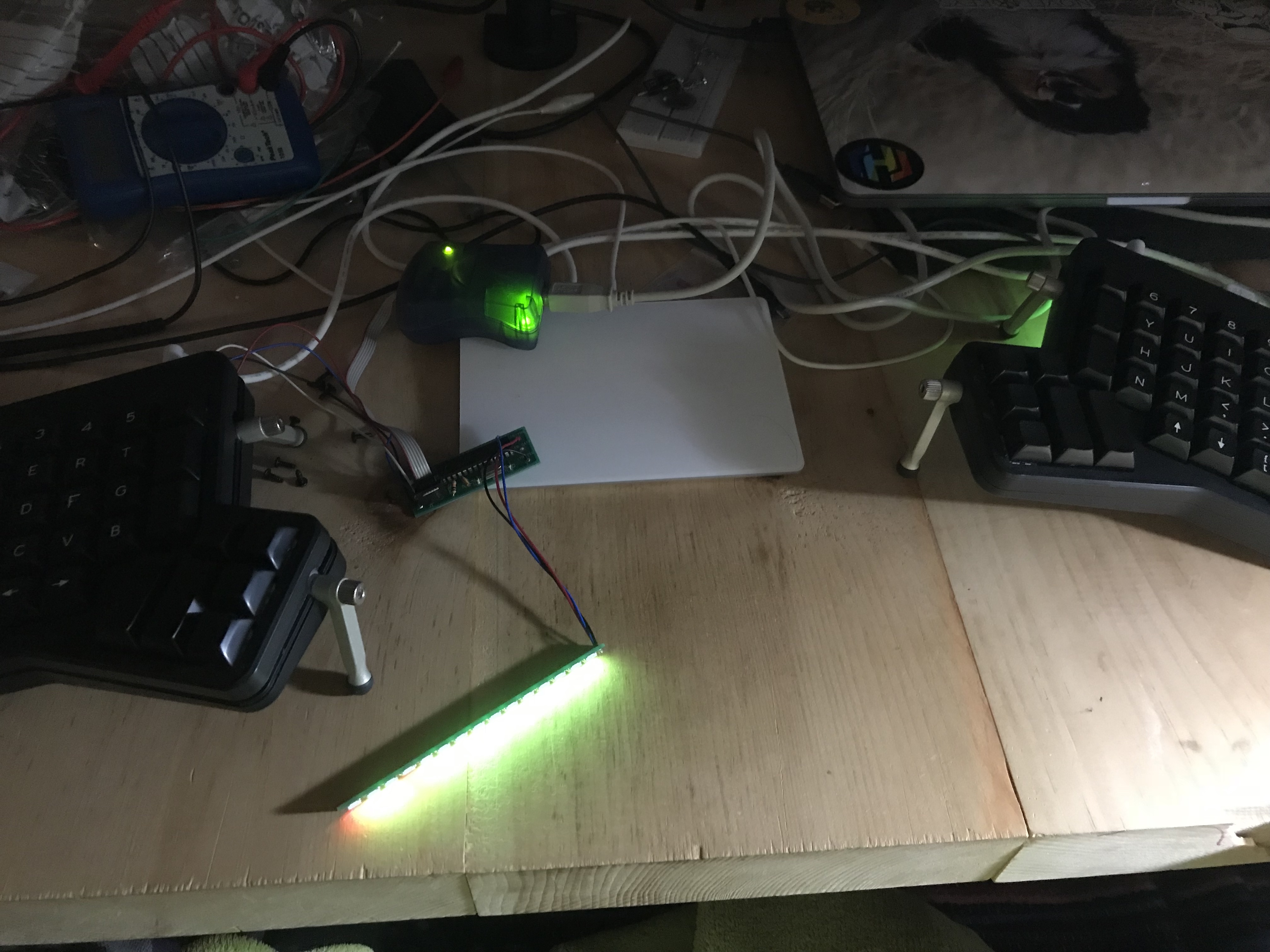
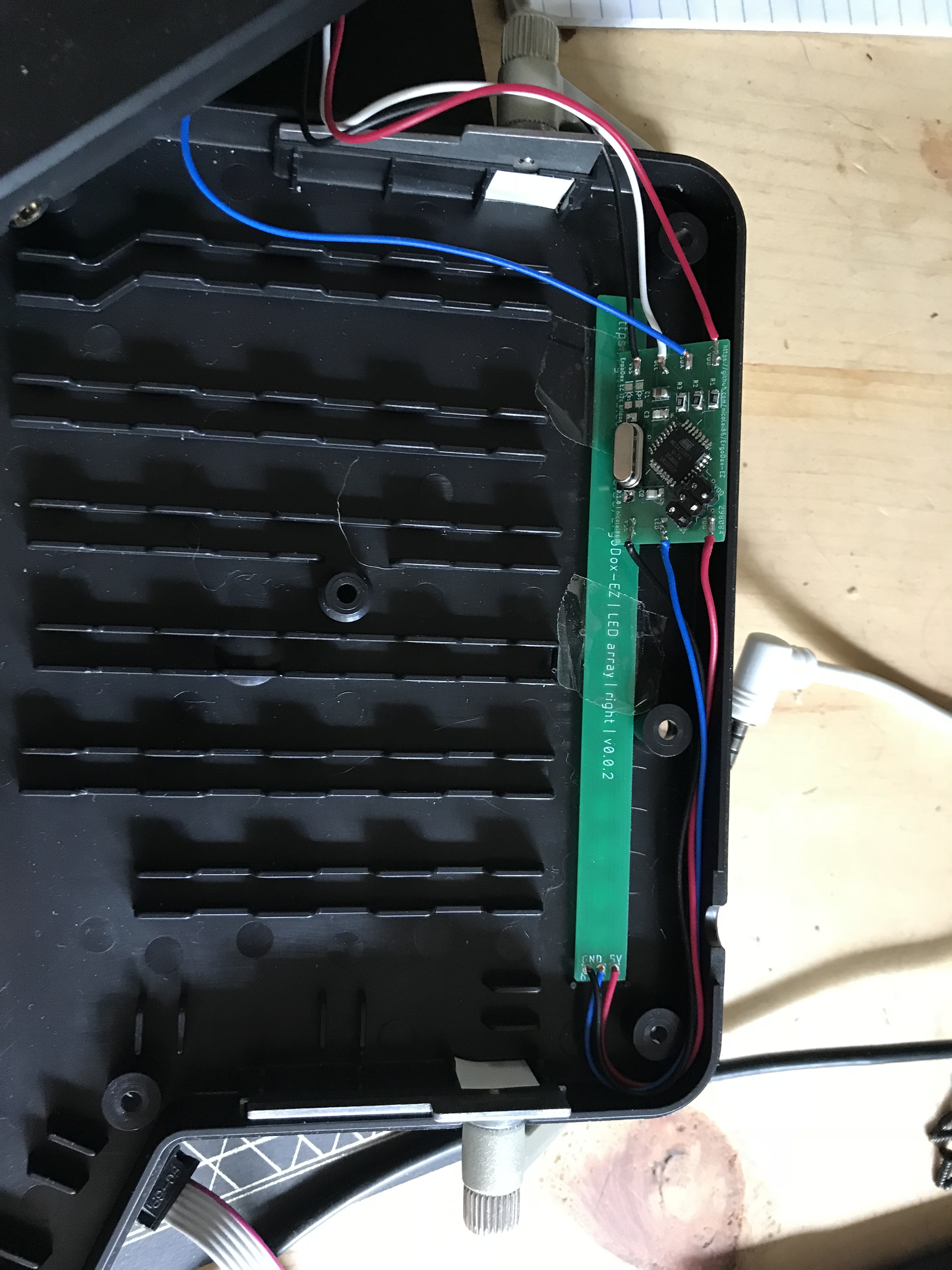
Using the voltometer I checked the right polarity, and voila: the right half works perfectly; even if the left half has no LED strip attached dimming and animations work fine:
I’ll omit the video showing the animation and color changing; it’s too huge for an upload.
Next up, left side.
Expenses so far:
learning expenses:
1x 10 USD for the 1st PCB prototype (5 pc) - unfortunately I was 0.2mm off on both measurements, so it did not fit
1x 1.95 CAD for wrong JST headers
actual expenses
1x 10 USD for the 2nd PCB prototype (5 pc) - which fits and attaches fine.
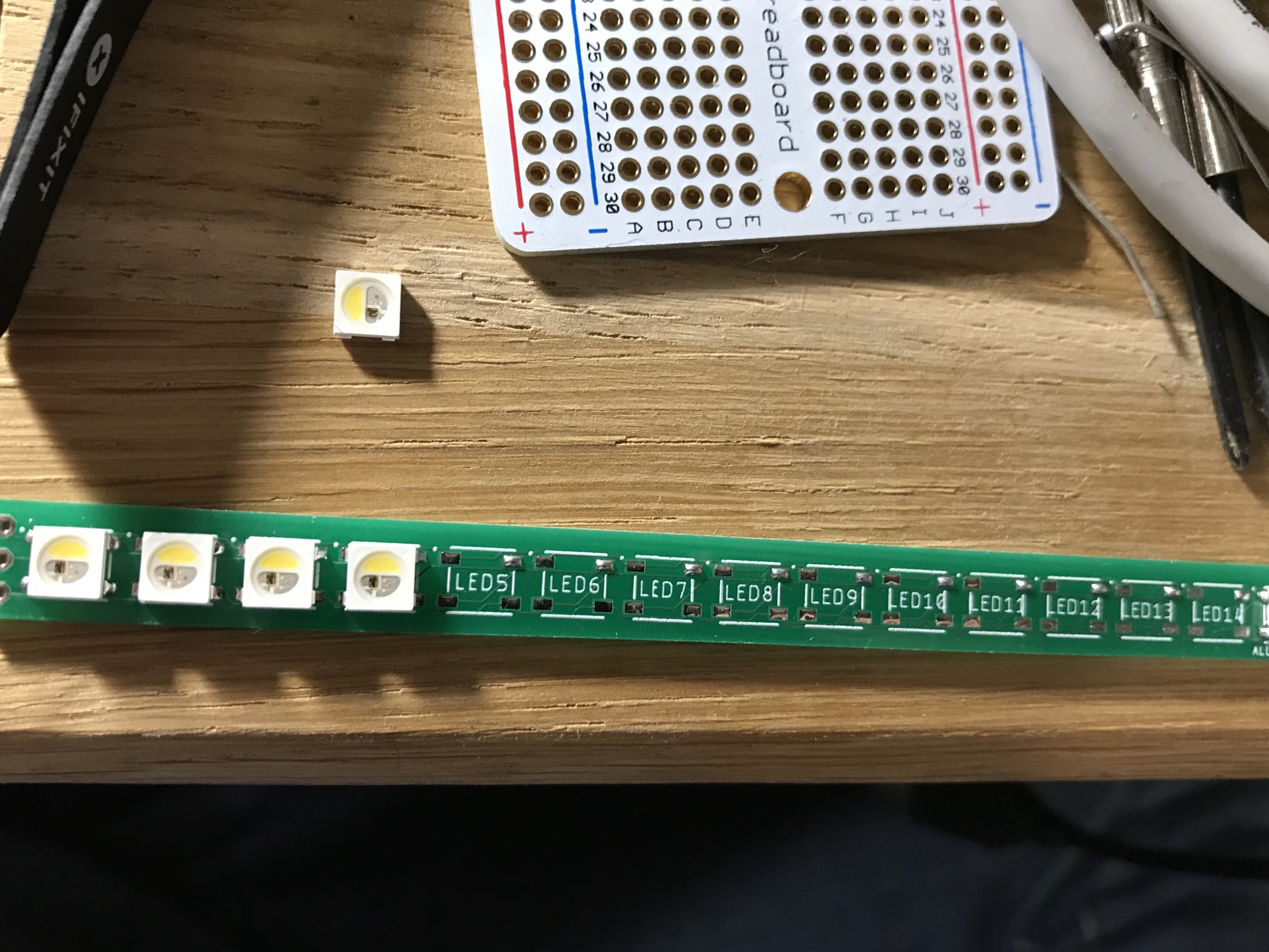
1x 10 CAD for 50 RGBW SK6812 LEDs from aliexpress.
so, not too expensive; also I learned a little why the PCB in the ErgoDox EZ is what it is which was great fun:
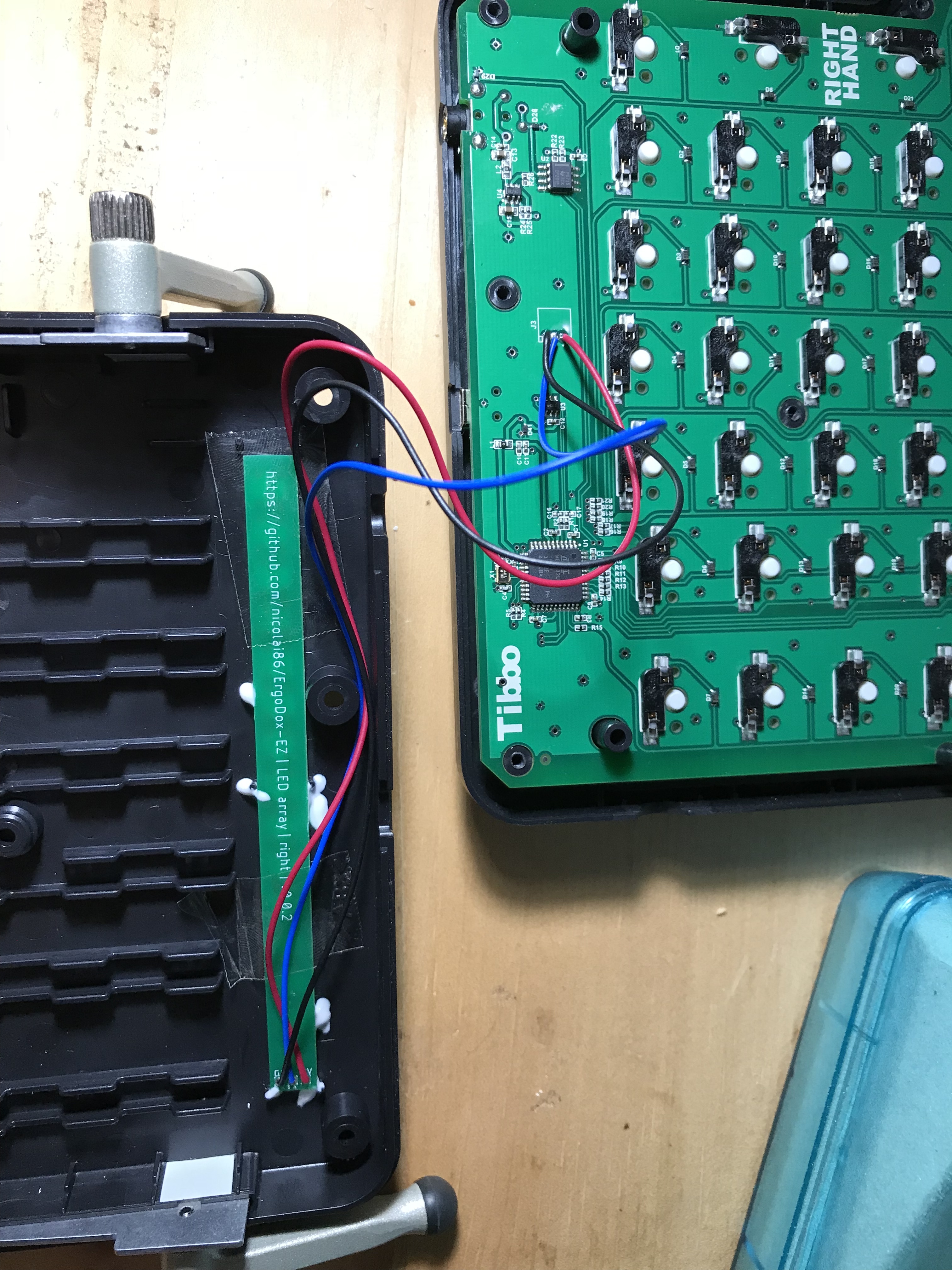
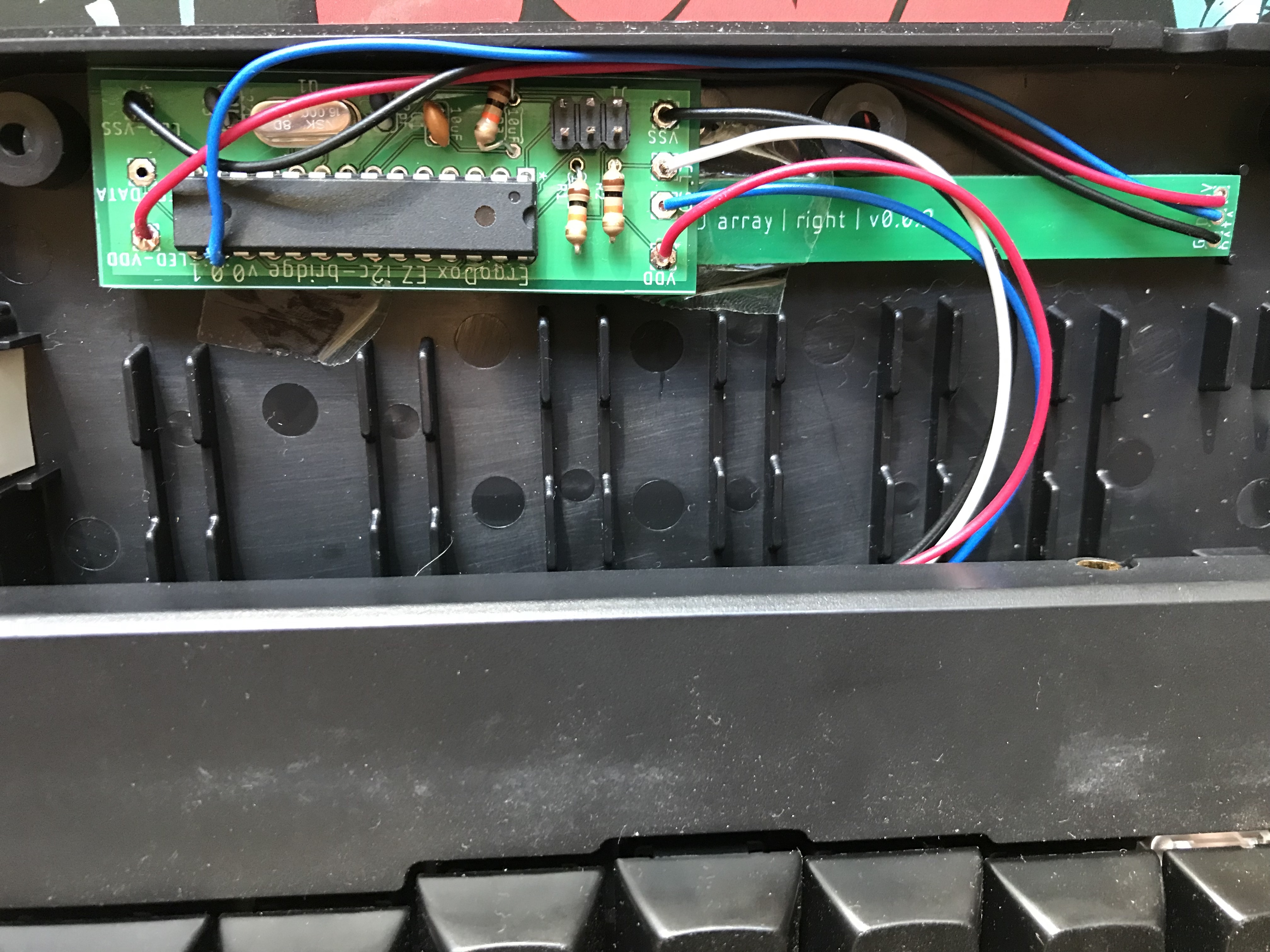
the ErgoDox EZ strip has 3 pads (vcc, data, gnd) on the left and 3 pads on the right side - turns out this is super useful! If you solder the LEDs rotated by 180 deg. - which I did at first - you can rescue the PCB by using the other side, as all pins still match. I had to throw away the entire row as I was unable to get the LEDs off cleanly. So that’s going to go into rev 0.1 I guess
Once I’ll have the left side working too I’ll open source the gerber files on github
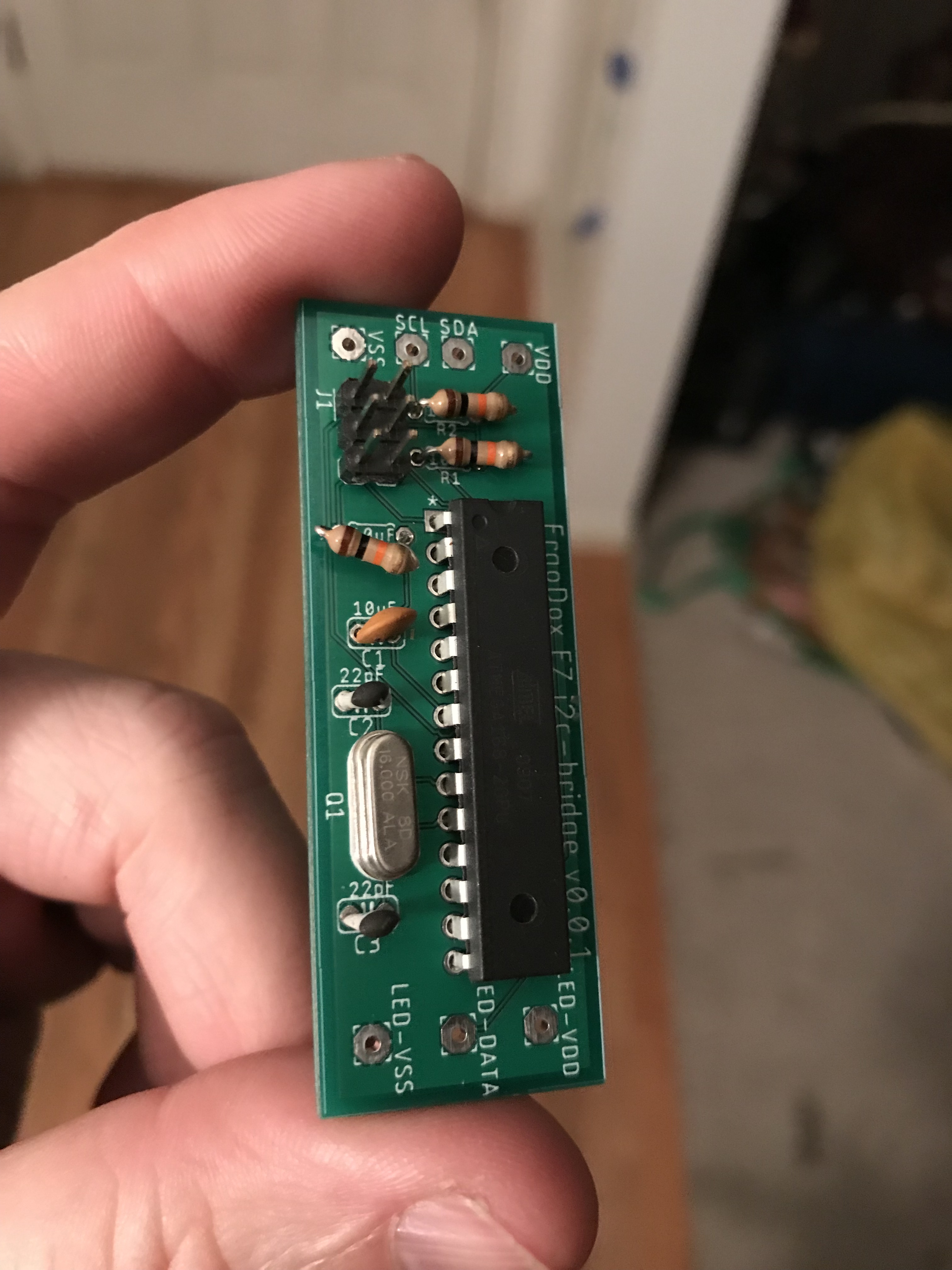
At first I was using PB1 for the LEDs, but that didn’t work for a yet unknown reason. So I instead soldered the led data pin to PB2, and that works fine.
Unfortunately the non-SMD version doesn’t fit into the tight enclosure of the ErgoDox EZ, so I’ll need to do a new revision which probably will be all SMD to ensure a proper fit.
so 5 CAD for the components and another 12 CAD for the SMD PCB.
If anybody wants to build the same mod or follow along - I still have 2 LED strip PCBs flying around as well as a number of I2C SMD PCBs. Ping me and I’m happy to ship them in exchange for shipping fees + component price according to mouser.ca
 ️
️