Ganymede: an ARM based split, ergonomic keyboard

I ordered the prototype for the cherry mx case from 3dhubs.com today - it is supposed to ship by 5th of July and will probably arrive together with the PCBs from JLCPCB. 3D printing all parts at 100% infill and 100μm resolution using FDM cost ~90 USD.

I had to make a couple of changes compared to above revision. 3d printing apparently can not reliably create threads smaller than M5. So I ordered heat insets from mcmaster.com to get M2.5 screws to work.
This version includes tenting mounts on the sides and the Ergodox EZ tents should work.

Unfortunately the TRRS jack is 5mm high so I had to extrude the frame to hide the jack inside the enclosure. As I’m planning to also make a case for choc and kailh X switches I’ll probably have to accept that the connector is exposed for those switches as the enclosure will be less than 5mm. Or find an alternative to TRRS to connect the halves. Or find a different placement for the TRRS connector where the exposure doesn’t matter too much.

Below some rendered images - I will post some real pictures taken with a macro lens once the prototype case is assembled.

left side


right side


parts

  • 13x M2.5 heat insets
  • 10x M2.5 screws
  • 3x Ergodox EZ tenting feet
  • left & right upper body
  • left & right bottom plate
  • left inset for layer indicator LEDs

vertical stackup

  • 1.5 mm extrude around switches to allow TRRS enclosure
  • 1.5 mm switch plate
  • 3.5 mm space to PCB
  • 1 mm pcb
  • 1.85mm hotswap sockets below PCB
  • 0.15mm space
  • 1mm bottom plate

all in all 10.5 mm in height. For a choc version I expect 6.5mm and 4.5mm for X one.

I left a 0.05mm - 0.1mm margin around some components (PCB, OLED, TRRS, USB-C) to ensure the components can actually fit into the case - looking forward to seeing how this turns out in real life.

Also, I have a couple of open questions about 3d printing fully enclosed cases; how much infill is required to get a sturdy case, how thin/ thick do I need to make walls etc etc. If anybody has resources specific to keyboard cases I’d love read about them, as the 100% infill I picked to be on the safe side increased the price for the prototypes considerably.

2 Likes

Everything arrived today - I managed to completely solder and assemble the right hand side so far. First some pictures, and then some learnings:

right hand side top & bottom (PCB only):


right hand side assembled in case:


Some things went really well:

  • the heat inserts/ nuts work really well. they are easy to insert and give the case a solid feel when everything is screwed together
  • the PCB fits into the case, including TRRS jack
  • I left standoffs in the inside of the case which prevent the PCB from sliding too far in; this sandwiches the PCB nicely between top and bottom; the missing holes in the middle of the PCBs are not noticeable from a stability perspective
  • the RGB LEDs I used can be quite bright;

Some things I got lucky with:

  • the 0.5mm margin around the PCB is too little. The PCB fits into the case, but just barely. 1-2mm around the PCB are a minimum
  • the bottom needs a margin too! without the screws on the side I’d get waves in the flexible material.

Some times I didn’t do so well at:

  • the TRRS needs roughtly 4mm space for nicer cables to fit in. I only gave 1.5mm, so I can only use very thin TRRS cables
  • I forgot to add standoffs inside the case, on the left side of the case. So when I press the PCB in, it only stays at the right height on one side.

For the choc & x versions I’ll ditch TRRS in favor of 1mm JST connectors, as the 5mm are too high for the case, but still, knowing how much room to leave would have been useful.
Also, I disliked the surface finish of the 3d printed case so much that I sprayed mine with color filler and a black matte finish. Unfortunately I’m pretty bad at it, so the surface looks rather rugged… Also, the 3d printed case is super lightweight. I’m looking forward to heavy metal case eventually.

Hopefully I’ll find time to solder the left hand side over the weekend so I can post complete pictures. Soldering 1.6mm RGB leds is quite time consuming…

3 Likes

Managed to finish the left hand side too. Again, pics and then some details:

pictures

left hand side

fully assembled keyboard

The tent feature is not ready yet as I’m waiting on M3 nuts - without them I can’t attach the tents. So I can’t show the underglow right now :frowning:

The software is very custom again, as QMK doesn’t seem to support two IS3733 right now. I hope to push the current code, schematic and gerbers to the github repo in the next weeks; I just need to clean up a bunch of things.

Ganymede v0.4 summary:

  • 2 PCBs now (no longer flippable)
  • fully per-key RGB support
  • RGB backlight

I got the breakout board for the RGB tft, so I can start working on v0.5 once I’ve updated the github repo.

v0.5 will focus on choc support, RGB tft display as well as a separate 1Mb eeprom (M24M01) to allow dynamic layout changes, similar to how VIA works today.

I’ll post final pictures with tenting once the nuts arrive :slight_smile:

5 Likes

last update for the rev 0.4 I think: the M3 nuts arrived - the tents from the Ergodox EZ work. However, I missed that the EZ has like a raster on the sides for the legs to snap into a position, so the tents are not 100% solid without screwing them in super tight.
However it’s still solid enough to type on them:

rev 0.4 assembled with tents

auto breath via IS31FL3733:

Aug-17-2019%2019-00-30

I still need to do a lot of software changes for this revision, mostly to integrate the per key RGB. Also looking at the backlight breath I wish the two ISs were running in sync.

Lastly, I realized that a single key doesn’t work with the bottom plate screwed in - it seems the metal nuts somehow short a single line; The issue is that the case frame is too slim. That needs to be changed in the next rev to ensure the threaded inserts don’t touch the PCB.

5 Likes

Been following this for a while and I have to say that a Helix version of this would be pretty endgame ™.

1 Like

Hi. Great design. Will you be making this project open source?

1 Like

Welcome @JASM! It is open source already. See GitHub - nicolai86/ganymede: the Ganymede keyboard. An ARM based, split, ergonomic keyboard

The repository contains everything - schematics, gerbers, stls for the case, and the QMK code to make it work.

3 Likes

What software did you make that with because KiCad won’t open it.

the schematic and board were designed using Eagle (you’d need the Standard subscription to edit the files due to the board size) and the case is designed using Fusion 360.

Still working on the TFT display integration. However, I really wanted a choc hot-swap version, so I made a new revision with only minor changes; the TFT will have to wait until I finish the X-Switch version I guess.


Changes to rev 3:

  • dedicated I2C eeprom chip for VIA/ dynamic keymap support
  • choc hot swap PCB
  • 6P JST SH between halves to have pass SYNC and INTB from the ISSI to the master side
  • 6.5mm total case height! With switches and keycaps installed it’s ~13mm top to bottom (yep, slim!)

As for the case design I learned from my mistakes - bigger gaps around everything, the PCB slides right into the case, it fits perfectly.
The case was created using SLS as 3D printing method with Xometries Media Tumble & Dyed Black finish. And oh my god, it feels amazing, and looks great in my opinion. I’m really glad I chose this printing method and finish.

I haven’t soldered anything yet - I’ll post better pictures from a macro camera once I’m done soldering & installed the tenting kit. Also, I can post comparisons between the choc and mx case then, in preparations for the grand finale: a fully enclosed metal case for my X-Switch edition of the keyboard.

6 Likes

50 % build progress is done - left side works fine. Again, some pictures, then again some learnings.

assembled left side


compared mx and choc version

with front-and backlight on

bottom

animated
ezgif-4-fe37e5fd93f5

Now off to the learnings:

  • JST SH as outside interconnect is a probably a poor choice. even with superglue the connector breaks off easily; it needs support from the top to be used as an outside connector.
  • I’ve cut an EVA foam sheet to be placed between the case and the PCB, and it dampens the typing sound. I like it a lot this way
  • I’ve used lock washers to tighten the EZ tents, and it works really well

I’ll post more pictures when I’m done with the 2nd side.
Oh, and did I mention, 6.5 mm total keyboard case high is super thin and amazing - and 13mm total height is, well also nice to type on.

3 Likes

so, both sides are finished and fitted into their respective case. here is how the finished build looks:

It’s my very first choc experience. I bought linear choc brown switches; usually I use tactile switches, so it’s quite a change, but it feels good.

In any case, now off to add support for ad-hoc keymaps using the eeprom which has been added in this revision :slight_smile:

5 Likes

Awesome work! I’m glad that this is opened source and I always wanted to dive in deeper to the advanced PCB side of things but I don’t even know where to begin… I would appreciate if you could a guide on how you debugged/developed your per key RGB via IS31FL3733 in QMK or any other feature in general because I want to learn as well!

I hope you find this useful. I made this 100% open source because of the great example of the ErgoDox EZ (supportive folks, :heart:),

I can document the steps I took to get things working with QMK. EEPROM Integration with QMK is still fresh in memory, so I can write that down and then circle back to per key RGB.

Note though that none of the code is up-streamed, so what I’m doing will most likely not reflect what needs to be done to get your keeb merged into the QMK repo.

Eventually I want to replace the QMK firmware with one written in Rust or Go, so I have no plans of keeping QMK compatibility for ever :slight_smile:

3 Likes

I’m following your project for quite some time now and wow…
The work, decication and results are simply astonishing!
You have in your hands a pretty nice and compact ortho keyboard :slight_smile:

A good bunch of keyboard PCBs are still using ATMEGAs (so is the one I made), how is the difficulty of using an ARM chip compared to an atmega32u4 for example?

2 Likes

Thank you so much, having a step-by-step guide is a tremendous help for newcomers to learn or even implement something new. I’m totally fine with the code not being up-streamed or being QMK compatible forever and I respect that decision, it’s your project so pursue your interest!

This is rather long, but it’s a first shot at how I went about adding EEPROM support:

On the weekend I wrote some code to integrate a M24M01 EEPROM with the Ganymede. The M24M01 is an I2C enabled EEPROM which supports fast mode plus (up to 1Mhz I2C), which is important for Ganymede because that’s the speed at which the two halves communicate.

The schematic is fairly straight forward, which makes for a great example because it’s easy to get it right the first time:
05

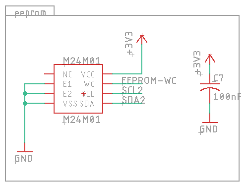
For more complex components I’d start by designing a dedicated prototype PCB and probing with a Raspberry PI but this is simple enough to directly start onboard with QMK.

I start with two empty files, m24m01.h and m24m01.c, and I all I want to see for now is if the device is ready.

m24m01.h

#define M24M01_WC_PAD GPIOC
#define M24M01_WC_PIN 13

// per datasheet, if E1 and E2 are pulled low
#define EEPROM_ADDRESS         0x50
#define EEPROM_LONG_TIMEOUT    1000

uint8_t init_m24m01(void);

i2c2.c

...
i2c_status_t i2c2_isDeviceReady(uint8_t address, uint16_t timeout) {
    const uint8_t* data = {0x00};
    return i2c2_transmit(address<<1, &data[0], 0, timeout);
}
...

m24m01.c

#include "m24m01.h"

uint8_t init_m24m01(void) {
    palSetPadMode(M24M01_WC_PAD, M24M01_WC_PIN, PAL_MODE_OUTPUT_PUSHPULL);
    palSetPad(M24M01_WC_PAD, M24M01_WC_PIN);

    return i2c2_isDeviceReady(EEPROM_ADDRESS, EEPROM_LONG_TIMEOUT);
}

Now that I want to use this in my keyboard I change the rules.mk to include the source file:

ganymede/rev3/rules.mk

SRC += ../m24m01.c

this should already compile, but it’s not used anywhere.

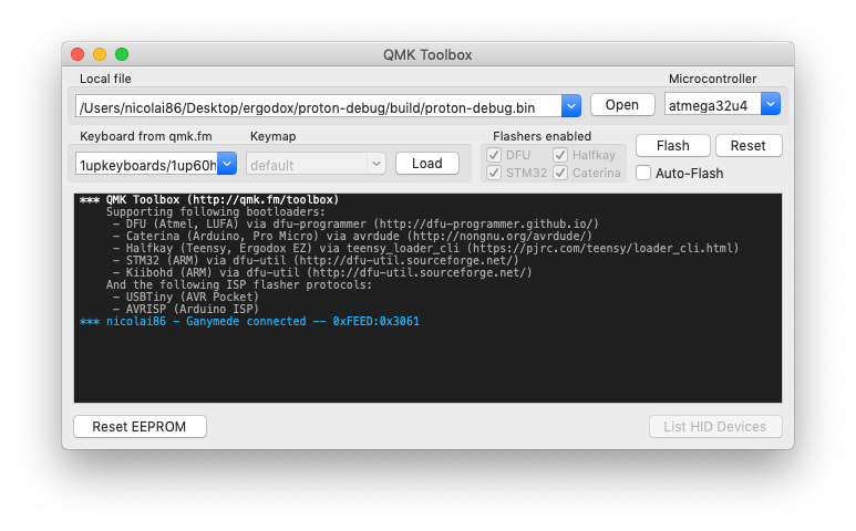
For debugging I like using CONSOLE_ENABLE = yes, because then I can use the QMK Toolbox application to peek at debug output:

Now I add a custom key code to my keymap, which triggers the new code:

ganymede/rev3/keymaps/default/keymap.c

#include "../../../m24m01.h"
...
#define KC_EEPROM_RDY KC_F20
...
bool process_record_user(uint16_t keycode, keyrecord_t *record)
{
  ...
  switch (keycode) {
    case KC_EEPROM_RDY: {
      if (record->event.pressed) return false;
  
      uint8_t result = init_m24m01();
      if (result == 0) {
          xprintf("M24M01 ready\n");
      } else {
          xprintf("M24M01 not ready: %d\n", result);
      }
      return false;
    }
  }
}

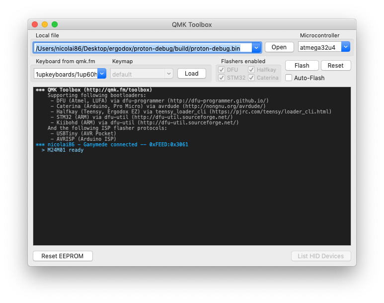
I flash my prototype, hit the right key on the right layer - voila:

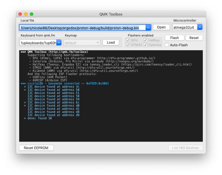
Now you might not be so lucky that you know the I2C address; in that case, I have custom code to scan for I2C devices, bound to another key:

    case KC_I2C_SCAN: { 
        if (record->event.pressed) return false;
        uint8_t error, address;
        uint8_t numberOfDevices;

        numberOfDevices = 0;
        for(address = 1; address < 255; address++ )
        {
            error = i2c2_isDeviceReady(address, EEPROM_LONG_TIMEOUT);

            if (error == 0) {
                xprintf("I2C device found at address %x\n", address);
                numberOfDevices++;
            } 
        }

        xprintf("done: found %d\n", numberOfDevices);
    }
    return false;

At this point I know that I have established communication with the device, and I basically need to flesh out the API I want to use to talk to it.
I basically repeat the above steps for the functions I need:

  • add a new keyboard code on a dummy layer
  • bind a new function to that keycode
  • flash, try, debug
  • repeat

In the case of the M24M01 I added 5 keys, all following more or less above steps:

  • dump an entire page (to see if my page_read function works
  • batch write to a page (so I can batch writes and don’t wear out the EEPROM too fast
  • single byte write at random location
  • single byte read at random location
  • is the device ready? (see above)

Now, every function of course needs to be implemented as per the datasheet.
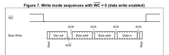
E.g. m24m01_byte_write

uint8_t m24m01_byte_write(uint8_t address, uint16_t eepromAddr, uint8_t data) {
    const uint8_t location_and_byte[3] = {(eepromAddr >> 8) & 0x00FF, (eepromAddr & 0x00FF), data};
    palClearPad(M24M01_WC_PAD, M24M01_WC_PIN);

    uint8_t status = i2c2_transmit(address<<1, &location_and_byte[0], 3, EEPROM_LONG_TIMEOUT);
    i2c2_stop();

    palSetPad(M24M01_WC_PAD, M24M01_WC_PIN);

    // this is a hack - waiting until the device is ready should be done instead
    wait_ms(6);
    return status;
}

which matches the datasheet:

58

Now that I know that the functions work I delete the keycodes, and use the library where I actually want to use it: custom keyboard keymaps stored in EEPROM, configured using raw hid.

But that’s a separate post :slight_smile:

Note above code is not pretty, it’s just a quick and dirty way to get an integration off the ground. I glossed over many parts, but this is the rough direction I usually go;

5 Likes

the biggest challenge for me was that everything is 3.3v now. I did some tinkering with Atmegas and Attinys before, and I was only used to having 5v everywhere. As for the software side, that’s all abstracted nicely behind HAL, so it’s really comfortable to use STM32s, even directly without QMK. I especially like generating dummy projects with STCubeMX to play around with settings; personally I find the developer experience way better. But it took some time to get used to it for sure.

2 Likes

Thank you very much for your answer.
I also played a bit with STCubeMX, really nice piece of software :wink:
STM32 software environment as a whole looks to be extremely well done.

On the project I’m working on I sticked to atmega MCU, but plan to move on ARM MCUs later on :wink:
The advantages that I see is I2C speed (1 MHz on ARM, 400KHz on Atmega), and also the fact that DMA is used on QMK for sending I2C data on ARM while CPU is used for Atmega.
Looks to be much better to handle lots data though I2C, like RGB leds on your project.

What I don’t know yet is if ARM I2C DMA process is asynchronous or not.
Would be nice if it was, because sending RGB leds data takes quite some time though I2C even at 1 MHz, and in case this is synchronous the firmware can’t handle other important things like matrix scanning for example.

Great job on write up! I’ll need some time to digest it but I’m looking forward to implementing that EEPROM chip for my next project but on the STM32F072 instead.

3 Likes