Build #11: KBD19x
So far, my build adventure has taken me through form factors ranging from an ortholinear to a TKL, and while I’ve been playing a lot with 60s, and enjoying them, I continue to think of TKL as my endgame form factor. Up until recently, I’ve also been thinking of TKL as the last stop before a full-size board. I mean, what else could you really do to grab some desk space back from that full-size board, other than lopping off the numpad?
Cue a suitably reverberant voice of omnipotence: you have much to learn, my son.
Yes, back in build #6, I had a near-miss with “TKL+5”, the idea of inserting the “missing” five 1u keys into the space above the arrow cluster. But even then, somehow the idea of moving the numpad to the left and throwing the intervening keys away, rather than throwing the numpad away, just hadn’t occurred to me. With the popularity of 1800s on the rise, though, it was only a matter of time until I saw one and the light bulb went off. And, there is something kind of interesting about jamming an arrow cluster back into the space between the numpad and the alpha cluster - it seemed ugly at first, but it’s growing on me.
Finally, whether or not I liked the 1800 experience, I’ve been finding that doing builds with different form factors is a great way to challenge my build skills, as well as my firmware skills. So I was excited to try something in the 1800 space, and after poking around to look at build alternatives, I eventually settled on the KBD19x kit. It’s a little weird in that it’s not quite a true 1800 (it’s missing the four-key delete row that you’d see on a G80-1800), but it has an extra key right after the function keys, where an LED indicator trio might normally be. Still looks like a good time.
The only downside here that I could see was the lack of support in the GitHub QMK repo. After the initial QMK experience in build #6, adding layout support for the Phantom “TKL+5” to the repo, and looking at all of the amazing functionality @drashna has built in his userspace configuration, I became very interested in building out a shared set of key mappings and macros for all of my boards. While the KBD19x is nominally supported by QMK, that’s through a separate web configuration tool, not via the standard repo, which for me was a problem. Having invested the time to standardize my mappings across the rest of my boards, I didn’t want to have to deal with a special snowflake - I wanted to build the firmware for all of my boards in as standardized a way as I possibly could. After spending some quality time with the QMK documentation, I made a decision: if KBD19x support isn’t in the repo by the time I need it, I’ll add it. Hopefully that wasn’t a crazy idea?
And, let’s be honest. There is one more reason to like these somewhat larger form factors. When you drop serious coin for a quality keycap set, it’s kind of a shame when a substantial fraction of the set goes unused on a smaller board. Would that concern ever really stop me from going with a smaller board? No, it wouldn’t, but I’d be lying if I said that I didn’t think “nice, I’ll get to see more of that keyset on this build.”
Switch treatment
After the switch lubing experiences during the “geek arts-and-crafts” series, a little internal dialogue takes place every time I need to prepare switches for a build.
Me: Ugh, I have to lube all these switches. There goes the better part of a day. Do I really have to do this?
Me: You suck. Have you completely forgotten how nice it is to type on lubed switches? Man up.
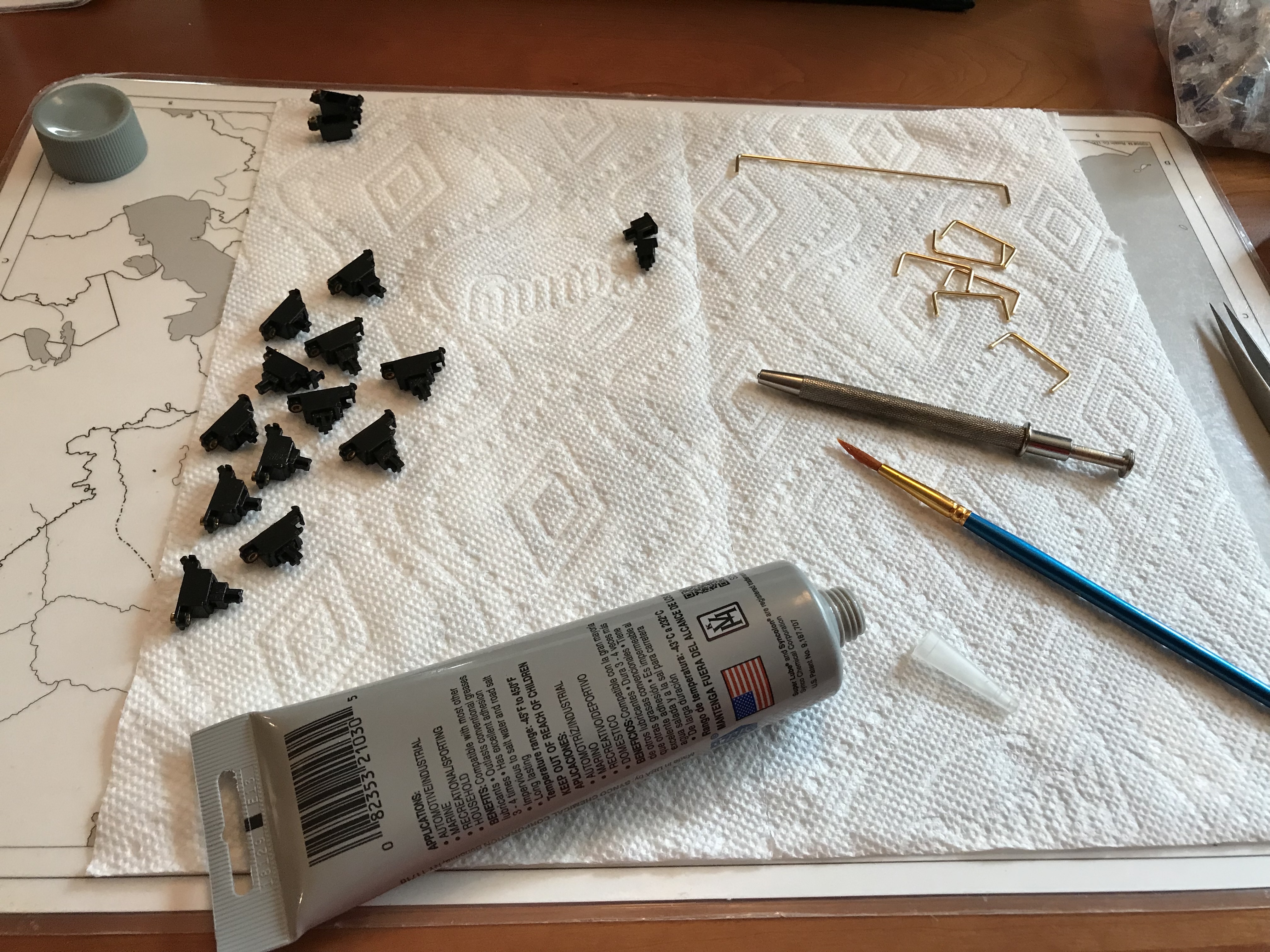
Properly self-chastened, I got comfy, fired up a long playlist, and got to work. I found it best to do these in batches of 15, the width of my acrylic switch lubing station. This made it straightforward to lube assembly-line style, and it also gave me convenient breakpoints for standing up and stretching my legs. As it happened, real life intruded, so the task ended up getting split over a couple of days. But, eventually, I had a little plastic bin full of 100 lightly lubed Zealios.
Stabilizer treatment
The received wisdom is clear. GMK screw-in PCB-mount stabs, or death. There can be only one. But on inspection, the stabs that came with the KBD19x kit honestly didn’t appear or feel appreciably different from the GMK screw-ins. Not wobbly, or at least no more so than any other stabs, including GMK, that I’ve tried.
While I had spare GMK sets I could have used, after some momentary waffling I resolved to go ahead and use the OEM ones.
In a previous build log, I was excited to try the full @Walkerstop upstroke silencing mods on PCB mount stabs, but his comments in response to that log gave me pause. Apparently others had reported that after doing this mod, keycap removal caused the stabs to pop right out. That mod has two departures from the “standard” stabilizer treatment: clipping of all four legs on the sliders, and O-ring insertion. It seemed to me that eliminating all four legs would have to be the reason for the sliders to pop out, so I opted for a partial upstroke silencing treatment: only clip the usual two legs of the slider, but do the O-ring insertion. As it happens, the two legs we would normally clip were already gone from the sliders of these OEM stabs.
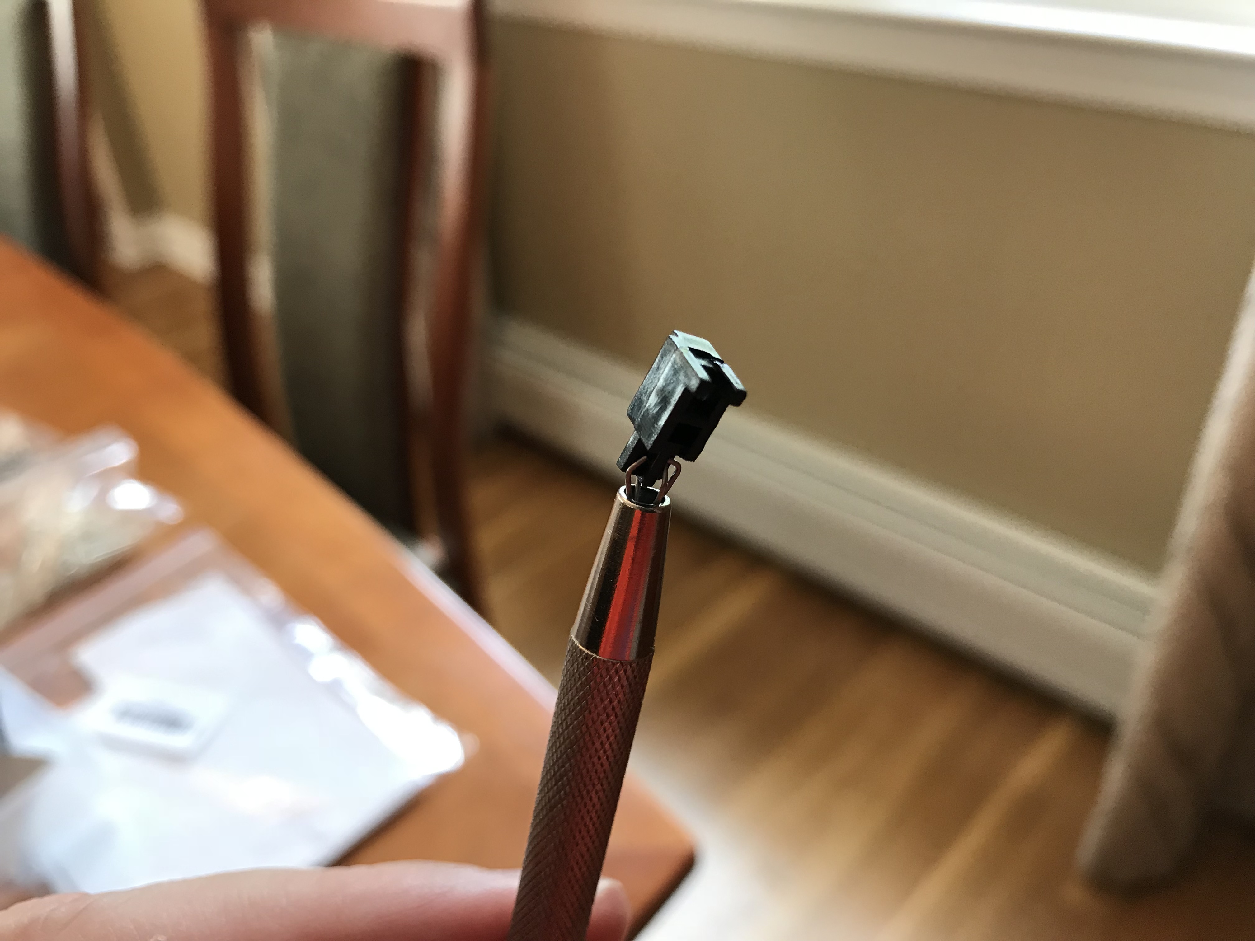
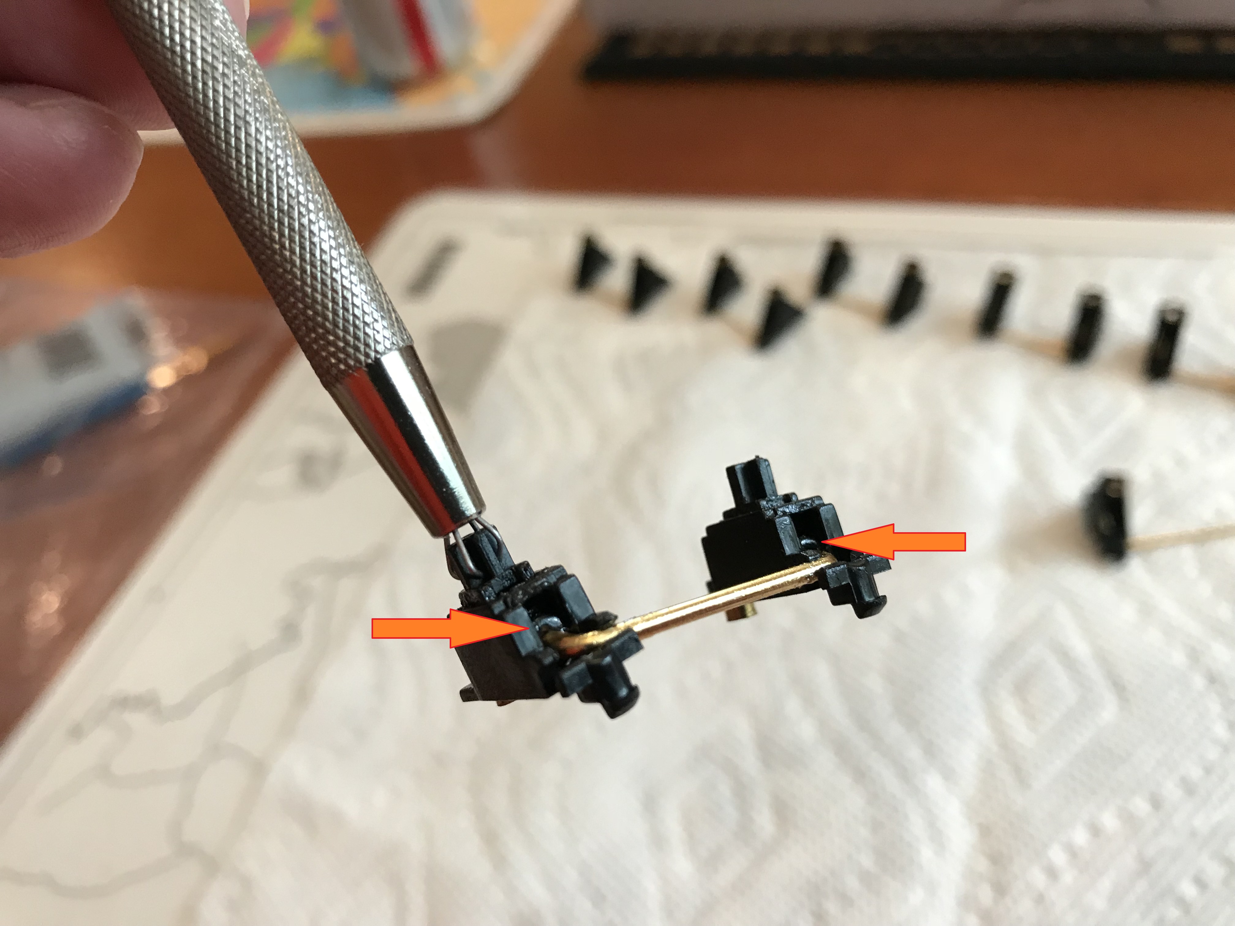
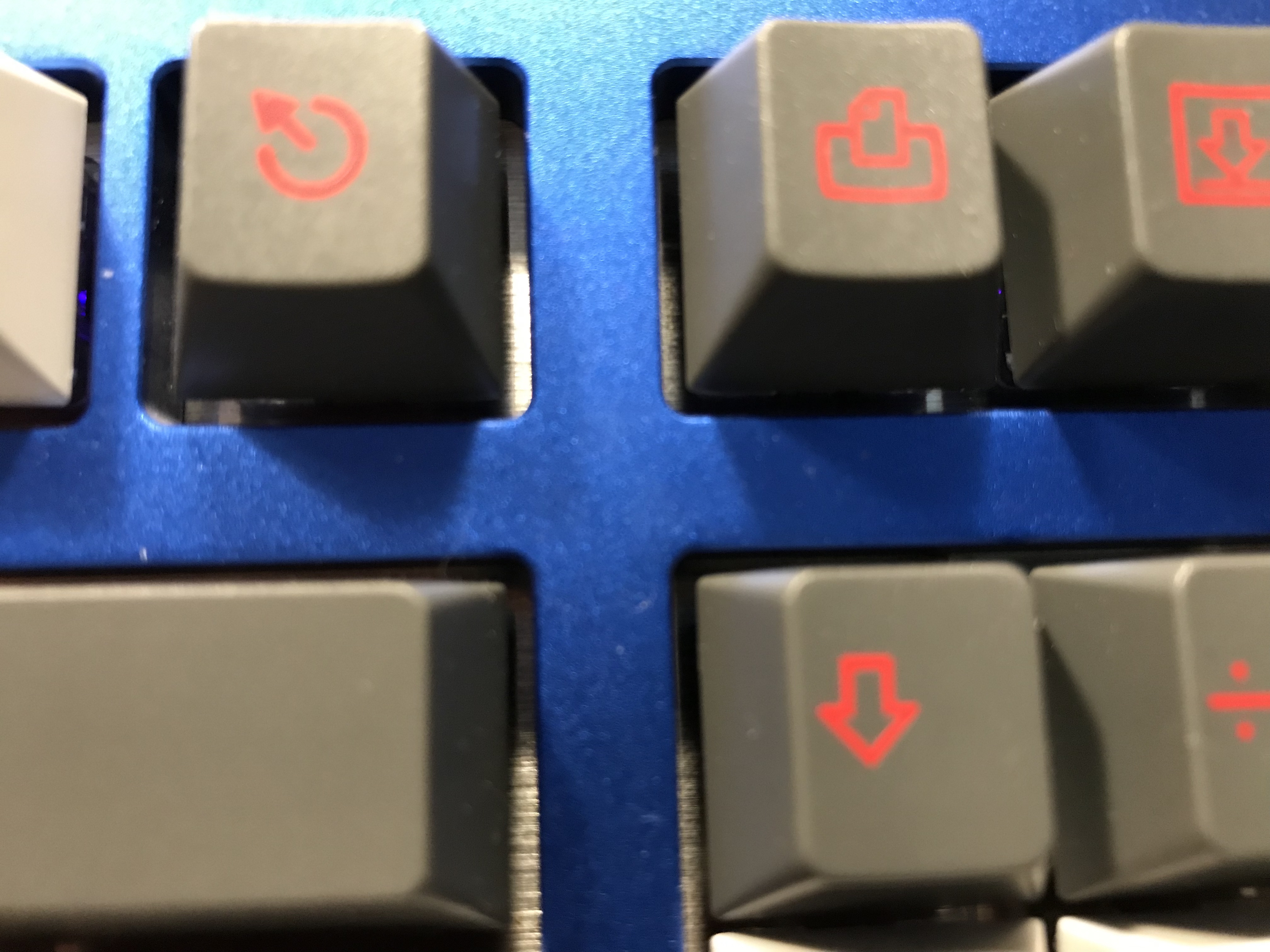
So, the job just boiled down to the usual SuperLube treatment, and some careful tweezer work to get the O-rings into the stabilizer housing and threaded onto the stab wires. Here’s what the O-ring placement looks like when the stabilizer is put back together, from a couple of different angles:

After a quick bandaid-style mod with adhesive silicone pads, the stabs were ready to be mounted. The KBD19x kit came with plastic washers for the screws, which was a good thing since the PCB looked very much as though it was designed and manufactured by the same group as the DZ60, and if you read previous build logs, you’ll remember that I have had issues with stab screws shorting out traces on that board. So, having washers at the ready to guard against those problems is nice, although it’s worth noting that some of the installed washers overlap the edge of the PCB, and one even bends up over a diode that’s within a washer’s radius. Not so great.
Sorbothane, part 1
You will have seen by now that I like Sorbothane for sound dampening applications. You’ll also have seen that I’m still on a quest to properly dial in its usage for keyboards. One of the problems I’ve been wrestling is getting strips of the right thickness to sandwich between the PCB and the plate. Too little thickness, and the Sorbo can’t touch both the plate and PCB, reducing its effectiveness for sound dampening. Too thick, and undesirable excess pressure will be applied to the plate and/or PCB when the sandwich is assembled.
In another thread, I estimated 4mm as a reasonable thickness for Sorbothane when sandwiched between a standard 1.5mm plate and the PCB. That thickness isn’t currently readily available, but we can approximate it, to some extent, by cutting 4mm strips from thick pads of Sorbothane. I used a metal ruler to first mark off a bunch of dots 4mm away from the edge of the Sorbothane pad, and then I used the ruler to connect the dots and trace a cutting line with a ball-point pen (pro tip: leave the protective plastic on the Sorbothane pads while you do all of this, so you don’t have to worry about sticking to the Sorbothane). Then, just cut down the line as best you can. I used 0.25" (6.35mm) thick pads of Sorbothane as my starting point, and once I had enough 4mm wide strips, I just laid them on the plate on their sides.
How did I know if this was doing anything useful? Before-and-after tap testing, which is pretty much exactly what it sounds like. Before layering in the Sorbo, put the plate and PCB together with a few switches, and tap the plate with your finger and/or fingernail, all around the plate, while holding the whole assembly close to your ear. Listen. Then, after putting Sorbo on the plate where you want it to go, repeat the process. If your experience is like mine, you’ll hear a high-frequency ringing with your fingernail on the plate before the Sorbothane application, and that will go away almost completely even with a few strips of Sorbothane in place, leaving a more bass-heavy thunk. Whether this is an improvement is a matter of taste, but for me, it’s very much an improvement.
It’s also nice that only a few pieces were needed to eliminate the lion’s share of the high-frequency plate noises. Sorbothane isn’t the cheapest option out there, so it’s nice to be able to stretch the supply through more builds.
Porting to QMK when it’s kind of ported already
With the PCB/Sorbothane/plate sandwich lined up, switches were mounted and soldered, and the keyboard was flashed with an initial hex file built with qmkeyboard.cn. A few minutes with tweezers and a keyboard tester web app, and the initial build is functional.
I said I was going to do it, and it’s time: let’s build out support for KBD19x in the QMK repo. On the plus side, I’m intimately familiar with C/C++ in a variety of application domains, and the QMK documentation for doing a keyboard port looks pretty complete and easy to follow. On the down side, none of those application domains included embedded programming, and none of my version control experience included git. So, there’s still going to be a learning curve here. Time to get stuck in.
First of all, for QMK to support a PCB, it needs to support the controller. The controller is the chip on the PCB that does the matrix scan (more on that in a moment). While I’m willing to attempt a port for a controller that QMK already knows about, I’m pretty sure that writing core support for a new controller is currently beyond my pay grade, so I need to confirm that the controller is one that QMK already knows about. I’m 99.9999% sure that must be the case, since the qmkeyboard.cn site claims QMK support, but I’m me, so I check the chip anyway. Atmega32U4, yes, we’re good.
Next, the wiring matrix and the matrix scan. As I understand it, the controller on a PCB determines key activity by repeatedly lighting up one row of the matrix with some current, and then seeing which columns also show current coming through when that row is turned on. Those row-column pairs correspond to switches that have been depressed to allow current to flow through. The controller keeps track of those row-column pairs, turns off the row, lights up the next row, and repeats the process. When this process has been executed for every row, that’s called a matrix scan, and the controller does that scan many times per second to track key presses and key releases. For the controller to “know” which row-column corresponds to each switch, it needs to know which key corresponds to each row-column coordinate pair in the wiring matrix. It stands to reason that the firmware we build must include a description of the wiring matrix, in order to properly translate row-column pairs into the correct keys. So how do we figure out what the wiring matrix is?
If I was really porting a keyboard from scratch, with just a PCB in my hand, I’d have to work out the wiring matrix for the keys by visually inspecting where the traces connect to the controller. Even under a magnifier, this would be painful - the traces are the same color as the PCB (for this PCB, anyway), they’re very narrow, they’re often in close proximity to one another, and they can pass through to the other side of the PCB to “jump” over other traces without forming an electrical connection.
Fortunately, I was able to bypass the bulk of this pain. The qmkeyboard.cn site actually provides a “Wiring” tab which not only shows the wiring matrix for the boards it supports, but also shows the row and column for a key when the key is clicked. So, I started by manually recording the row/column pair for each key in the web interface. In the QMK code, this information is recorded in a LAYOUT macro for the keyboard, which provides both the wiring matrix for firmware compilation, and provides a nicer interface for subsequent QMK developers. With a LAYOUT macro, you can stare at code that is organized like the actual keyboard layout, rather than the rat’s nest of a wiring matrix you’ve been staring at. It took a little time to build out this macro and double-check the mapping from keys to row-column pairs, but it’s more careful bookkeeping than anything else.
Similarly, the website provided pin assignments for backlighting and RGB control, as well as available memory limitations for the controller - all information that QMK needs to compile a complete firmware for the board in the form of a .hex file. Again, this isn’t hard per se, but it requires due diligence to make sure the correct information is being coded. Again, I need to give a shout-out to the QMK docs. Descriptions of the required information, and how to supply it to the code, were quite clear, at least to this C developer. Love that.
After fixing a couple of typos, and checking all my data entry again, the code compiled cleanly, and there’s a brand-new .hex file for the KBD19x. Oh boy. The reported memory sizes are good, so this should easily fit on the Atmega, and there are no errors, and I’ve triple-checked all of the information, so there’s no reason this shouldn’t work. Still, oh dear. I just sat for a few minutes thinking it over before finally committing and flashing the firmware to my PCB with QMK Toolbox. Looks like the PCB is still alive? Time for the keyboard tester and tweezers again…
If plugging in Build #1 and having it actually work was the single best experience I’ve had with this hobby to date, then flashing the firmware for this kind-of-reverse-engineered port to QMK and finding that it worked, first time, certainly qualifies as at least a very strong second. Damn, that was satisfying. I’m going to go have a celebratory glass of wine. Be back in a moment.
Full disclosure: while the firmware really did work, I discovered later that the .json file I provided for key position and sizing wasn’t showing up correctly in QMK’s own web configurator project. But before I realized I had a problem, let alone worked out how to diagnose and resolve it, @noroadsleft had already found my problem (a stray character in the file) and fixed it. Cheers, buddy.
From here, it was just a matter of process - a pull request, code review and changes, and there we are - it’s in the repo. Cool beans.
LEDs
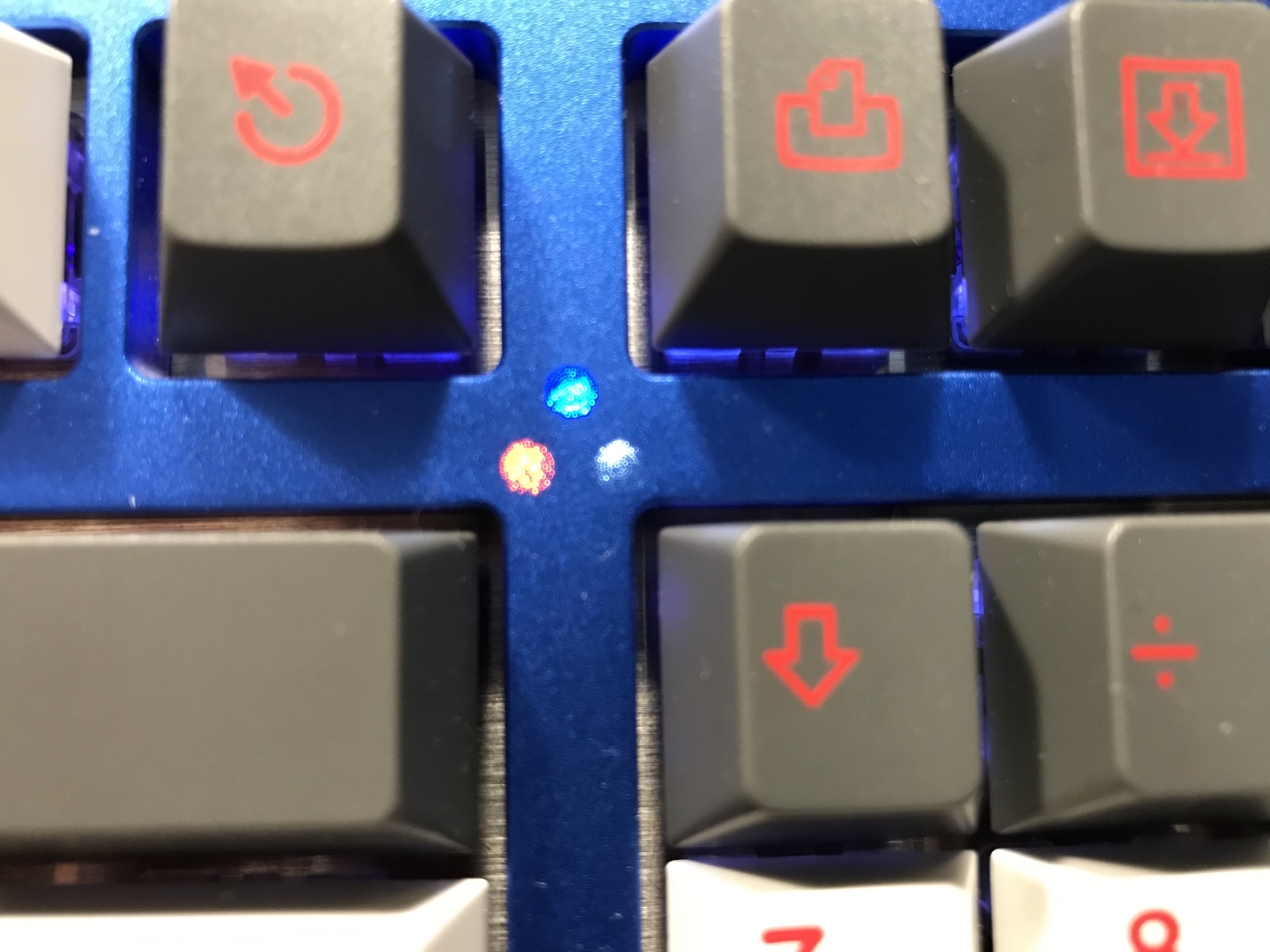
The underglow RGB LEDs are already soldered into the PCB, but it’s up to me to put in LEDs not only for key backlighting, but also for the caps lock, scroll lock, and num lock indicators. The way this is done on the KBD19x is really quite sexy; the case top has three machined “tunnels” in the cross strut in which the LEDs can shine upward, and instead of actual holes at the top, the case is micro-perforated, so light can shine through when the LEDs are on, but when the lights are off, these three spots are featureless anodized aluminum, just like the rest of the case. Nice. I used orange, blue, and white LEDs for these, as that’s what I had on hand.
Now. If you’re doing key backlighting on the KBD19x, and in particular, on both 2u keys on the numpad, learn from my mistake. Normally, I solder in all switches first, and then thread the LEDs through the switches before soldering. But with the 2u numpad keys on the kbd19x, this will not work, because the LED pads for these two keys are not aligned with the holes in the switch sitting above them. Yes, really. Try as you may, you are not going to be able to thread the LED pins through the soldered-in switch and then somehow get them to bend enough to make the necessary turn to reach the pad holes on the PCB for these two keys. Or if you can, I demand video. Because I didn’t detect this issue until it was too late, I ended up having to desolder and remove these two switches, threading the LED pins through the switch holes while the switches were out, and then mounting the switch and threading the switch and LED pins in place and soldering. A nightmare fix?Well, no, but an annoying hassle? Yes.
Sorbothane, part 2
We’ve done the PCB/plate sandwich. Now it’s time to dampen the case. The PCB has the underglow RGB LEDs and an acrylic spacer to show off that glow, so I had to measure out pieces of Sorbothane that would lie inside the imaginary perimeter of the underglow LEDs, as not to obscure all those Rs and Gs and Bs. In addition, I wanted to leave a cutout for the controller, to avoid putting any undue pressure on the PCB at that point. Look at me, all thinking ahead and stuff. Also, taking some measurements to estimate the gap between the PCB underside and the interior bottom of the case, I found that a 3/16" (0.188") layer of Sorbothane, which I already had in hand, would be about right for contact with the PCB and the case, so with a few minutes of measuring and cutting, the case dampening was in place.
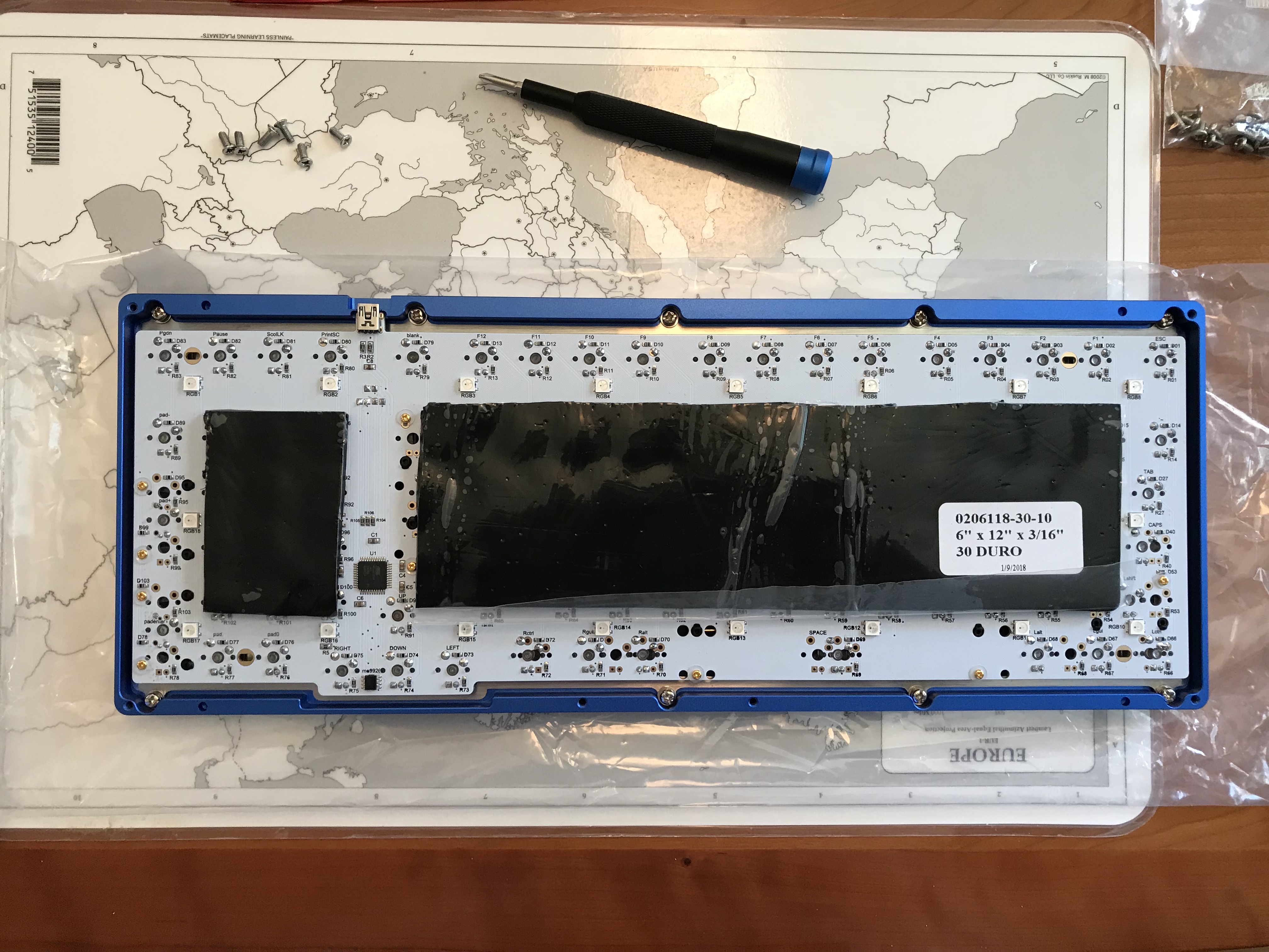
I carefully peeled the protective adhesive layer off of both sides of the acrylic spacer (take your time, the spacer that comes with the KBD19x kit is flexible and fragile). In a nice touch, the spacer has cutouts that align with pegs on the case to assist in placement. From there, it’s just a matter of lining up the other half of the case and screwing everything together.
Sorbothane, part 2b
I threw on a set of caps and tried the board out, and discovered immediately that I had a problem. While most keys felt quite nice and sounded wonderful (switch lube + GMK + Sorbothane FTW), the enter and backspace keys were very sticky, and required undue force for downstrokes. I tried to convince myself this would work itself out, but eventually the conscientious part of me won out over the lazy part of me, and the case was opened again. Note to others - if you have direct Sorbothane contact between the PCB and case, and you find you have to separate them, take your time prying them apart. Sorbothane is quite sticky, and we don’t want to fracture the PCB.
As soon as I separated the PCB and the case, I had the presence of mind to try the enter and backspace keys again, and wait, what? They work now, just fine. Inspecting more closely, I realized what the issue was - the Sorbothane was pressing the clip mount of the stabilizer housing on one side of each of the two affected keys, hard enough to force the stabilizer housings slightly off of vertical, creating excessive friction on the stabilizer sliders. Solution? Cut away more Sorbothane to avoid pushing the stabilizer housings out of alignment.
While I was doing this cutting to relieve pressure on the stabilizer housing, I noticed that one of my Sorbothane squares was actually applying pressure to the reset button on the PCB. I wonder how long it would have been until the board started dropping into bootloader mode for no discernible reason? That’s right, look at me, all thinking ahead and stuff. Sigh. Let’s cut some more Sorbothane, shall we. That’s good.
Probably best not to let me out of the home without adult supervision.
As an aside, with all this aluminum and Sorbothane, this keyboard is heavy. Quite heavy. I wouldn’t want to drop this thing on my foot.
Speaking of weight…
So it’s all put together, and I’m typing, and it’s very nice - the sounds are really pleasing. This is my first time with real GMK caps, and it really is a step up from the cheaper, thinner Cherry profile caps. These yield a lovely soft clack, and with the switch lubing and Sorbothane, that’s all we hear. Nice.
But we haven’t talked about switches yet. I’m in the middle of an experiment - the switches on this board are R11 78g Zealios. This was somewhat unintentional, in that I thought I was lubing 67g Zealios before I noticed, 20 or so switches into the lubing assembly line, that the switches were a bit too stiff, investigated, and realized I was lubing 78s.
I’ve thought that my tastes run to the middle-of-the-road for spring weightings, and I’ve generally felt most comfortable on the 65g and 67g Zealios. However, I wanted to see what I thought of switches with comfortable tactility, but heavier weighting (not necessarily on this build, but what the hell, it was going to happen anyway at some point, so let’s just run with it). On a switch tester, I wasn’t entirely sold with the 78s, but then again, that was a switch tester. I think the switch tester is great for ruling out switches you know you’re not going to like, but for switches you’re not sure about, I think the only real way to be sure is to try out a board with them.
And, initially, I thought that even with the lovely sound and lubed smoothness, these springs were really just a bit too heavy. Normally, I’d just switch back to another board immediately for daily driving at that point, and I’m not really sure why I didn’t do that this time. Maybe I didn’t want to give up the melody of the clacks? In any case, after a week or so, the feel started to grow on me. I found I was bottoming out less often, and riding the tactile bump more often. Even more interesting, after going back to build #1 (TADA68 with 67g Zealios), I ended up switching right back to this board. Hmmmm. Getting all these variables dialed in turns out to be a more subtle optimization than I imagined. That voice. It’s back again…
…you have much to learn, my son…
In the meantime, these keys and that sound? It’s all good. While it took me 10 more builds, and while it may not be endgame, I have a new daily driver. Progress!
Lessons learned
- 78g isn’t as firm as I might have guessed from just playing with a switch tester. I’m enjoying the weight more than I thought I would. Perhaps it’s a good idea to just live with a set of switches for a while…and perhaps I need to get a hotswap board sometime soon for just this purpose.
- I’ve spent enough time with this board and these switches that the difference in weight is less noticeable in an absolute sense than it was before. Not sure if that’s because I’m getting used to the weight, or perhaps the springs are being broken in a bit? Something else to evaluate.
- Be careful when placing Sorbothane. Under sufficient compression, it can push the clip-end of a stabilizer housing and deflect the stabilizer off-vertical, leading to compromised keystroke performance. It’s best to just create cutouts where this might be an issue.
- With that said, the combination of Sorbo dampening, switch lubing, and GMK caps yields a delightful sound, the best of any board I’ve built to date. It’s the sound of hard raindrops on the roof.
- A sparse Sorbothane treatment between the PCB and plate can be remarkably effective for dampening - and cost effective, if you plan to do multiple builds.
- If you’re doing LED backlighting, check the LED pad positioning to be sure the LED can cleanly pass through the switch and through the pads. For any keys for which this isn’t the case, it will be far easier to thread the LED pins through the switch first, before seating the switch on the PCB.
And, a special lesson on color
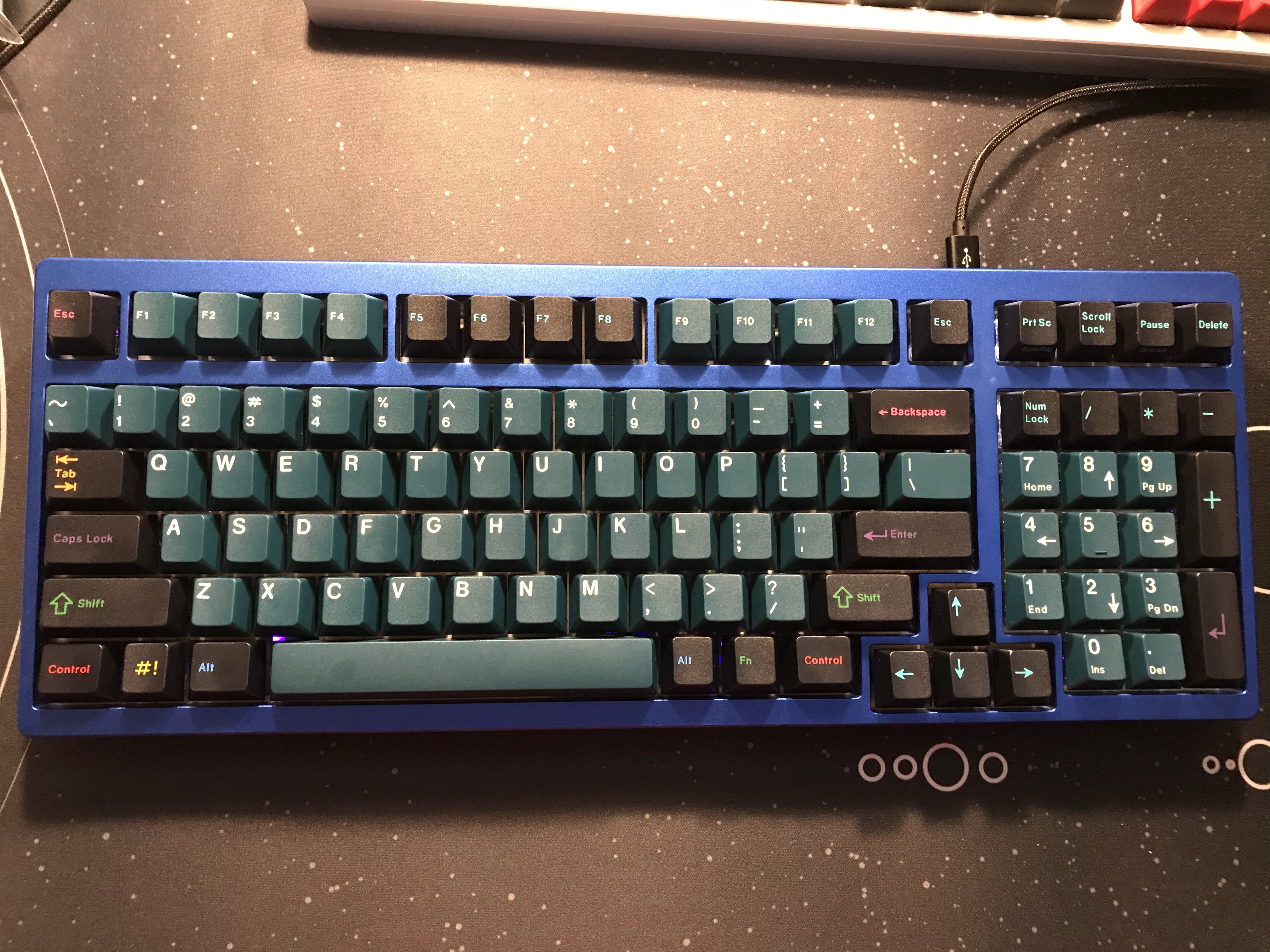
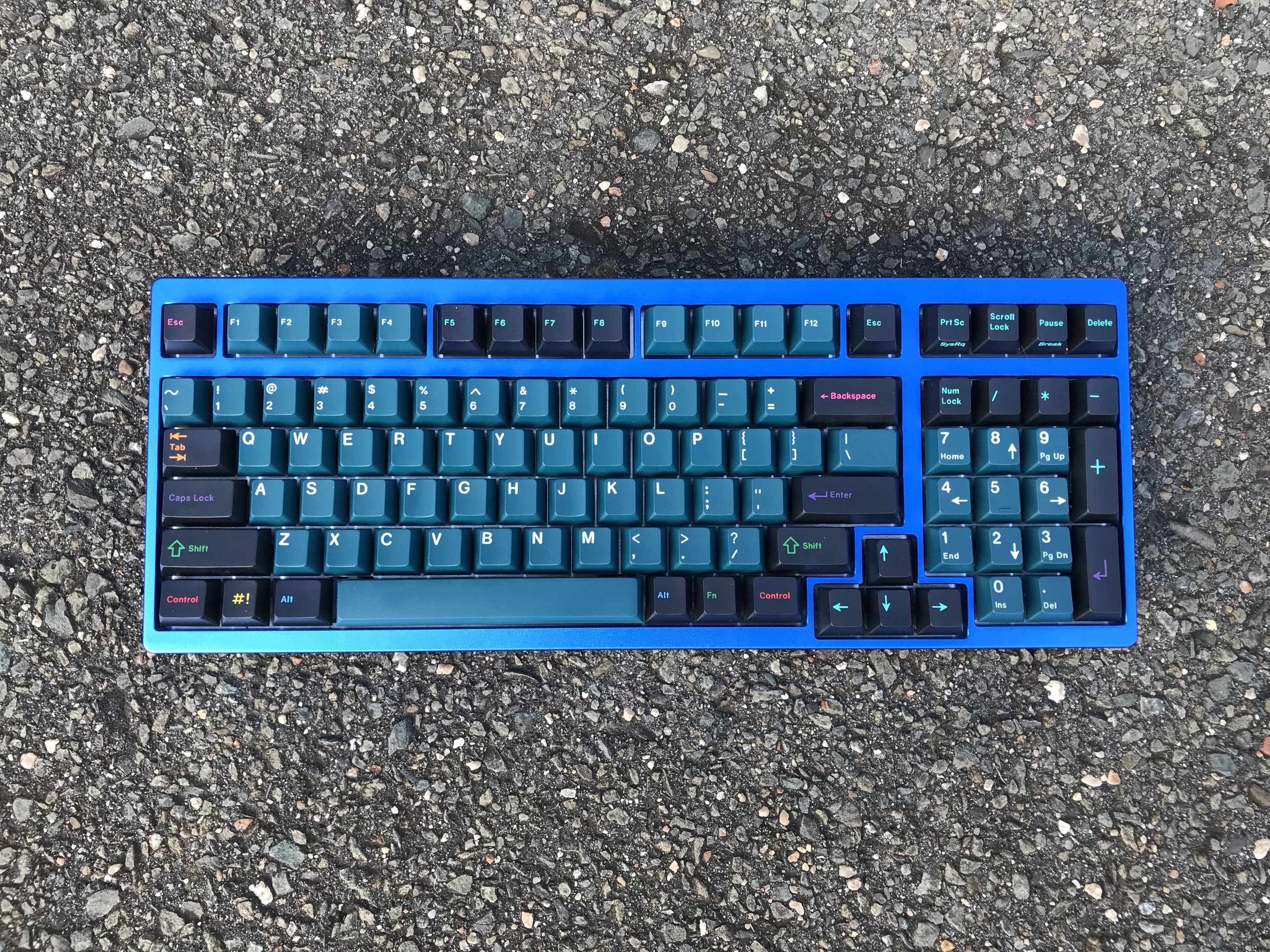
As you’ll see in a moment, I’m getting to the point where I need to think about doing proper color calibration for my build logs. This build had a lot going on color-wise - blue anodized aluminum case, and GMK Solarized Dark for keycaps. Having seen this build in a number of different lighting situations, I understand both why there has been so much drama around the set in terms of color accuracy, and why opinions on its looks are all over the place. Depending on what time of day it is and whether I have lights on in my office, my opinion changes too. This really crystallized for me when I got around to taking and comparing photos of the build. Same board, same caps, same cell phone camera - just different background and lighting. What a difference!
Indoors, under LED lighting on a desk:
Outdoors, under direct sunlight on asphalt:
Specifications
case: KBD19x anodized aluminum (blue)
case dampening: 0.188" 30 Duro Sorbothane, trimmed to fit inside underglow LEDs and away from stabilizer clips and ICs
PCB: KBD19x
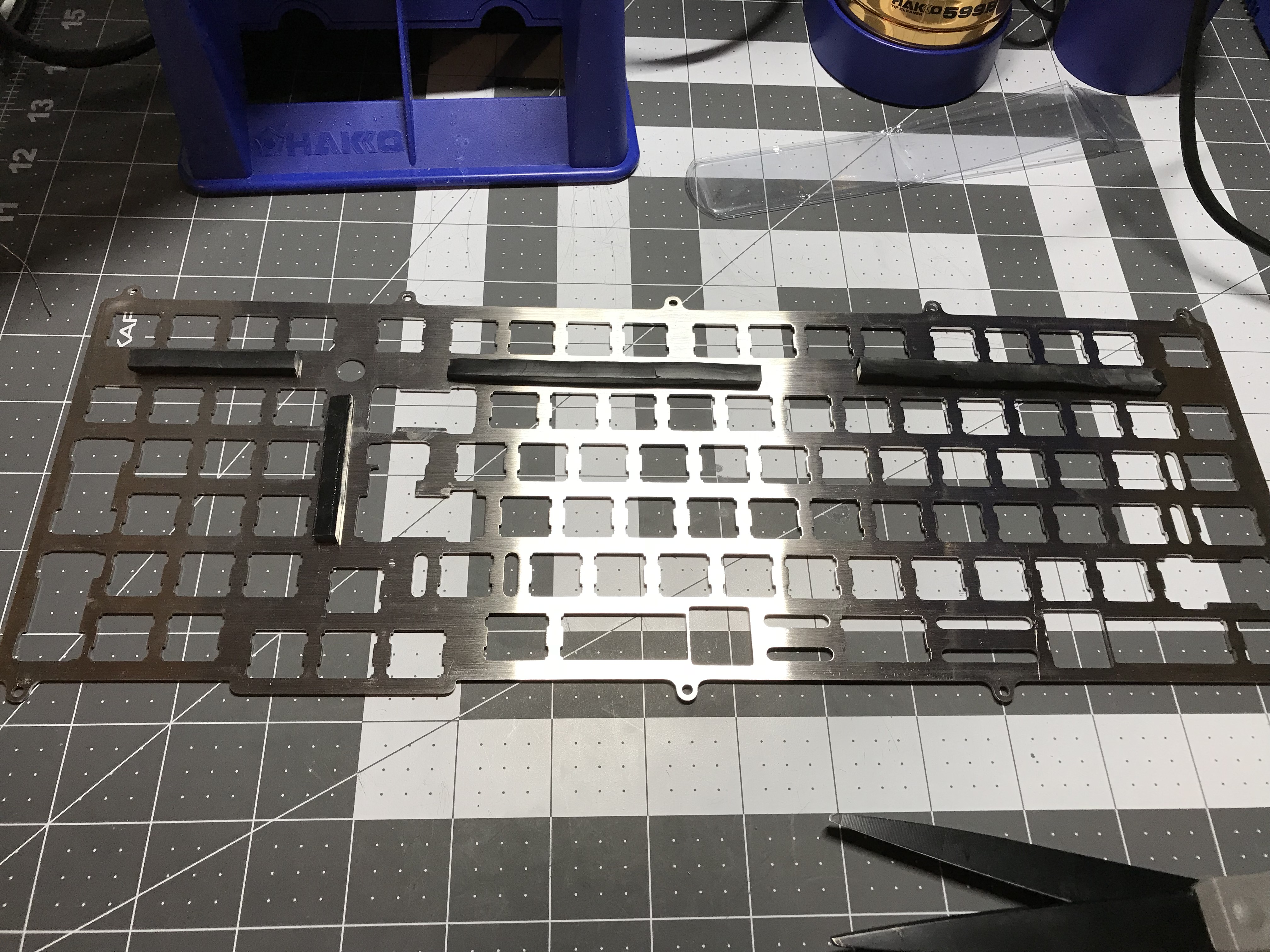
plate: KBD19x stainless steel
LEDs: blue f1.8mm per-key
switches: R11 78g Zealios
switch lubing: Tribosys 3204
layout: ANSI
keycaps: GMK Solarized Dark
stabilizer: OEM screw-in PCB mount, pre-clipped
stabilizer mods: lubed housing, sliders, & wire ends with SuperLube, bandaid-style mod with silicone pads,
O-ring upstroke silencing
plate/PCB dampening: ~4mm wide strips of 0.25" 50 Duro Sorbothane, laid sideways on widest struts of plate
HxWxD (without feet or caps): 1.25"x15.06"x5.75"
HxWxD (without caps): 1.38"x15.06"x5.75"
HxWxD: 1.88"x15.06"x5.75"
assembled weight: 5.30 lbs