Hi, I'm jshufelt

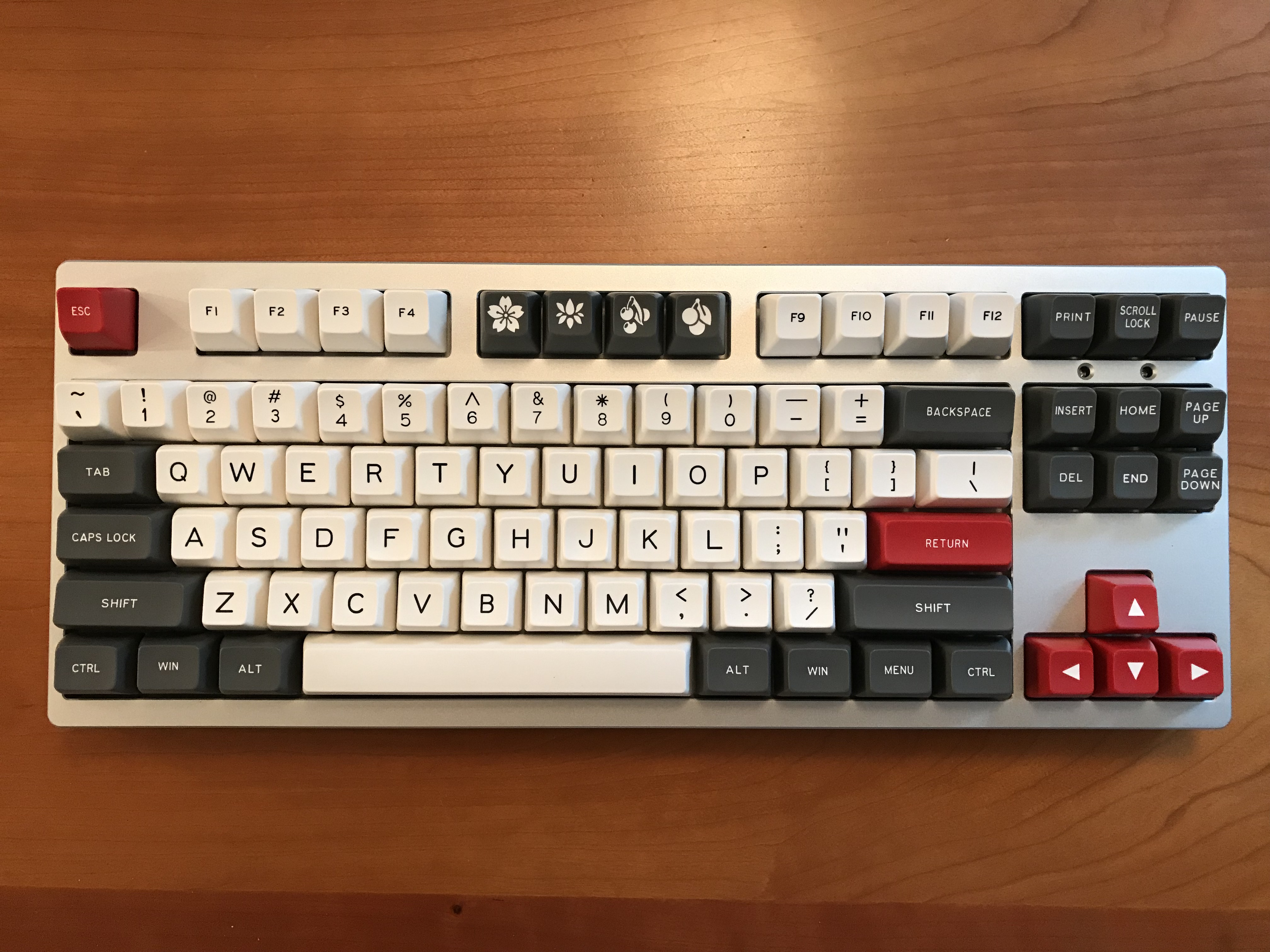
Build #6: Phantom TKL

With five builds complete, and a few more essentially complete except for final decorative touches, I thought it was time to attempt something a bit more challenging, as well as put together what I’ve learned up to this point. Some goals going into the next project:

  • I’ve done a bunch of 60% builds and one ortho, so it seemed like time to try a larger board.
  • All of the PCBs I’ve used have had at least some of the components pre-soldered. How about a bare PCB?
  • Stabilizers remain a sore spot in my builds, particularly with respect to upstroke noise. It’s time to bring out bigger guns.
  • I’ve been avoiding getting into QMK, for no particularly good reason. Time to correct that.
  • Continue exploring Sorbothane treatments for sound dampening.
  • More switch lubing practice. (Wait, I hear you saying, you didn’t tell us about any switch lubing before! That’s true. I write up builds only when they are done - I felt that would be clearer than trying to follow a rolling narrative of all of the simultaneous projects going on. You’ll hear about my conversion to the world of switch lubing in later build logs, even though that experience actually happened prior to this build.)

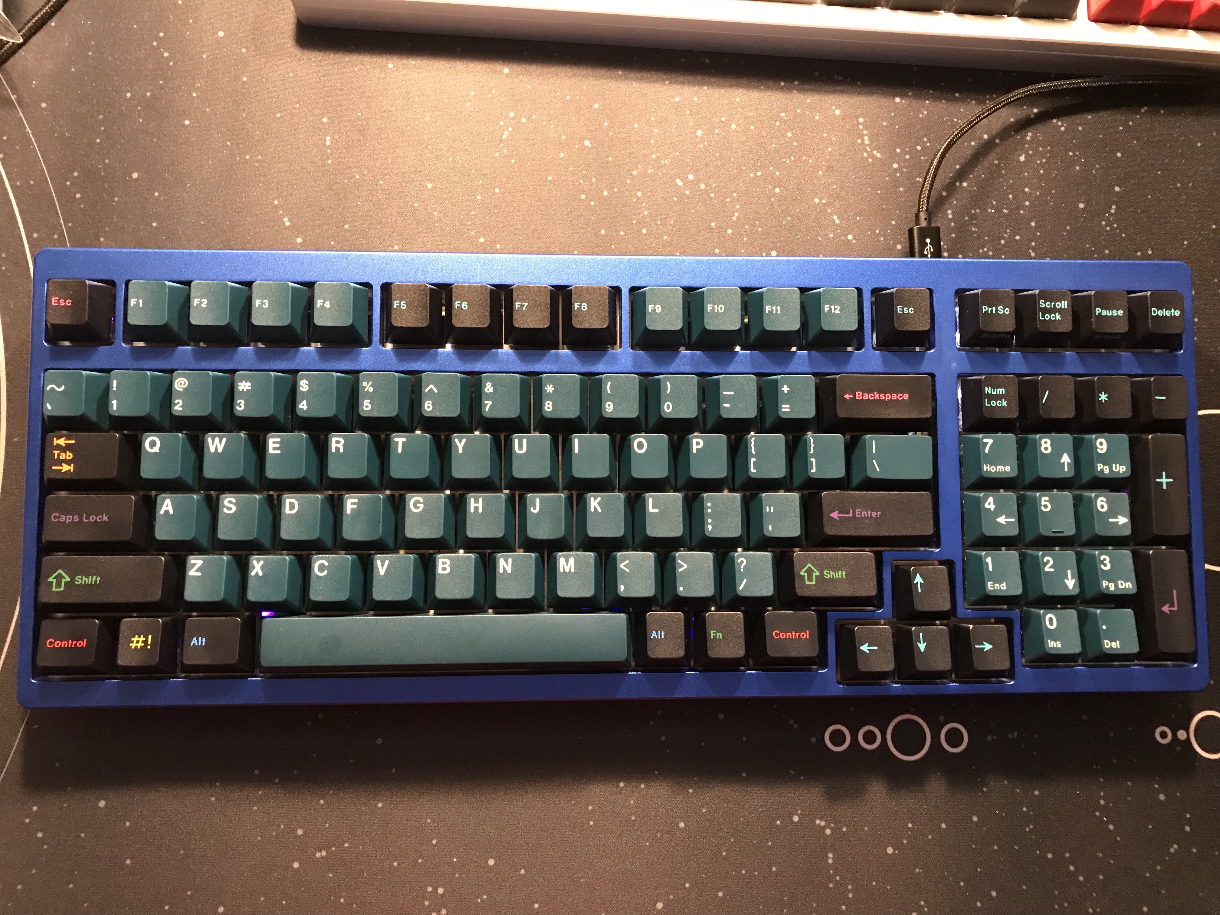
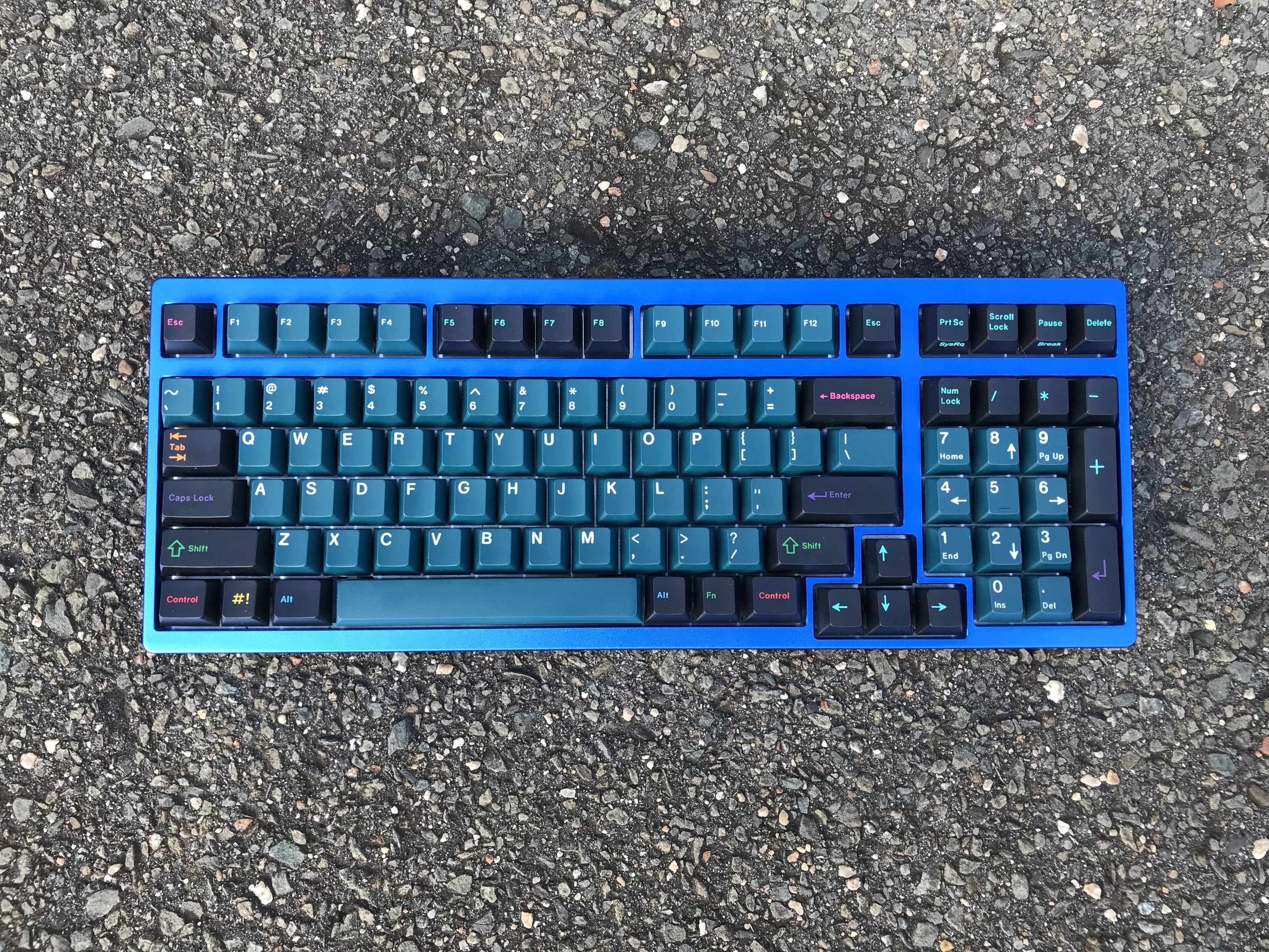
Putting all of that together, I decided to attempt a Phantom TKL build. If my understanding is correct, this is a comparatively old PCB, with origins in a 2012 group buy and a lot of community activity on Phantom builds during that same year, but as of this writing, cases, plates and PCBs remain readily available. That could be good or bad, but since an evening of googling didn’t reveal any obvious non-starters for a Phantom, and there were good online resources documenting gotchas, I decided to go for it.
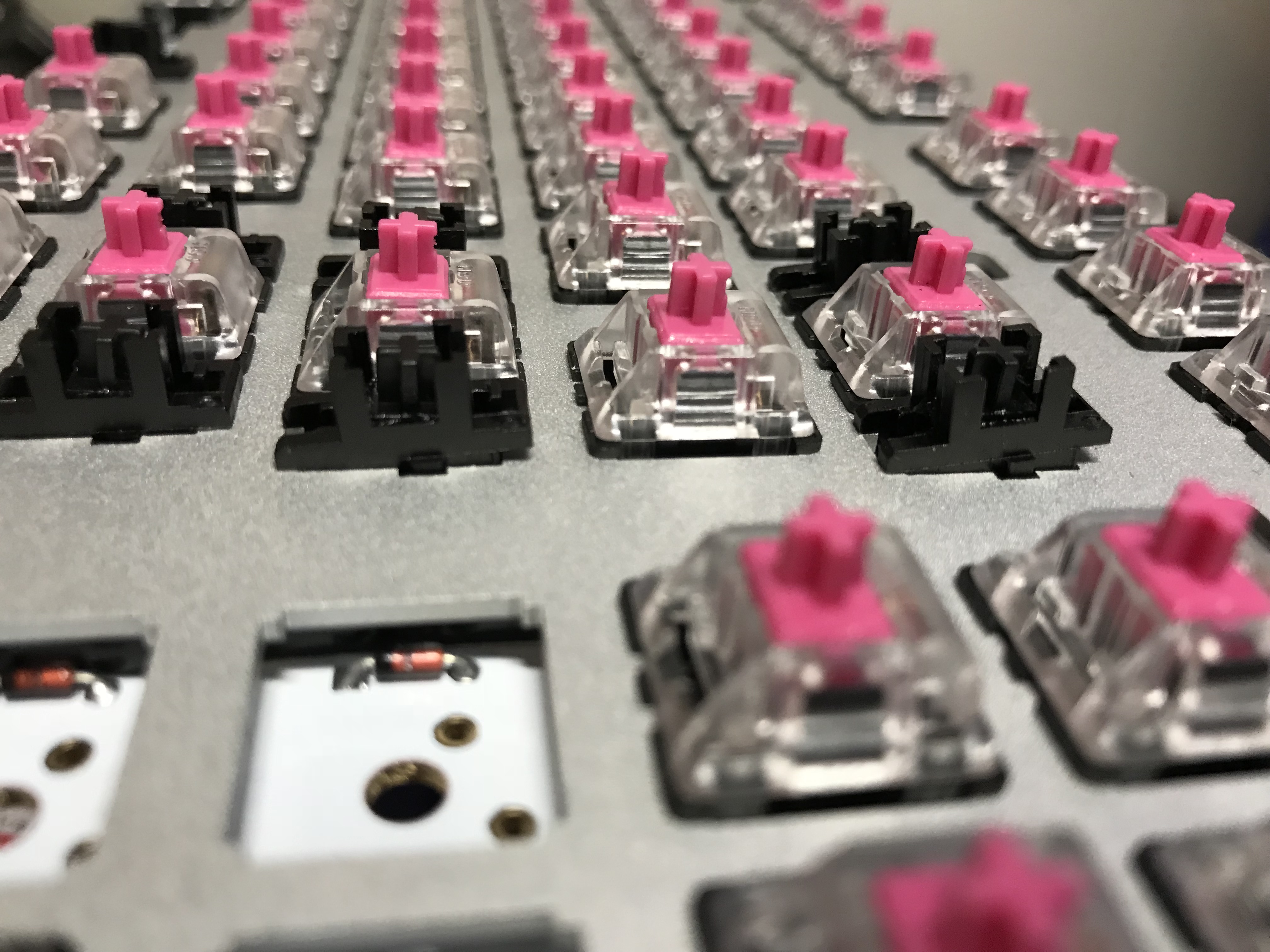
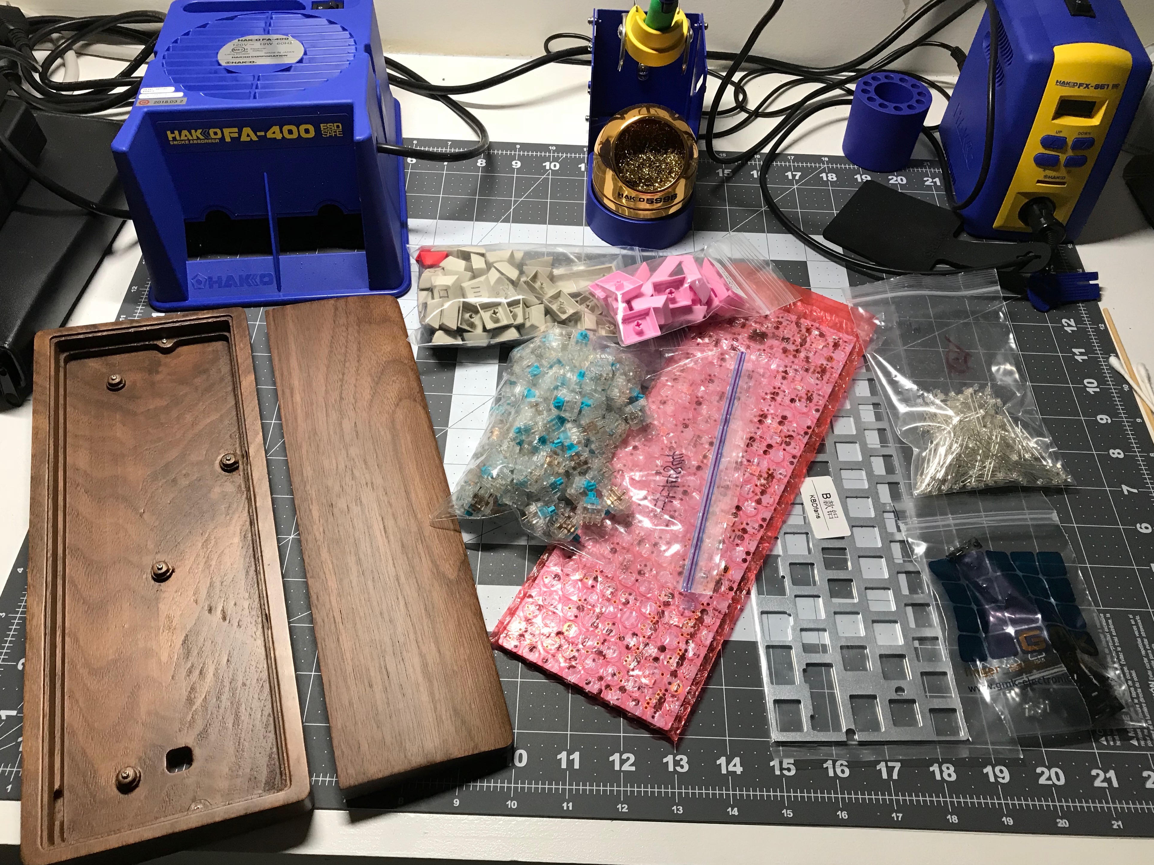
Switch prep

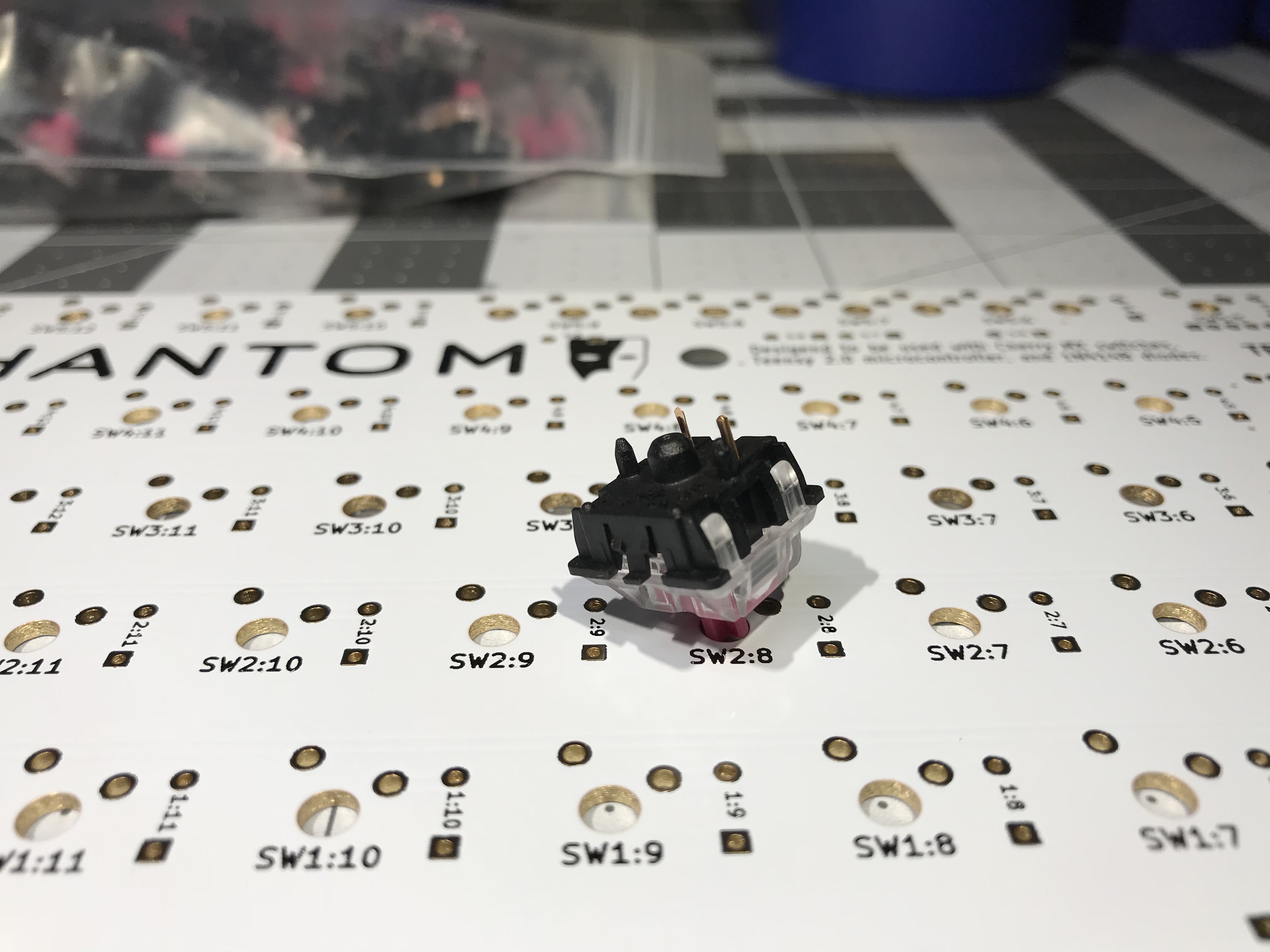
Back before I did my first build, I played with a bunch of switches in a switch tester, where I discovered that I’m a tactile switch guy, and of the switches I had available, Zealios were my fave. However, there were a couple of other switches that felt good on the tester. The MOD-L tactile has a 45g actuation force, which is also roughly the actuation force on a 62g Zealio (recall that Zealios are advertised by bottom-out weighting).
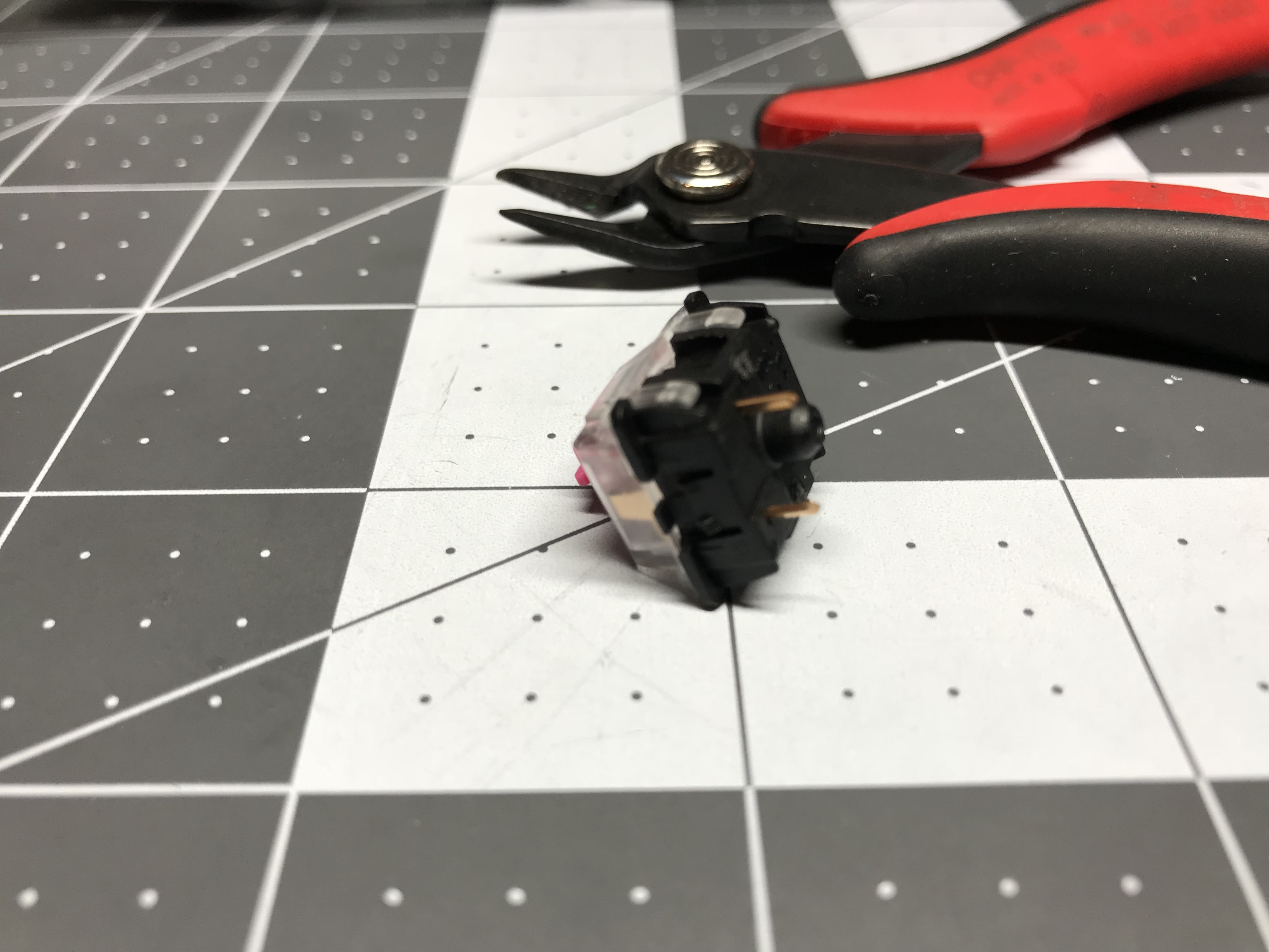
Because the Phantom PCB doesn’t have the holes for the plastic side pins on the MOD-Ls, the first step was to cut those pins off.

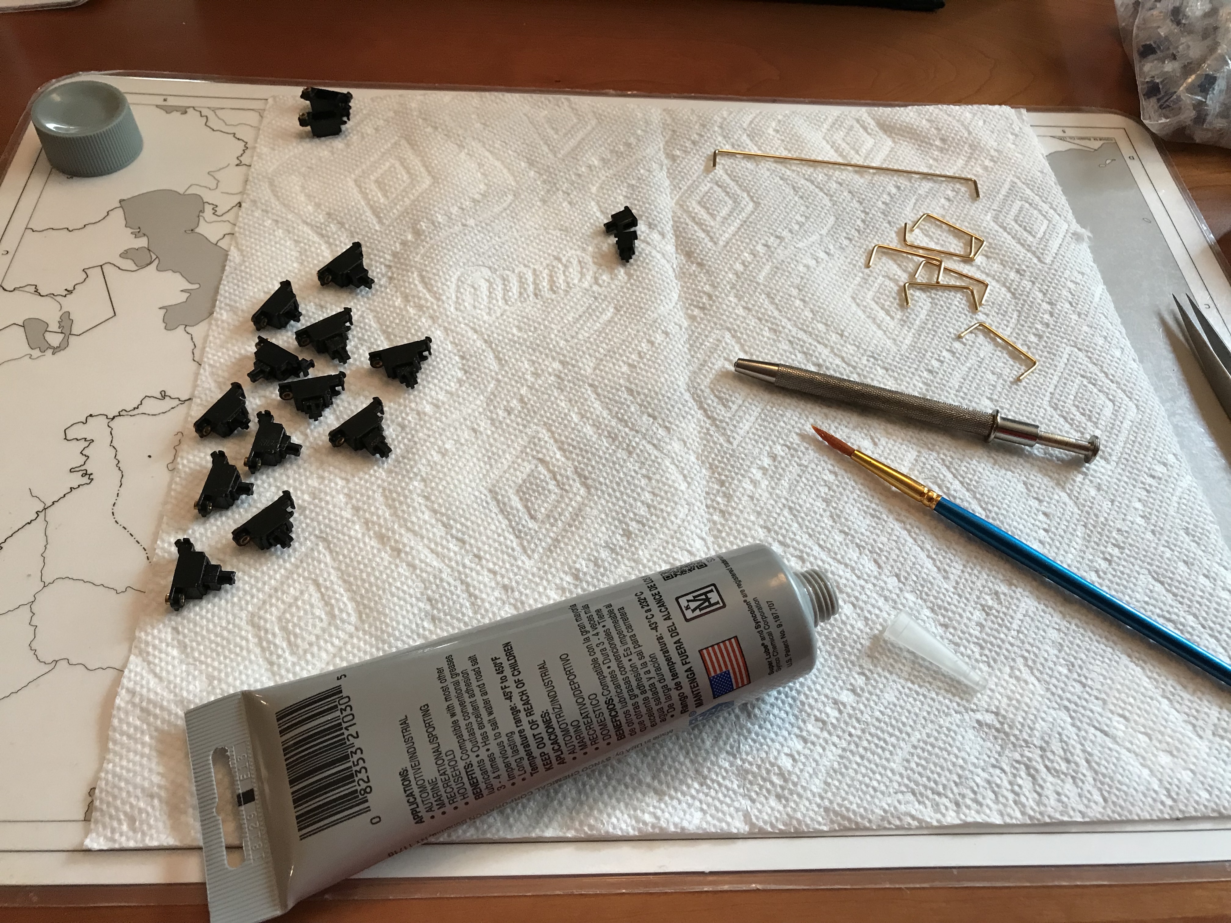
After that, on to switch lubing. 87 MOD-L Tactile switches, meet Tribosys 3204. I like to take my time with lubing, to make sure I’m applying the desired amount of lube in the intended places, but it still takes me longer than I feel it should. I would estimate around four minutes per switch on average, including disassembly, lubing, and reassembly. Midway through the lubing effort, I acquired an acrylic switch lubing plate to organize the lubing process.

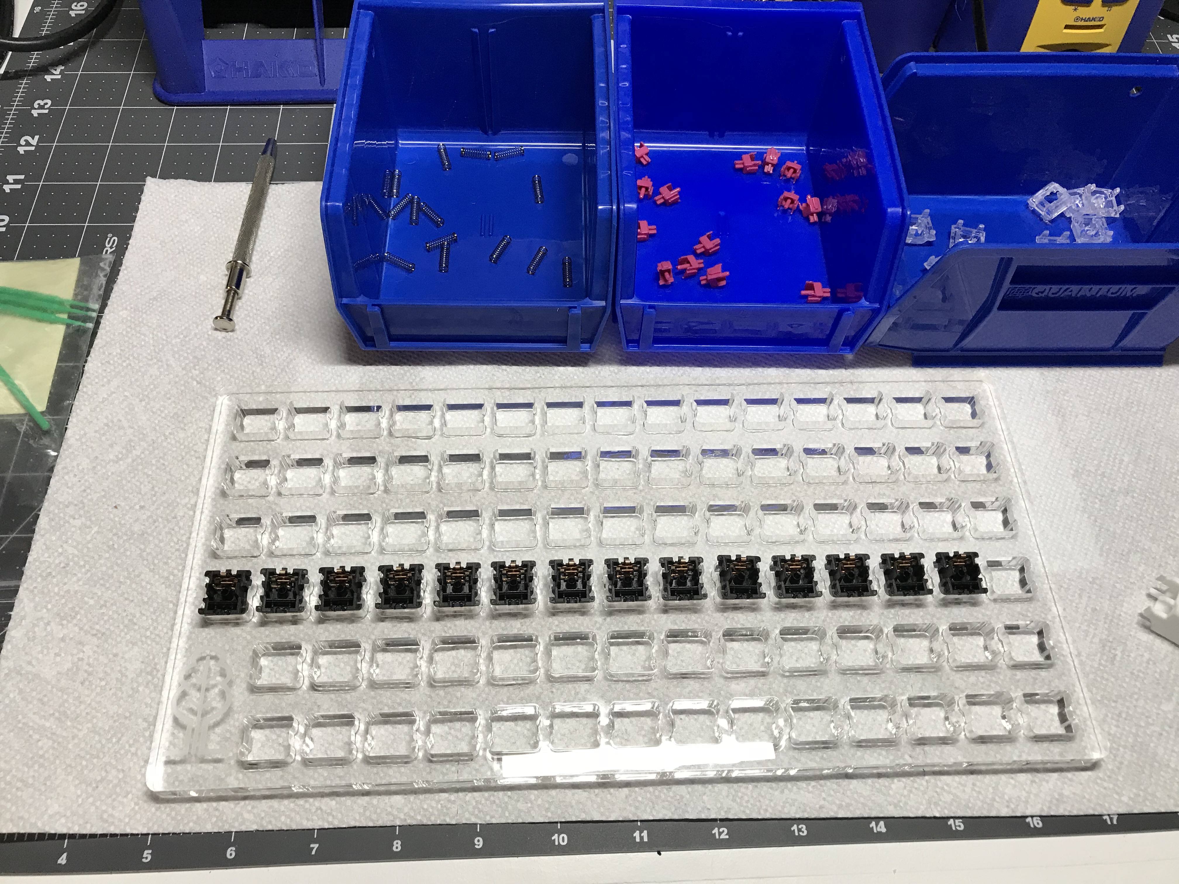
I’d consider one of these switch lubing stations a worthwhile investment if you plan on doing more than one or two boards’ worth of lubing; being able to lube in an assembly line made the process more efficient. I can’t say that it made the process radically more efficient, though. I suppose practice makes perfect.
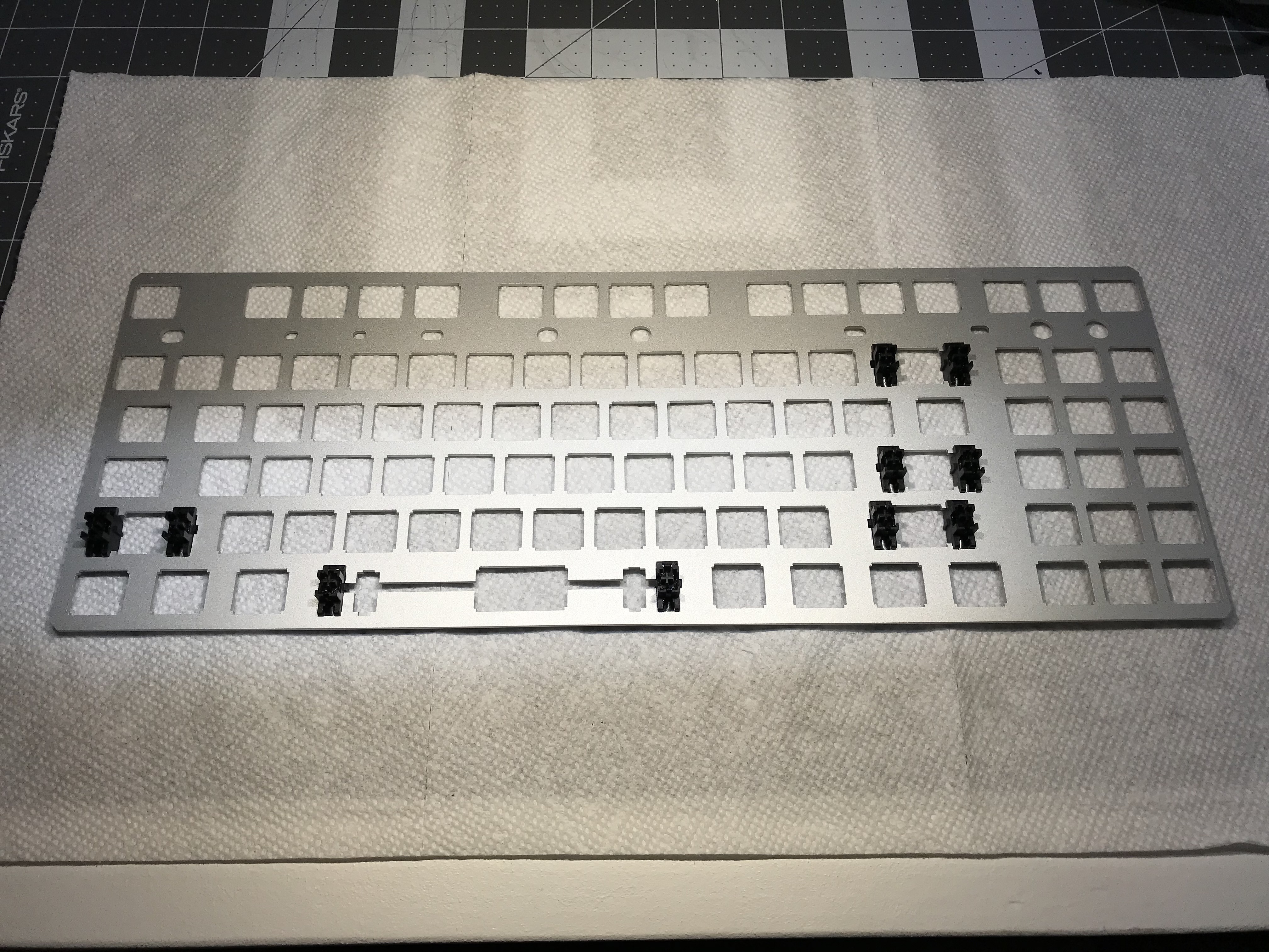
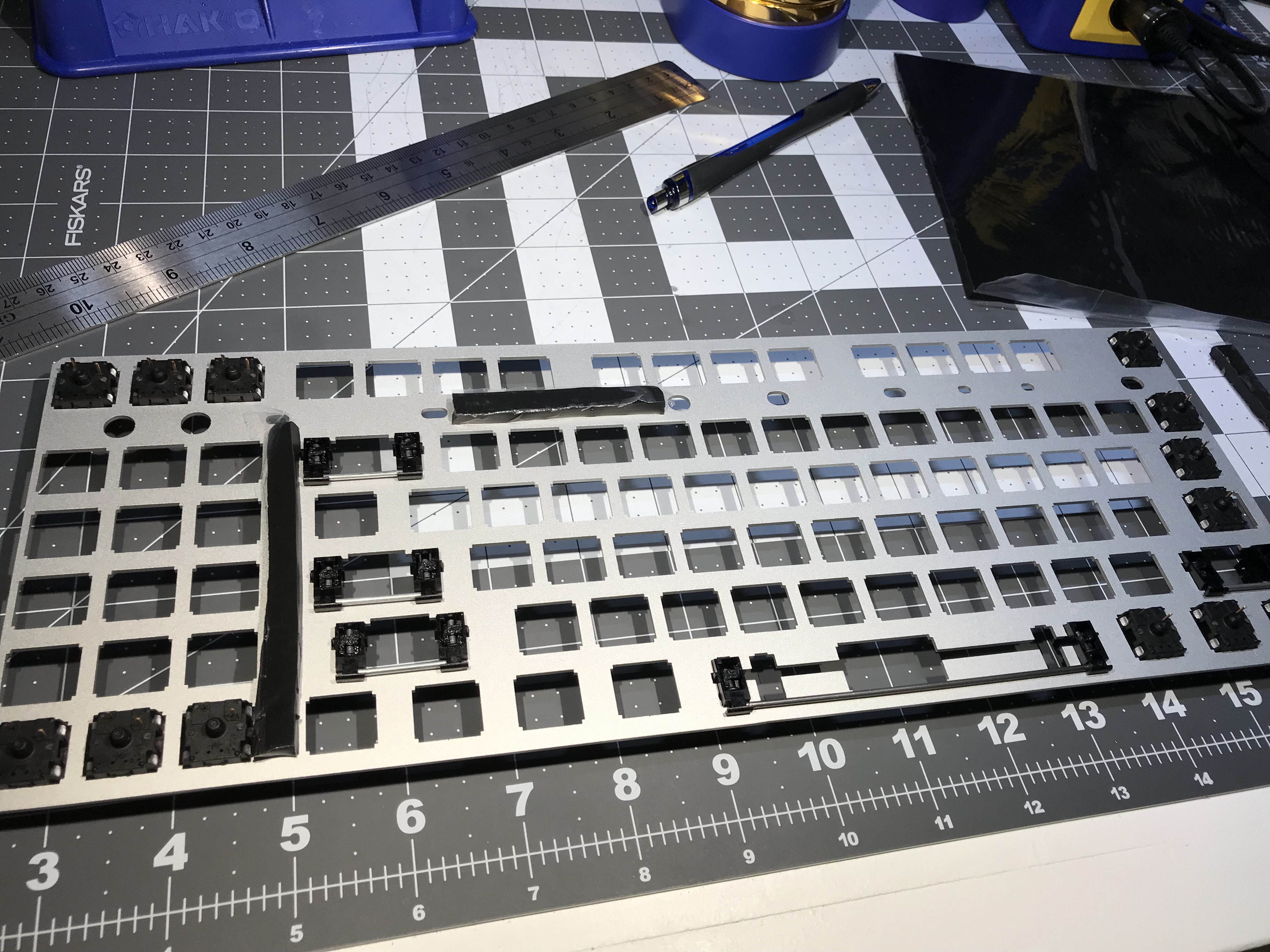
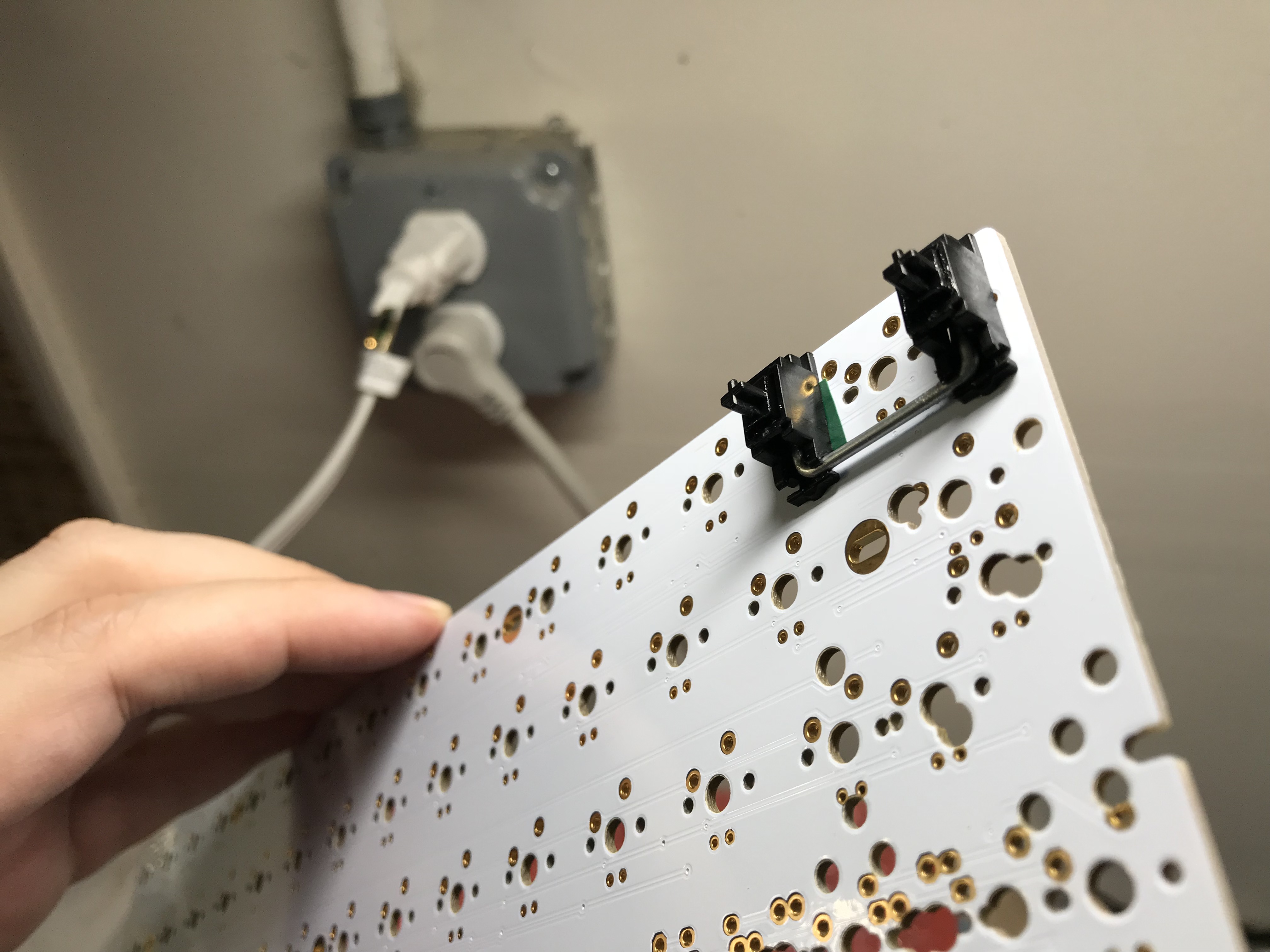
Stabilizer prep

This was my first time working with plate-mount stabilizers, and after a bit of fiddling to figure out how they actually mounted on the plate, ultimately they’re not that different in function or form from PCB-mount stabilizers, so disassembling, lubing, and reassembling goes pretty much the same way as it does for PCB-mount stabs. Up to this point, my standard stabilizer treatment has included clipping, lubing with SuperLube, and doing a “band-aid” mod with silicone pads instead of bandaids, and I could have just done those mods and stopped there.

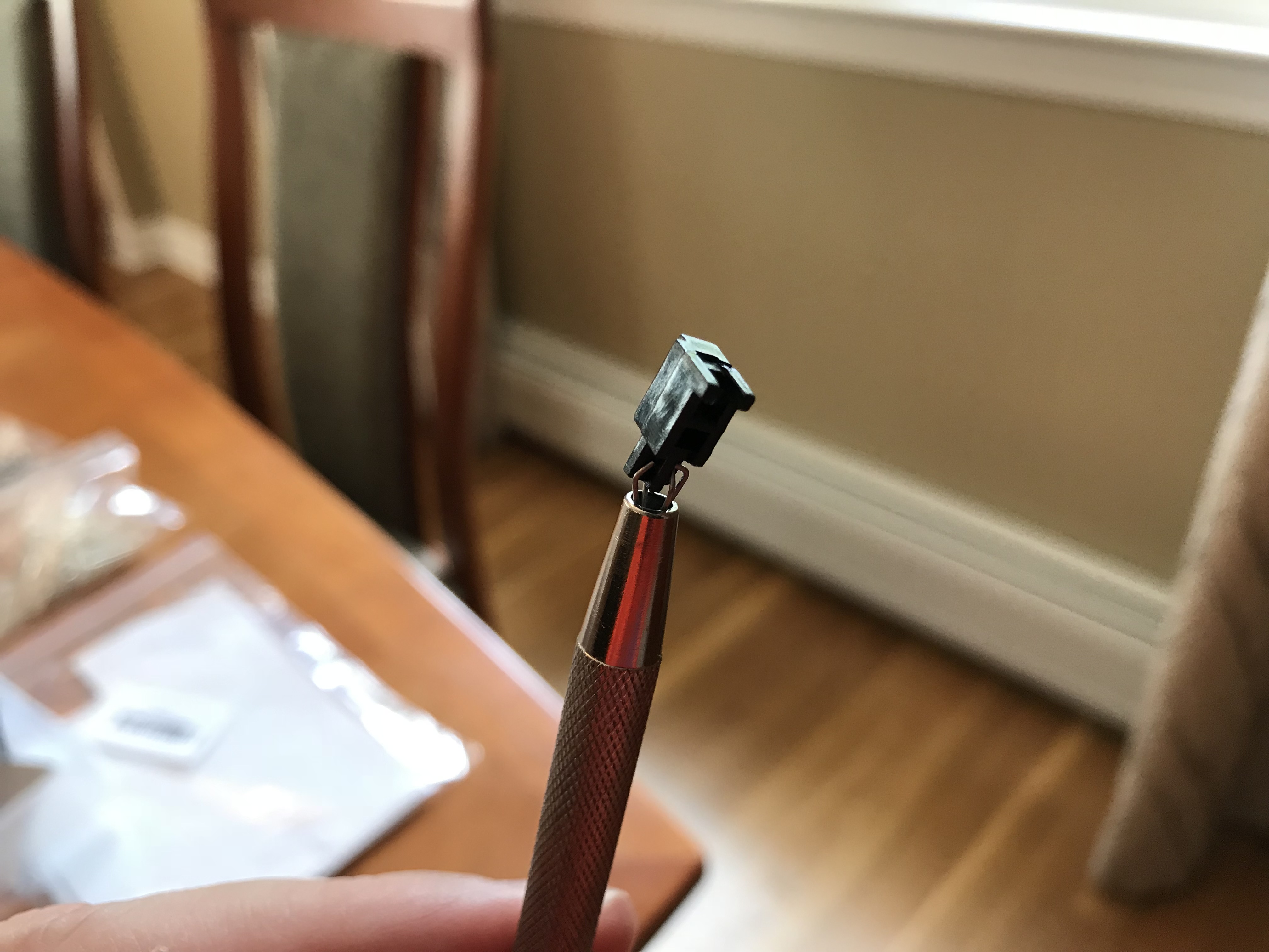
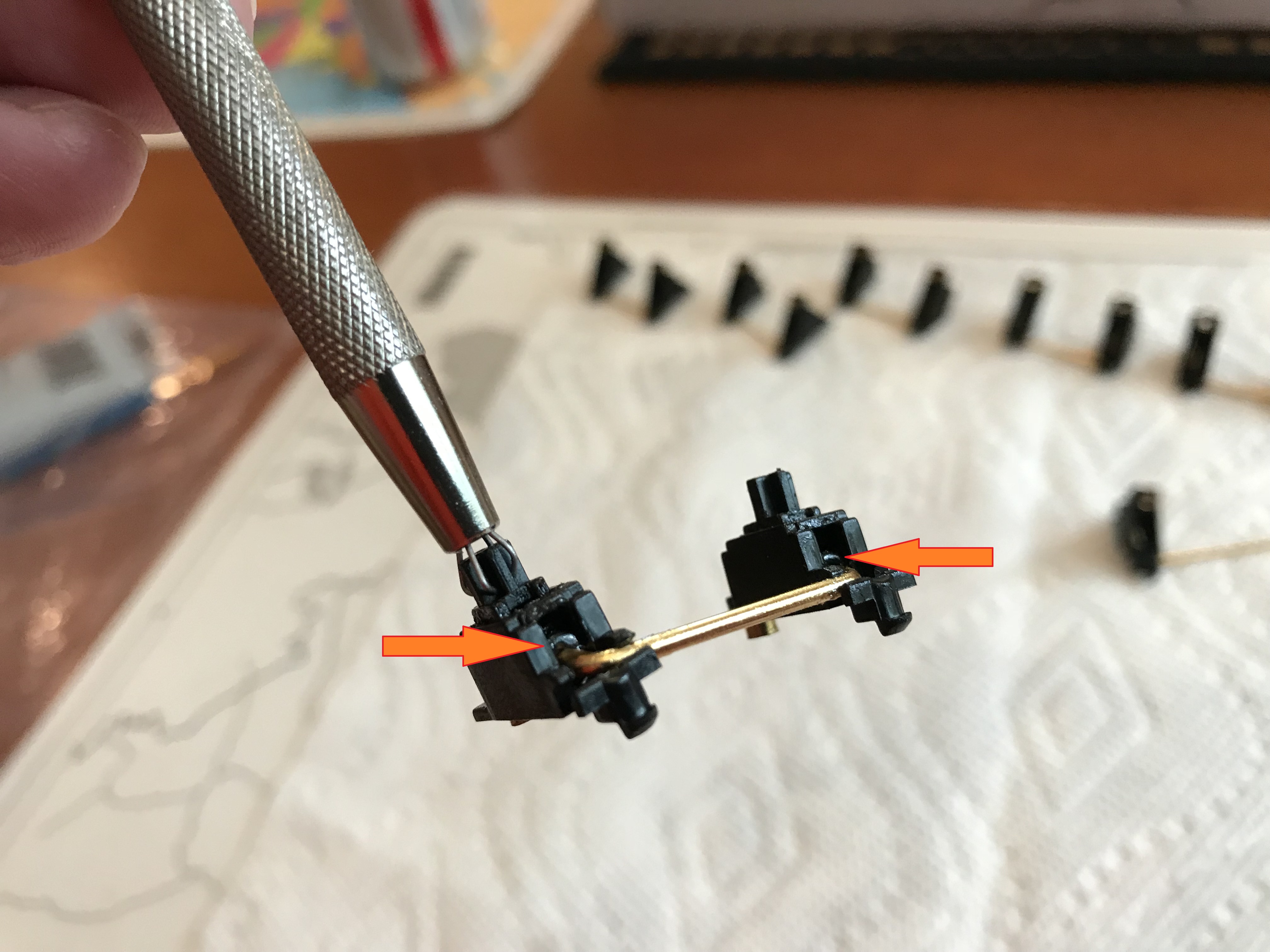
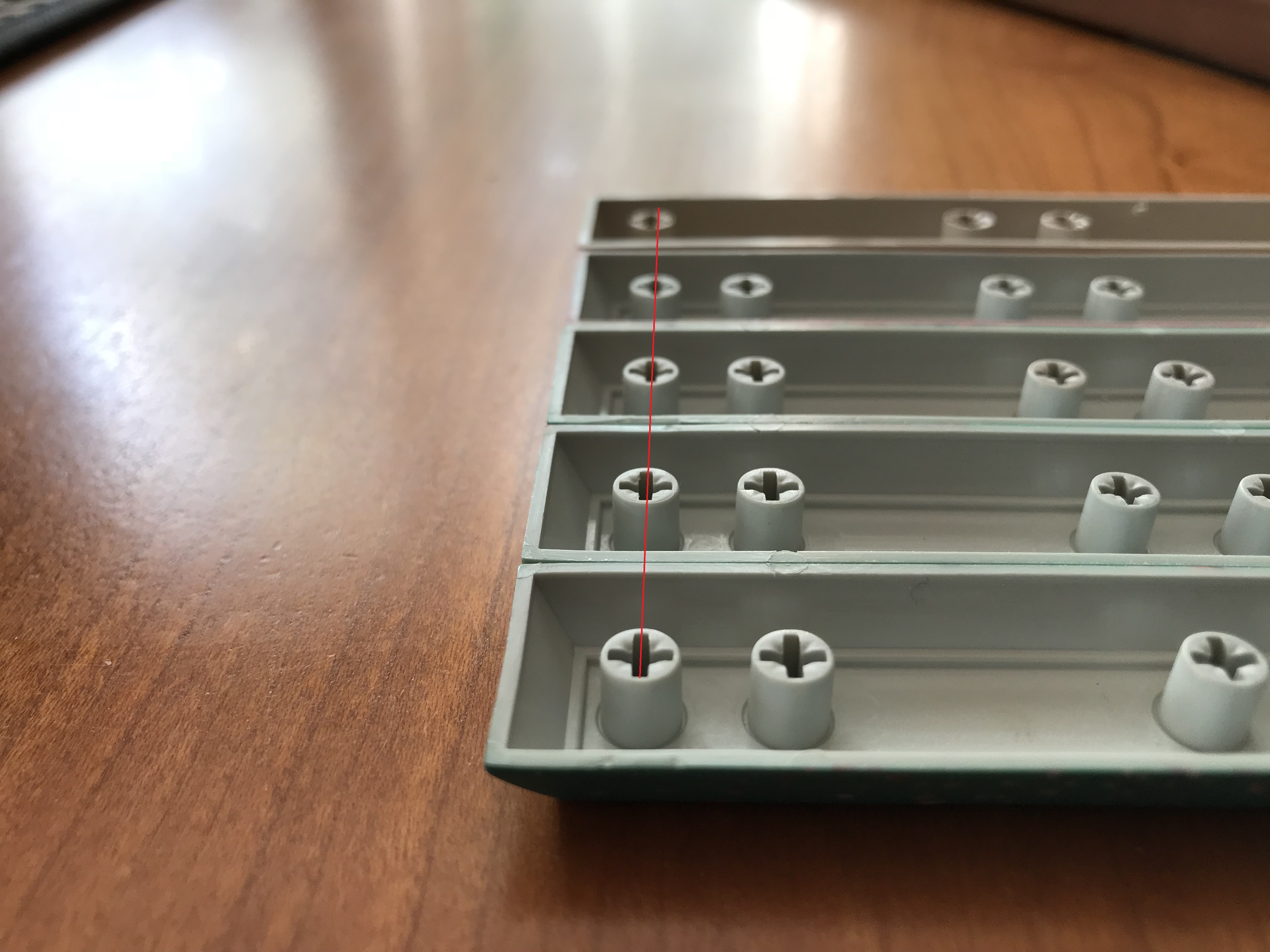
However, I’ve had problems with upstroke stabilizer noise in other builds, and I wanted to directly address that issue in this build. @Walkerstop’s silencing mods - clipping all four slider stems and strategically inserting O-rings into the housings - looked like a novel and interesting approach to the issue. I have little to add to his video illustrating the mods (see the resources section at the end of this build log), other than encouraging you to have a good pair of tweezers on hand if you attempt it. And perhaps a magnifying lens if your eyes are bad like mine; those O-rings, and the space in which they fit, are tiny.

PCB prep

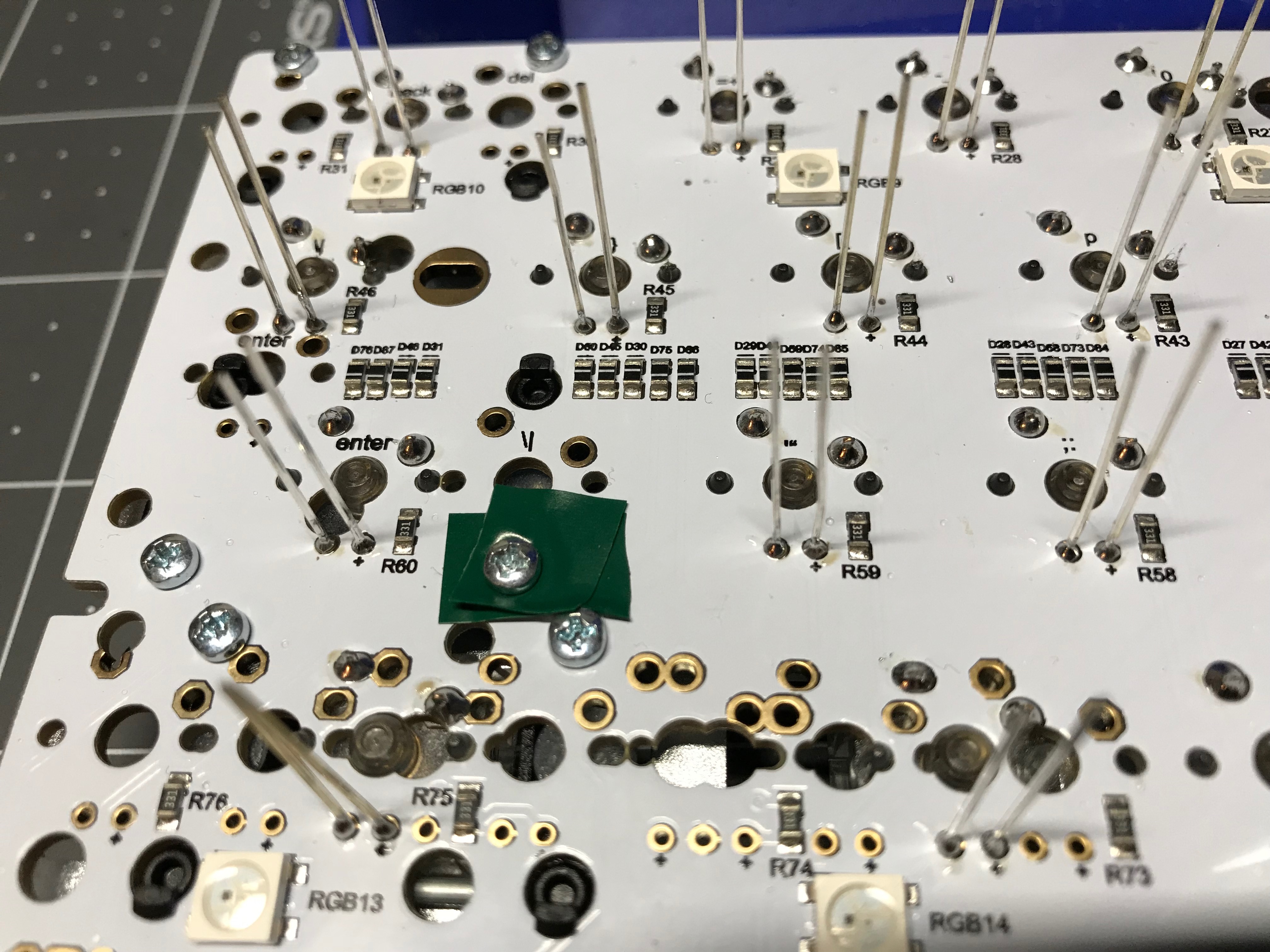
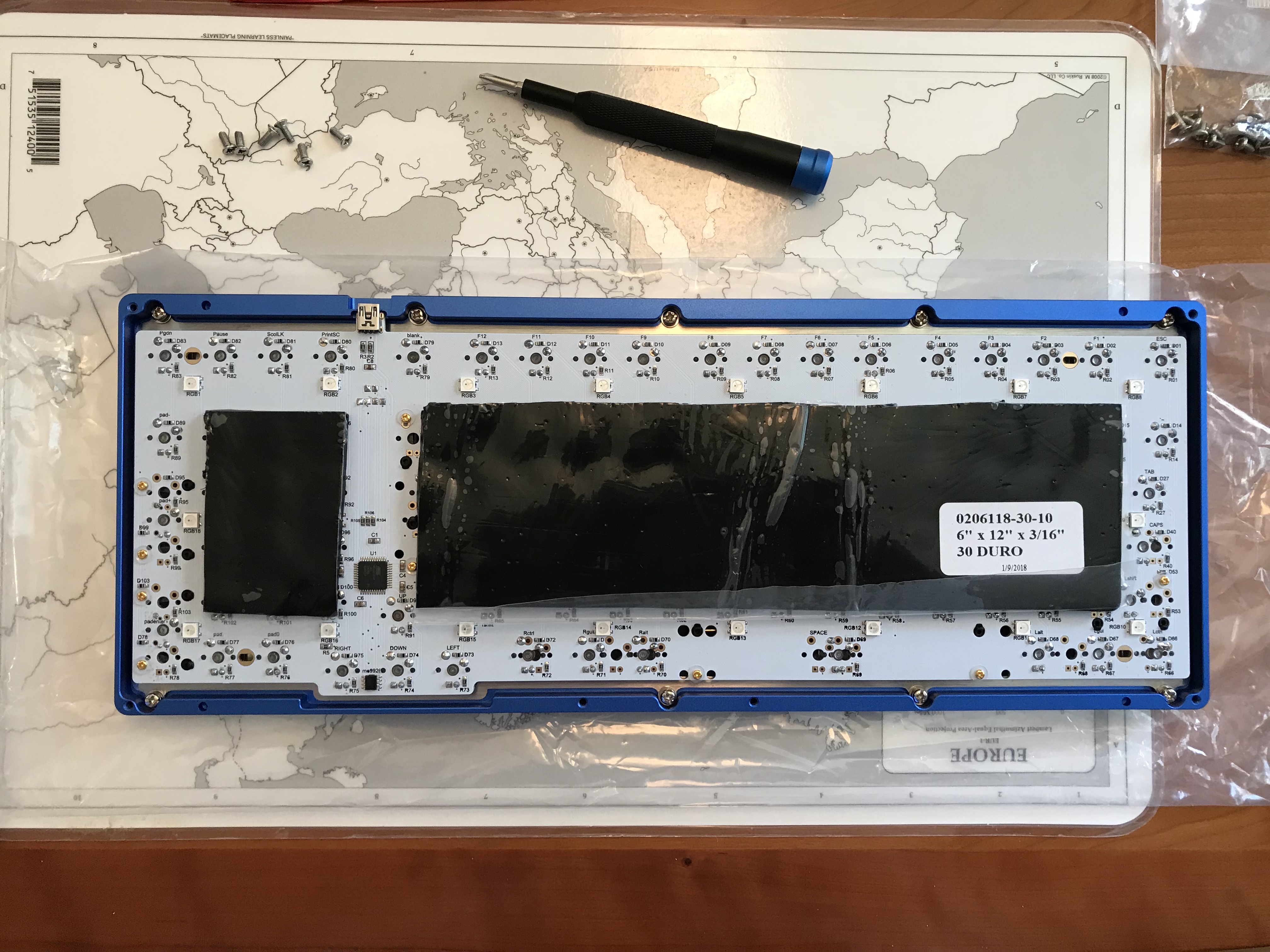
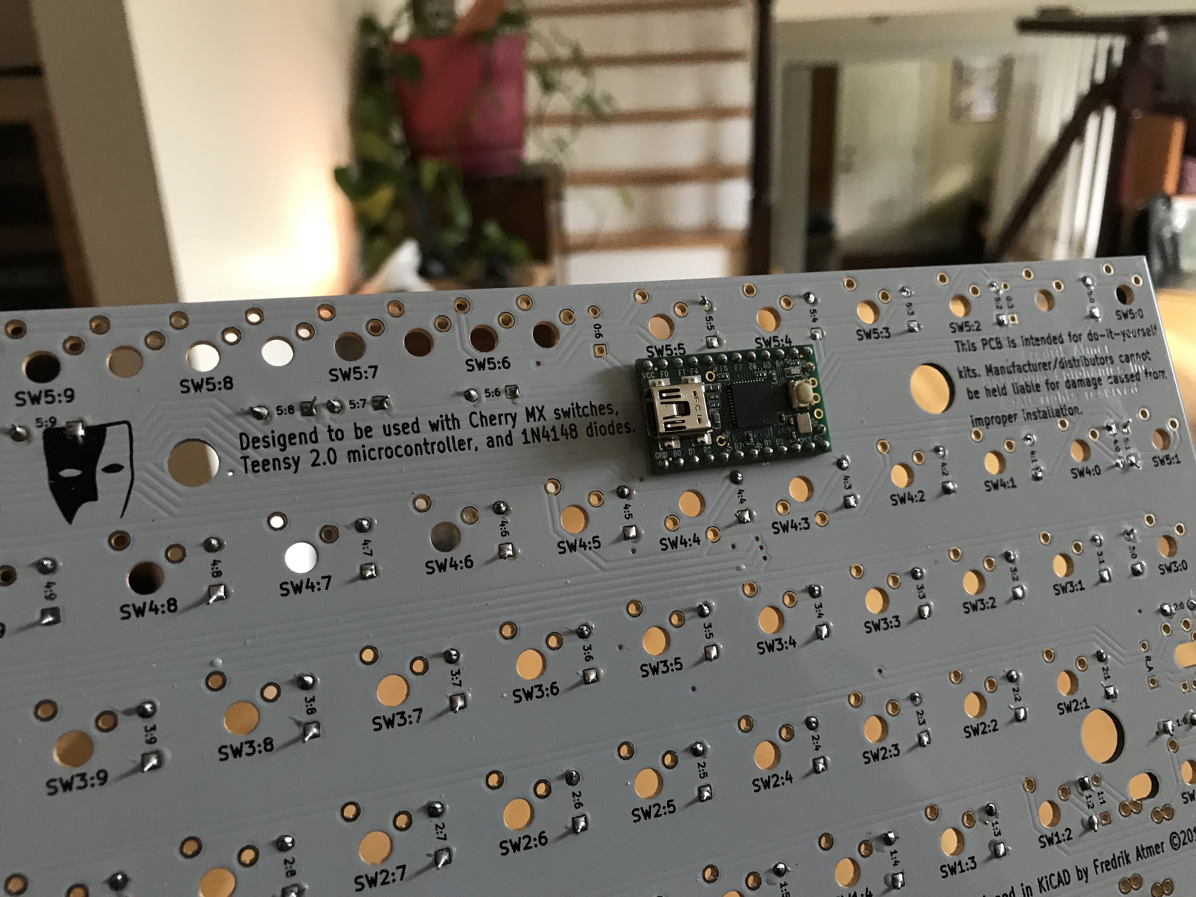
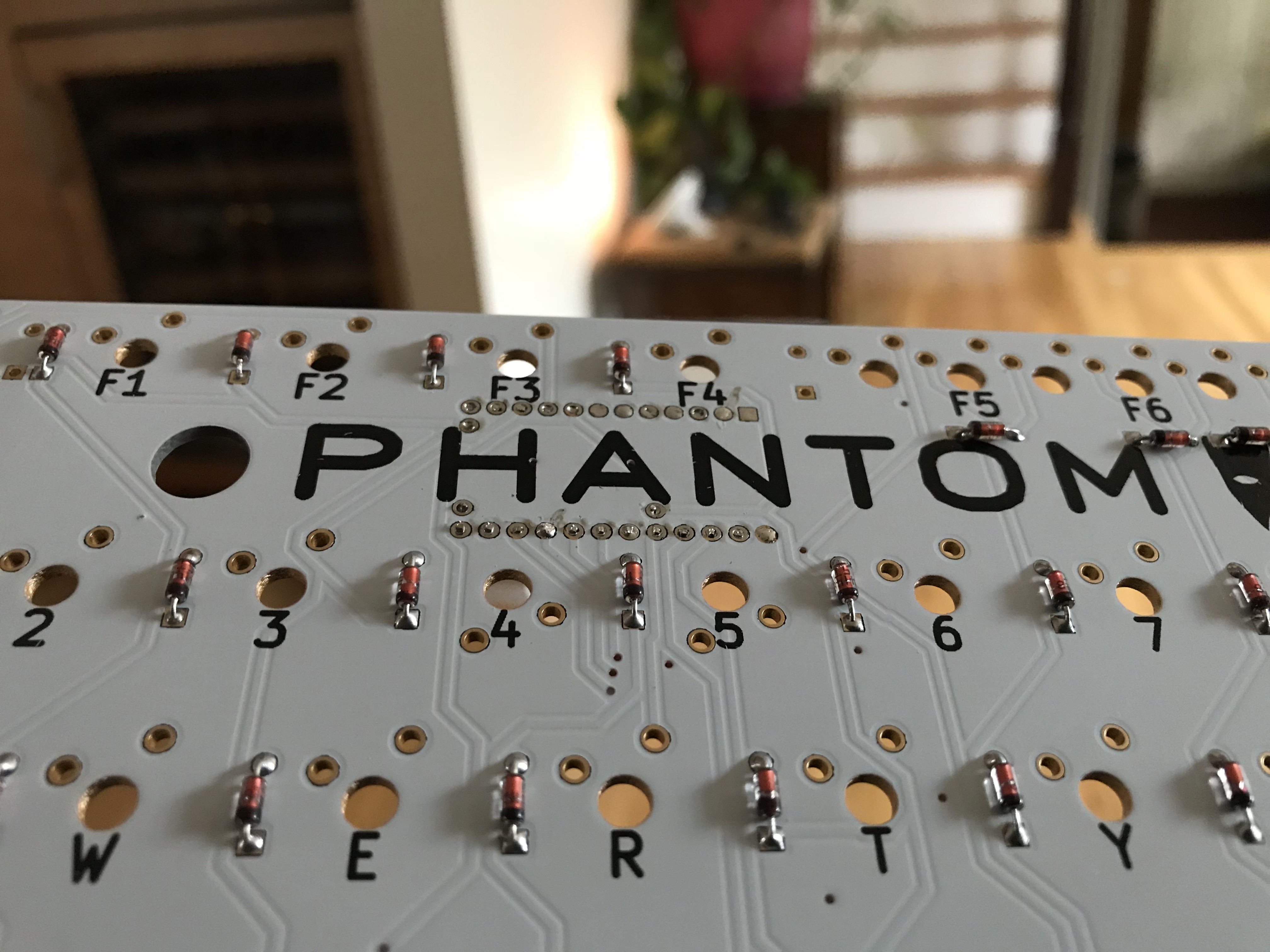
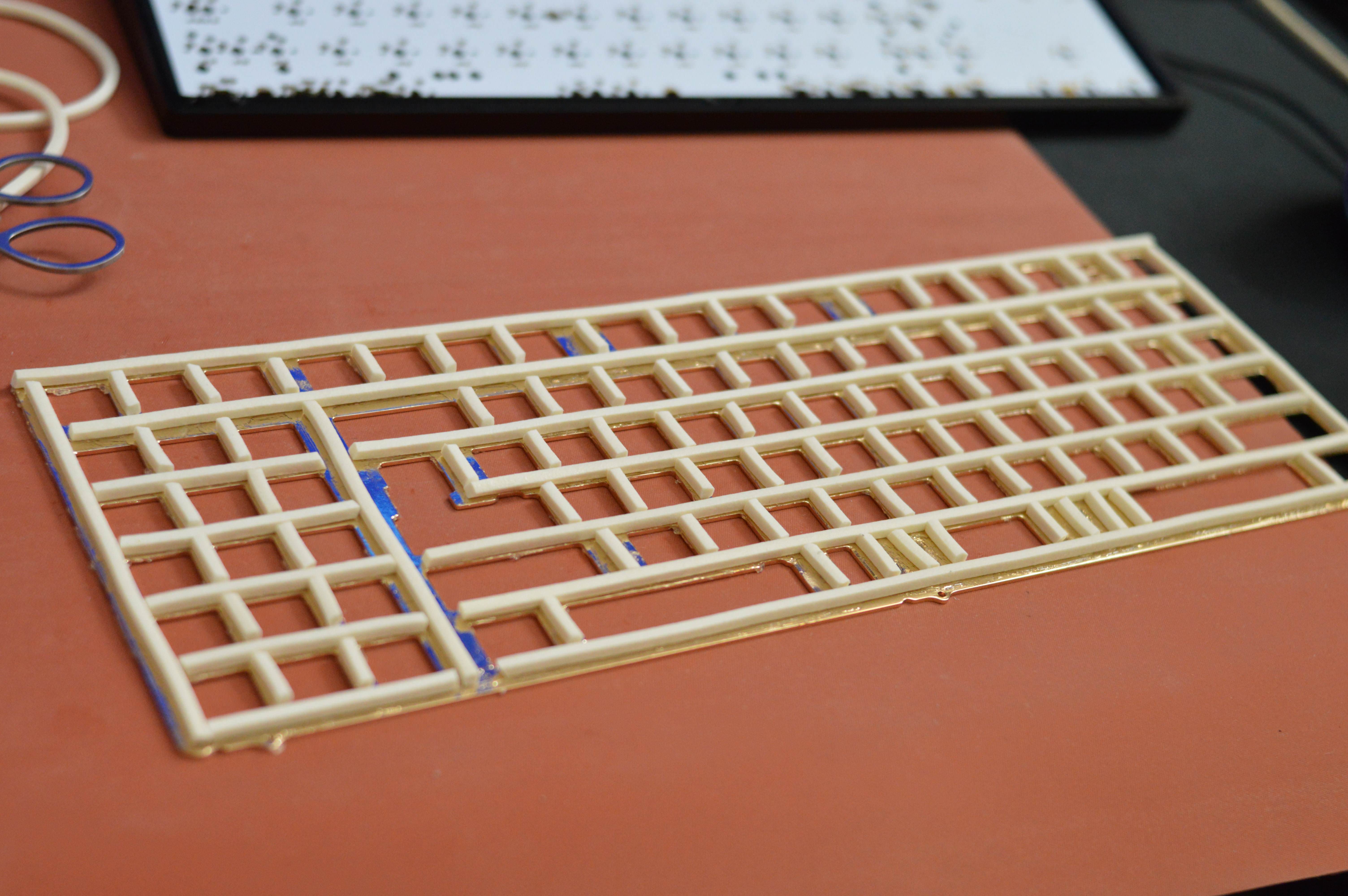
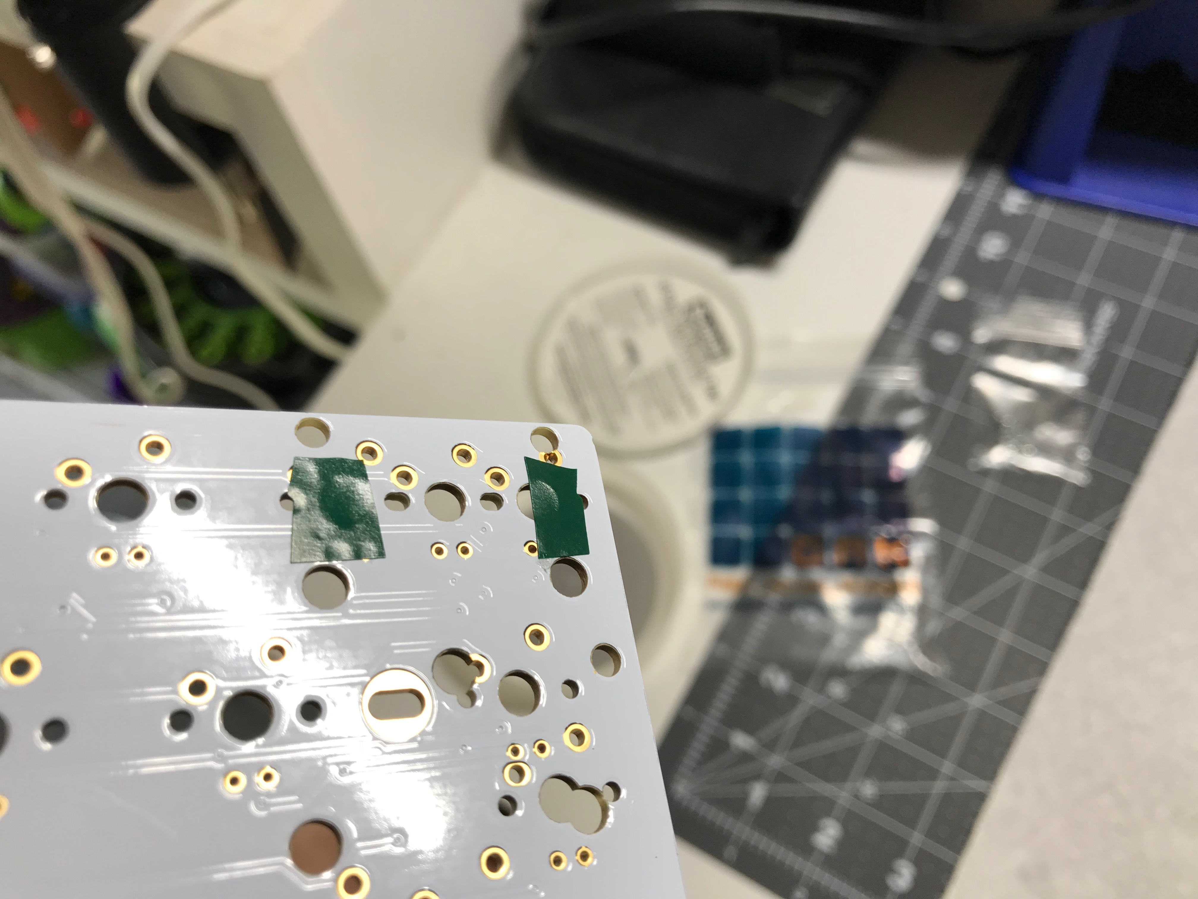
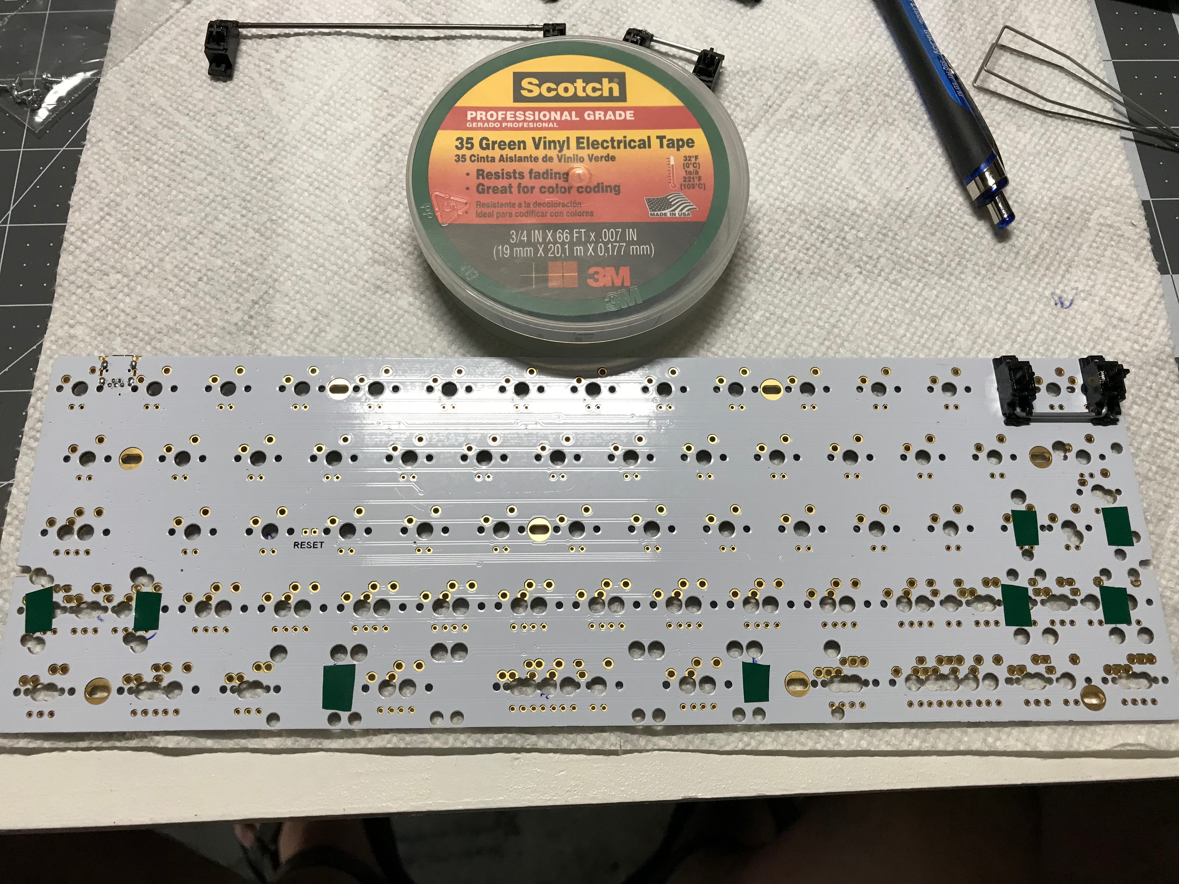
The Phantom PCB does not have pre-soldered diodes, so that’s the first step. We need one diode for each key we want to enable. Before I saw the PCB, I was worried that identifying the holes for the diodes would be difficult, but I needn’t have worried; the diode holes were marked with the same SW<num>:<num> label as the switch holes. So, the only remaining issue with diodes is to be sure they’re soldered in the right direction. Each diode has a black band on one end - that end needs to go through the square diode hole on the Phantom, and the other end through the round hole. Once this was done, I used an old crappy multimeter with a diode testing mode to verify the correct orientation for each diode. Note that switches SW4:3 and SW4:4 are upside down, so you’ll have to switch the multimeter probes for these two switches.

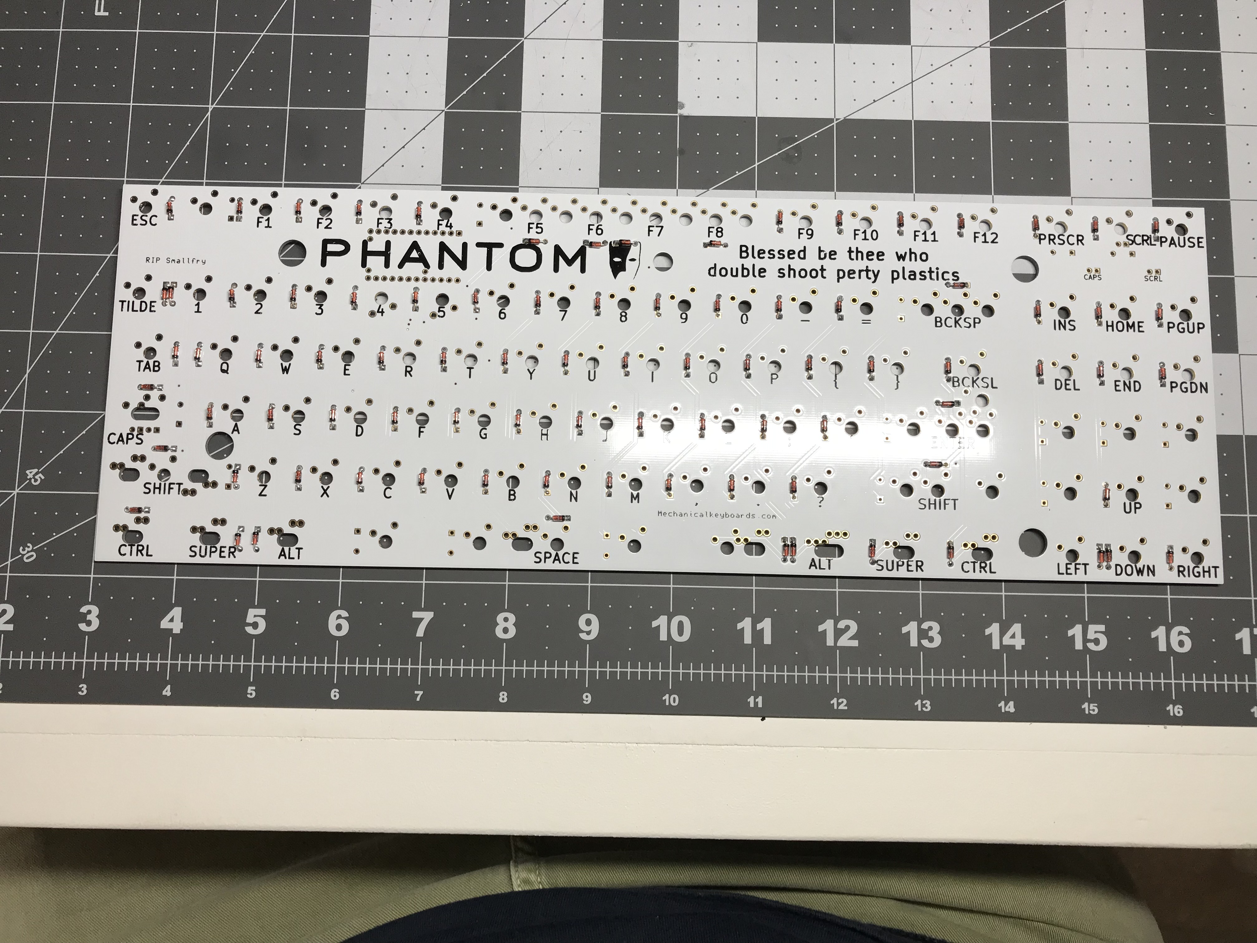
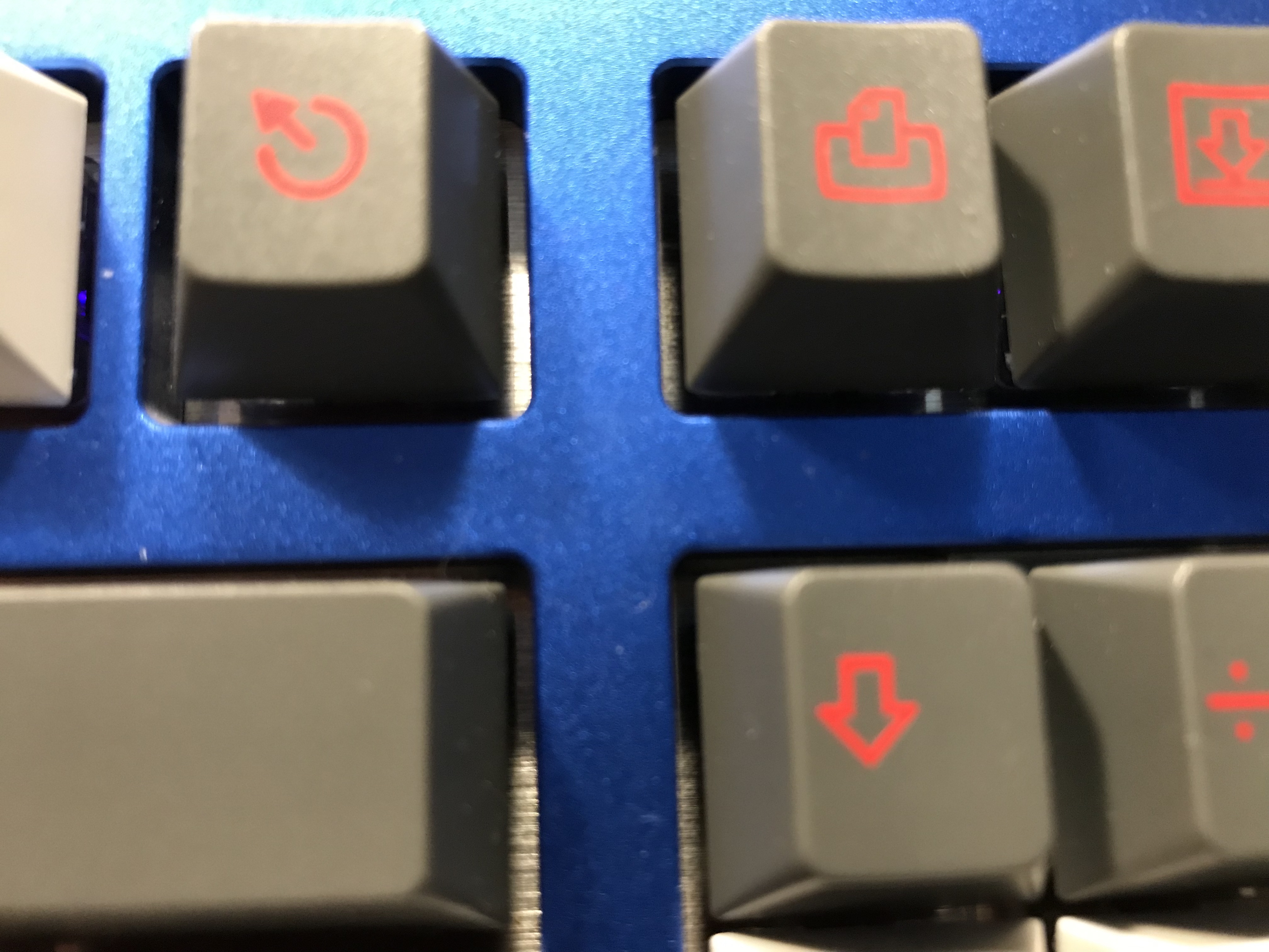
Because I’m me, I added diodes to the five “extra” keys the Phantom offers, between the arrow cluster and the
2x3 insert cluster. I thought enabling these keys might be an interesting test case for my first foray into QMK.
Note that the photo above shows the PCB before those last five diodes were soldered into place.

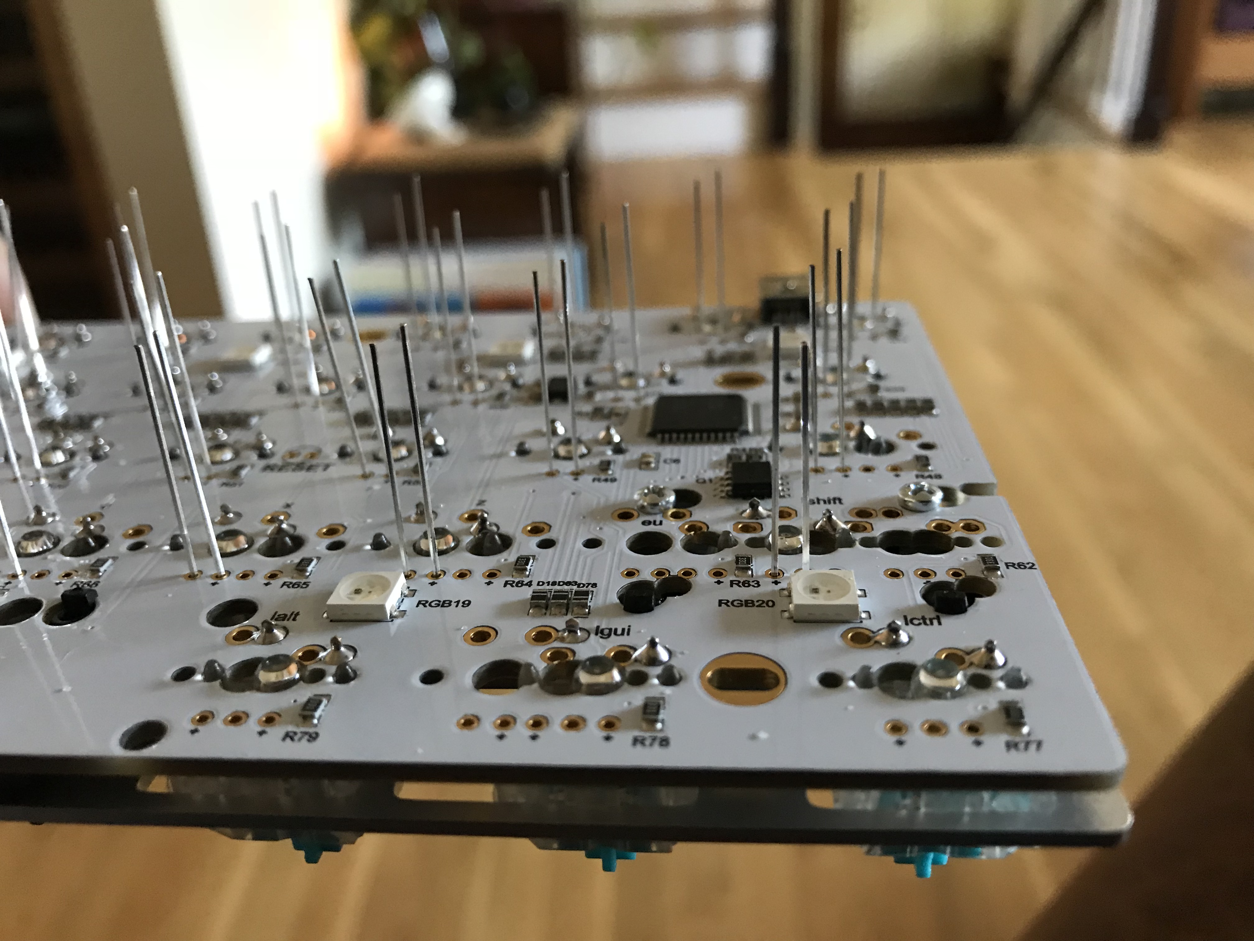
Next up: soldering the Teensy board to the Phantom PCB. Before doing anything else, I plugged the Teensy into the PC to verify that a light on the Teensy was blinking on and off for a 1 second cycle, indicating that the board is functional. Next, I had to remove the spacers from the Teensy board. I ended up doing that with a very small flathead screwdriver to gently pry the spacers away from the board, using the screwdriver at several different locations on the spacer to distribute the force evenly. Next, I had to solder pins onto the Teensy board at locations D4, D5, and E6, and as recommended, leads clipped from diodes serve adequately as pins for the Teensy. Soldering these pins onto the Teensy would be a three-handed job, unless you still have the protective foam that came with the Teensy, in which case you can seat the Teensy and the pins in the foam to hold everything stable while you solder the pins. This worked well. It’s worth seating the Teensy on the board at this point, to be sure all of the pins are going through the holes.

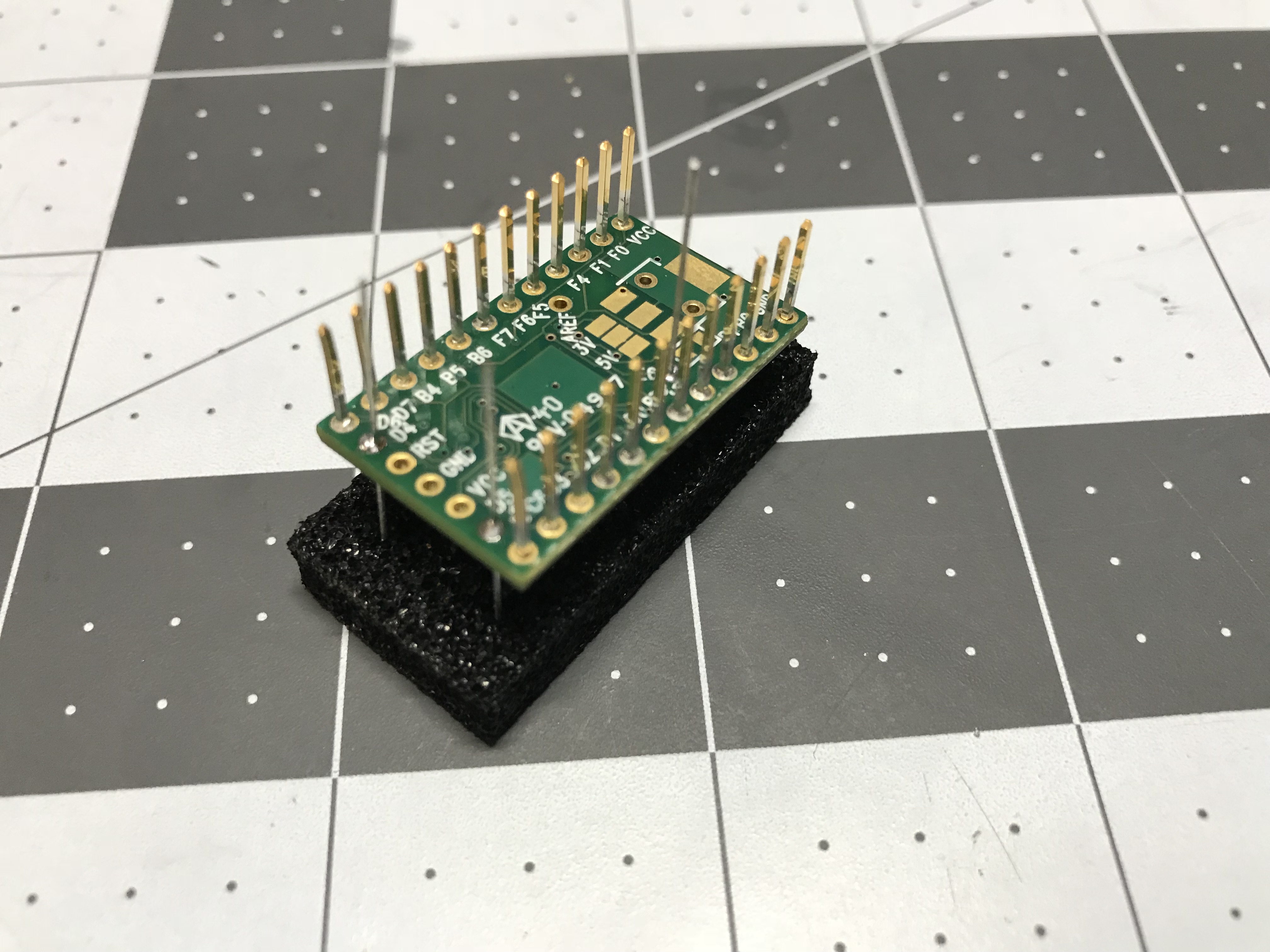
Now, before soldering, with the Teensy seated, you need to clip all of the pins so that they are flush with the Phantom PCB surface, so that you can get the solder joints as flat as possible. This is necessary because the switches for four keys are seated in close proximity to the Teensy, and if these solder joints are not flush with the board, they have the potential to push the switches for those four keys out of alignment. Flush cutters are essential for this task.

With all of the Teensy pins flush cut, it remained to solder the Teensy onto the Phantom PCB. My solder joints weren’t perfectly flat, but a quick switch mounting test looked OK, so I decided to proceed.

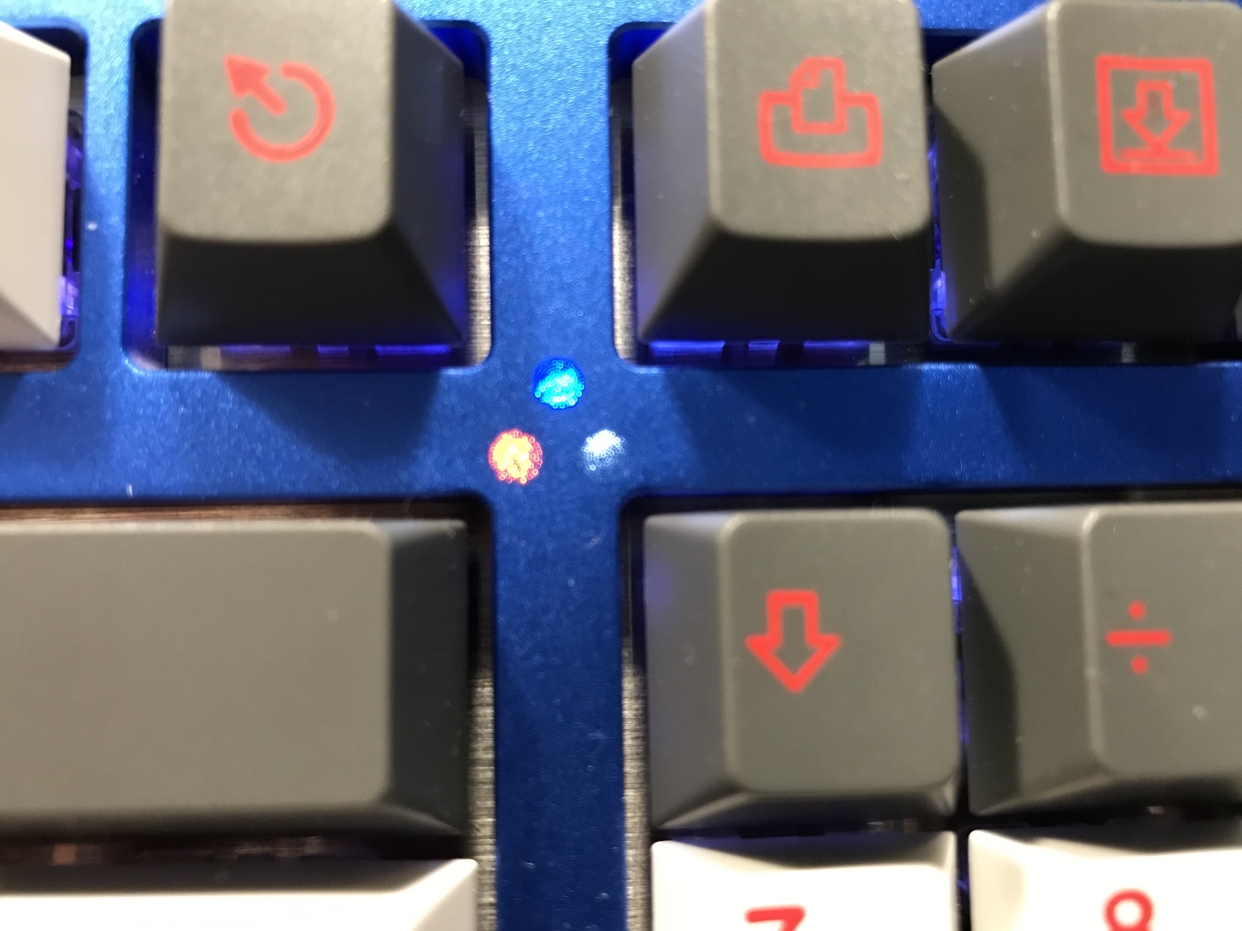
Finally, the last step for PCB prep involved soldering resistors and LEDs for the Caps Lock and Scroll Lock keys. The case for this build was a Filco-style case, with light cutouts below the scroll lock key. The LEDs I had were rated at 3V 20mA, so (5V-3V)/20mA implied a 100-ohm resistor rating, but they were also high-brightness LEDs. I was worried that at max current, this type of LED would be far too bright for use as indicator lights. To guard against that, I used a couple of 220-ohm resistors. Aside from that, the only other issue is that the LEDs needed to be mounted on spacers, but that’s not a big deal.

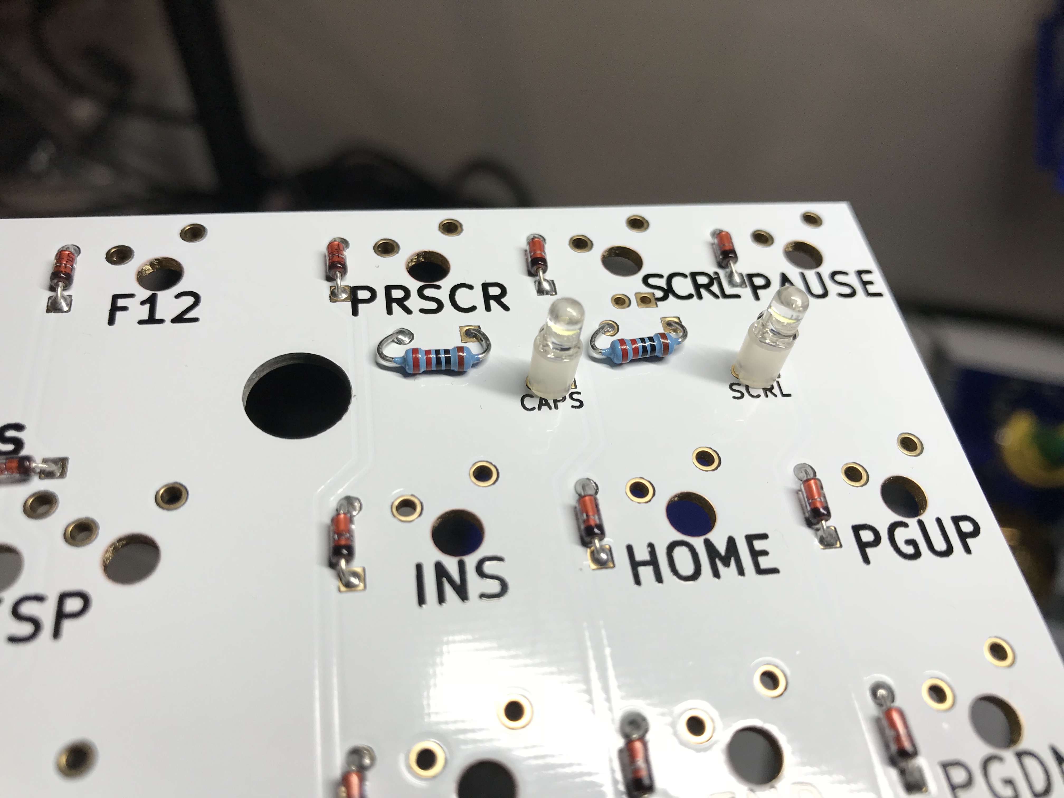
After soldering, a quick tweezer test confirmed that the indicator lights were working, albeit still quite bright.

QMK

The QMK documentation is pretty reasonable, and I didn’t run into any trouble installing MSYS2 on Windows or using git to get the latest QMK code. Remember those extra five diodes I added to the PCB? Those additions meant I had to create a new layout (description of the physical key layout) for this 92-key Phantom, but that turned out to only involve editing a couple of files (these changes are now in the qmk_firmware repo on GitHub). After doing that, the process of compiling a default keymap is just a matter of running the util/new_keymap script, using make to build the firmware, and then flashing the resulting hex file to the Teensy with QMK Toolbox.

It took me a while to work through all of this the first time, but there weren’t really any problems. It was quite satisfying to flash the Teensy, fire up a keyboard tester, grab a pair of tweezers to test switch points, and find that I had a fully functional PCB and controller. Sweetness!

I’m in the process of going deeper with QMK, and I’m working on a unified keymap for all of my boards using the userspace support - but we’ll save that discussion for another time. In retrospect, I should have started poking around QMK much sooner. There is a lot of great stuff there, and it’s worth looking at all of the keymaps and features other people have contributed.

PCB/plate dampening

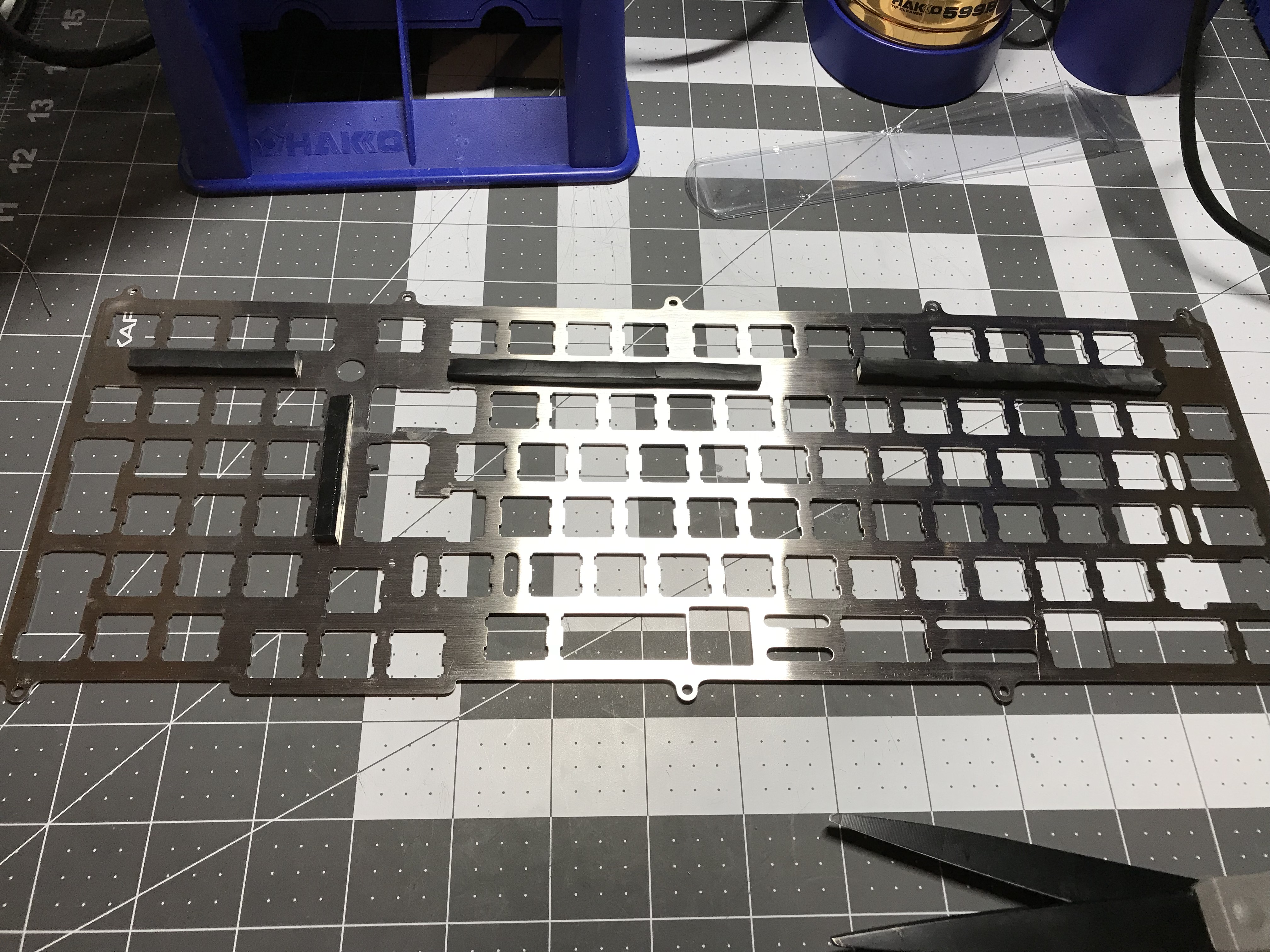
Bring out your Sorbothane! Having tried 0.25" thick sheets as part of a PCB/Sorbo/plate sandwich, and finding that just too thick, I gave it another go with a 0.188" sheet, cutting in into 1/4" or 1/8" wide strips and laying these pieces on the wider parts of the bottom of the plate.

Unfortunately, this was also too thick; I wasn’t comfortable with the pressure that was going to be necessary to get the sandwich soldered together. My janky solution was to use scissors to shave roughly a fifth of each strip away. This was anything but a precision job, but close enough to get some strips that were making contact with both the PCB and the plate in a more gentle fashion.

This really made a difference - before the Sorbo sandwich, I could hold the plate/PCB assembly and get noticeable plate ping by just tapping the plate with my knuckle. Afterwards, a nice dull bass thunk.

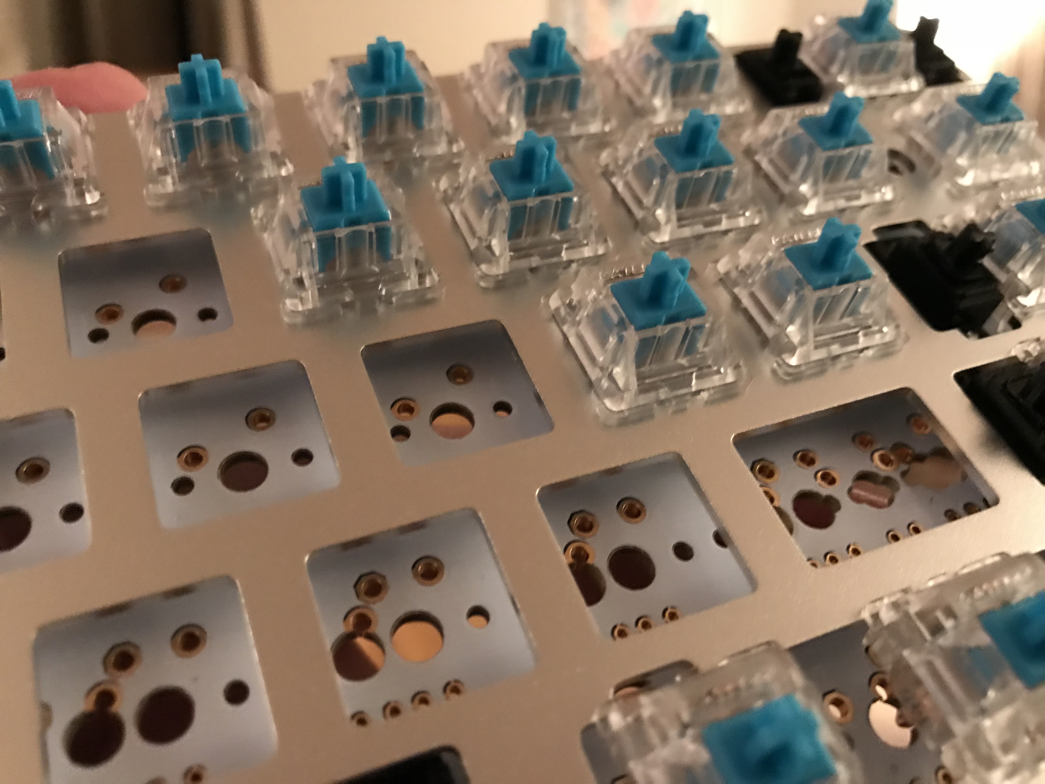
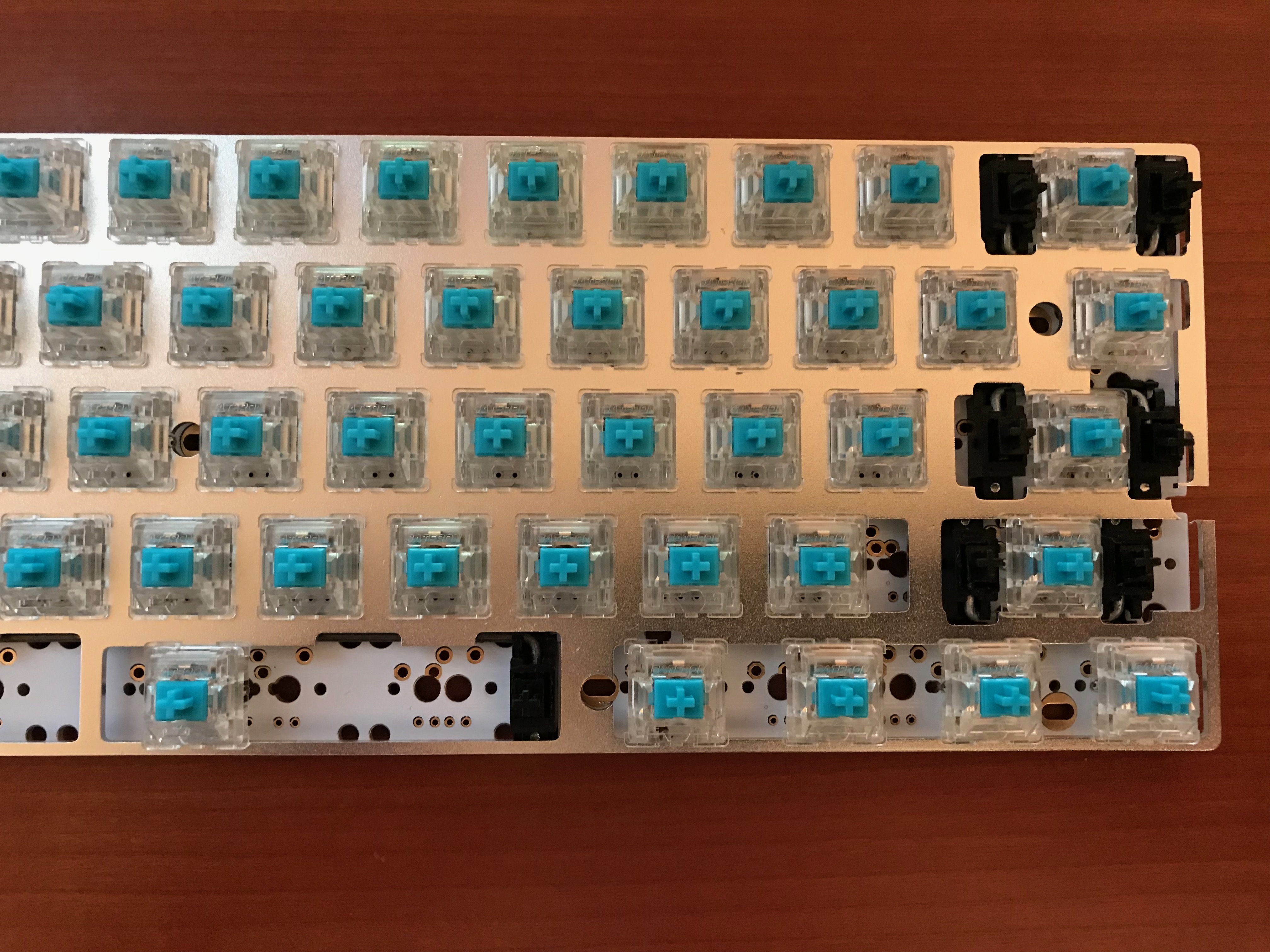
Switch mounting and soldering

Not much to say here - for better or worse, this part of a build is becoming relatively routine.

It was around here, nearing the end of the build (or so I thought at the time), that I realized I’m an idiot. The 92 key firmware and plate support is interesting, but it would be a lot more interesting if the case top actually supported it. Sigh. I guess I have an excuse to go see about machining aluminum now. In the meantime, at least we all know those PHANTOM keys (ha, see what I did there) would work.

Final assembly: case dampening and a custom USB port

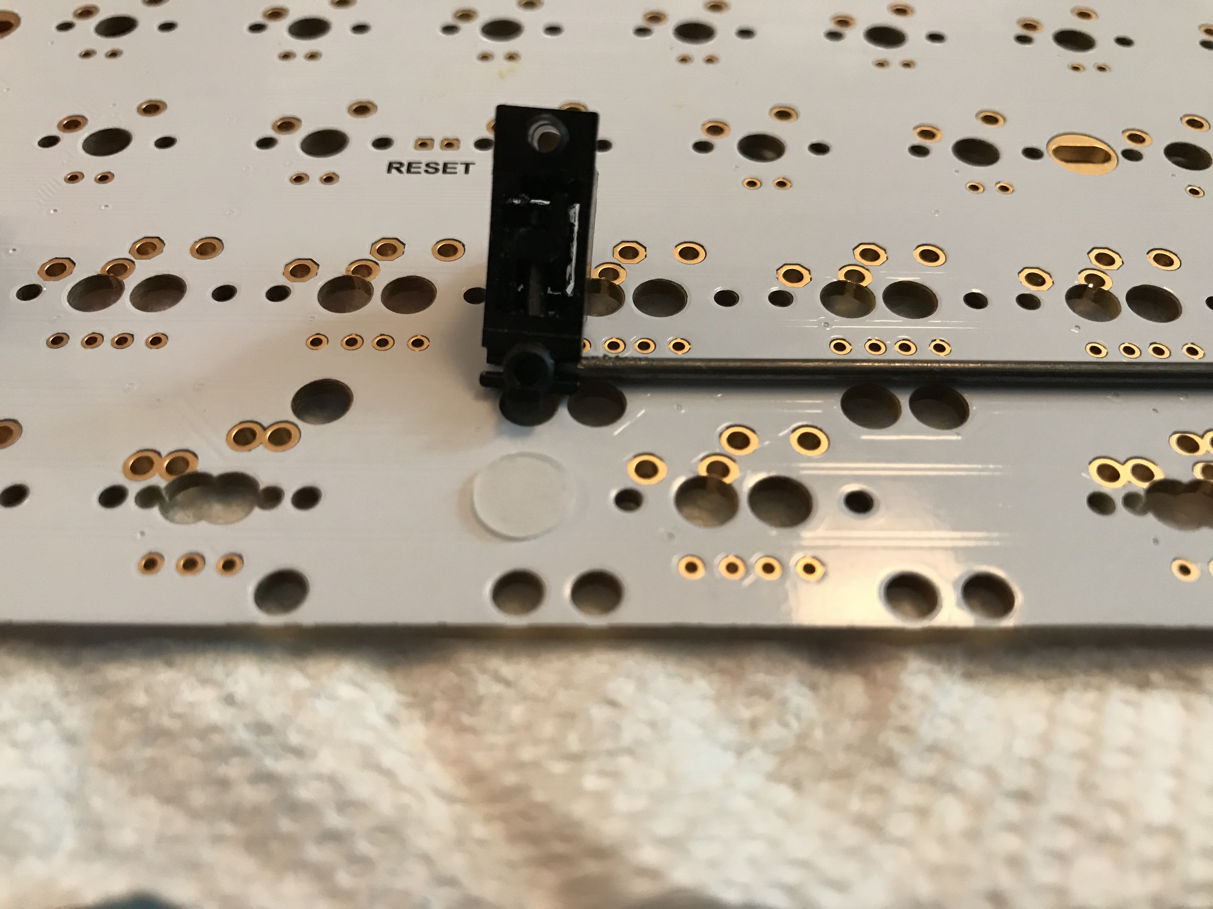
This ended up being the longest part of the entire build, due to my dissatisfaction with the way the Phantom was going to connect to a computer. You may have noticed from earlier photographs that the Teensy has a mini USB port, aimed horizontally across the PCB. The Tex TKL case has an opening where a port would go, but there is no mounting of any kind to hold a USB plug or connector housing - so, you’re meant to plug a USB cable into the Teensy and screw the case together with a cable dangling out of the hole in the back of the case. Having a cable dangling out of an open hole triggers my OCD - I want a female port there, like every other keyboard I’ve built so far.

So what can be done about it? I thought I would get a short male-to-female USB extension, say 6", plug the male end into the Teensy, and then see how to make the female end of the cable fit nicely into the case opening. I didn’t have a clear idea exactly how I was going to make it “fit nicely”, but I assumed some idea would present itself once the cable arrived and I could directly evaluate cable mounting and placement.

The first problem was apparent immediately. The hard plastic housing for the female end of the cable was too big to allow for clean positioning in the case opening, so I had to spend some time gently filing down the plastic until I had created a “shelf” on the housing, allowing the housing to fit flush with the case opening. This was trial-and-error with a needle file, and it took a while to get enough material filed off of the cable housing. Even then, I still hadn’t solved how to mount the filed housing into a stable position.

It was at this point that the next two problems presented themselves. First, plugging the male end of the cable into the Teensy and trying to manually align the PCB with the case revealed that the the male end of the cable was just a bit too thick for the PCB to sit cleanly atop the case bottom. Back to the needle file. Second, and more problematic: the 6" cable was just too long to fit comfortably in the narrow recessed area in the back of the case between the Teensy and the case opening once the PCB/plate was put in place. Sigh. Time to level up to cable splicing.

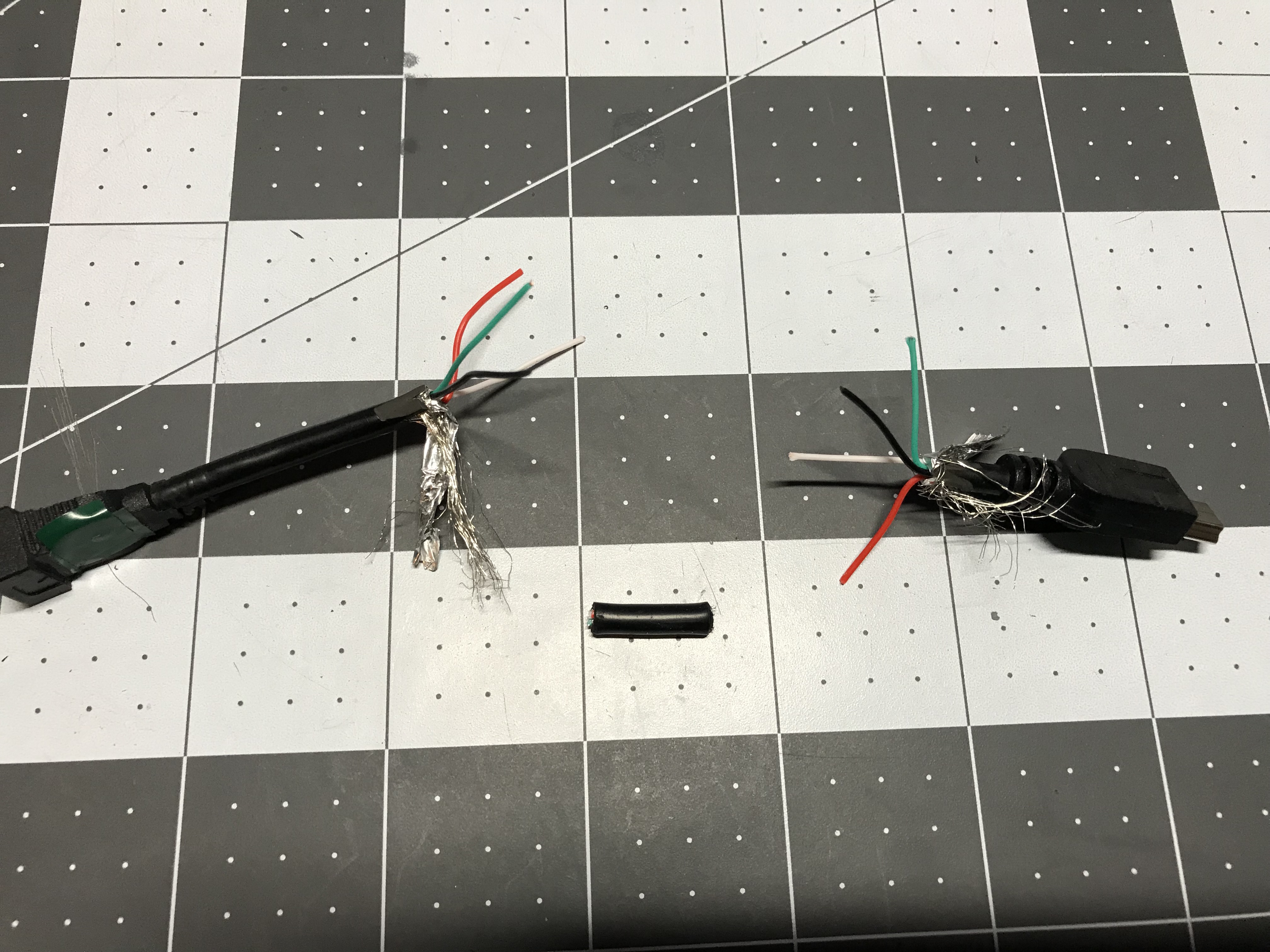
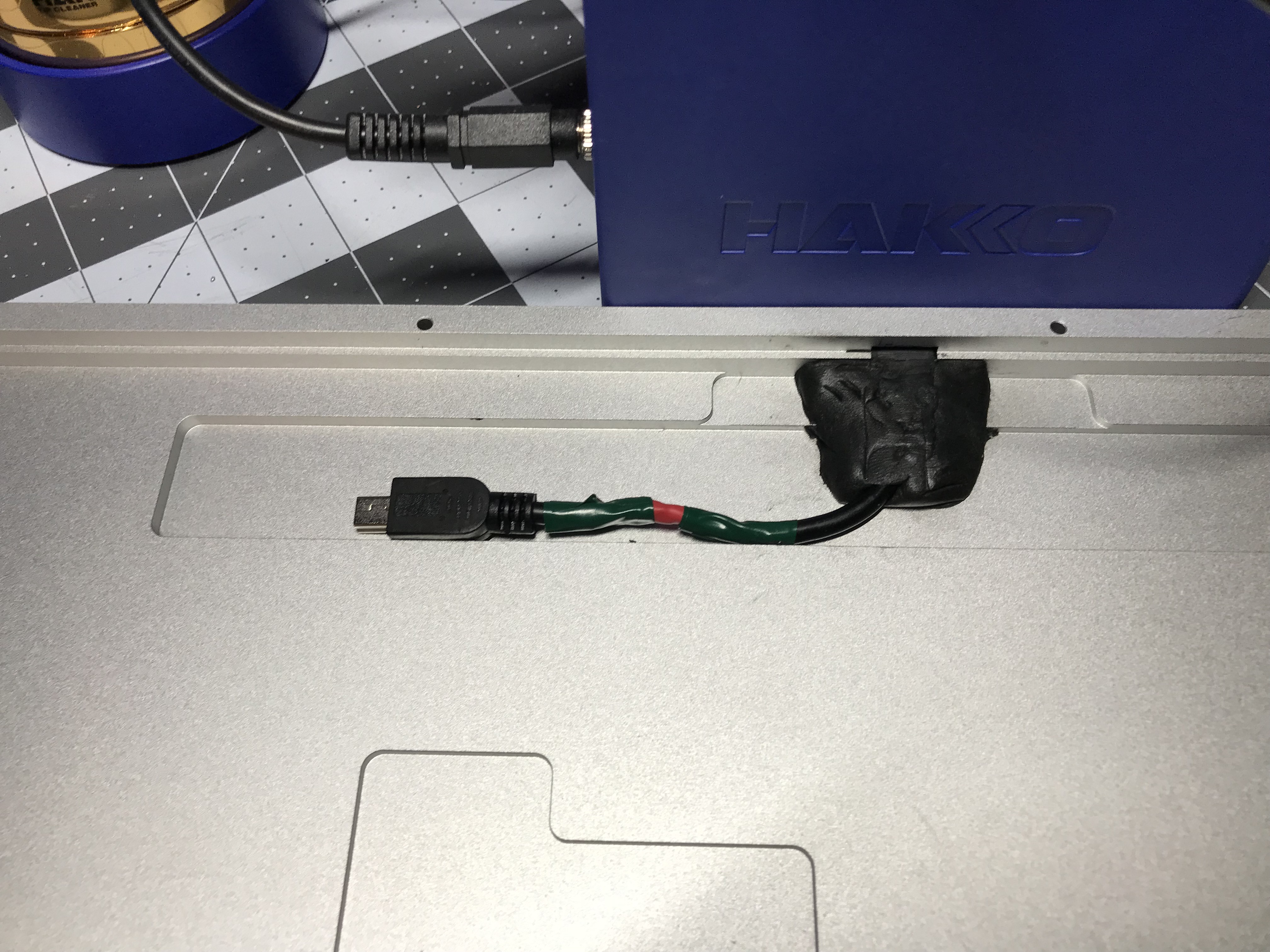
Fortunately, there are any number of guides on splicing USB cables. I was able to cut out a couple of inches of excess cable, strip the outer casing and the ends of the four wires inside the cables, put heat shrink tubing around each of the four wire ends and one larger one around the whole wire, splice the internal wires (color coded, thankfully), solder them together, slide shrink tubing into place over the solder joints, and use a heat gun to shrink the tubing into place. I mismeasured the length of the outer shrink tubing, so I ended up using a bit of electrical tape on either side of the outer shrink tubing to make sure no wire was exposed. Definitely not the prettiest work I’ve ever done, but I ended up with a working ~4" USB extension, which fit just about right in the available space.

Now - how to provide a more permanent fixture for that pesky female USB port in the case opening? I eventually ran across a suggestion to use Sugru for fashioning housings, and after looking at the details, decided to give it a go. When a packet of Sugru is opened, you’ll find a small knob of moldable putty, which you can shape to your heart’s desire, as long as your heart’s desire can be realized in 30 minutes - the time you have available to shape it into the desired form before it begins a 24-hour curing process.

I positioned the female end of the USB cable in the case, and after kneading the Sugru, I manually fashioned a housing, making sure that it made good contact with the case, and making equally sure that it left a bit of vertical clearance for the PCB. 24 hours later, I had a hard silicone miniUSB housing, and, if not exactly a work of sculptural beauty (OK, it’s an ugly knob), at least it’s acceptably solid and stable. Phew.

For the base of the case, to get more sound dampening, I cut a sheet of 0.1" Sorbothane, with cutouts for the Teensy, the cable, and the Sugru plug.

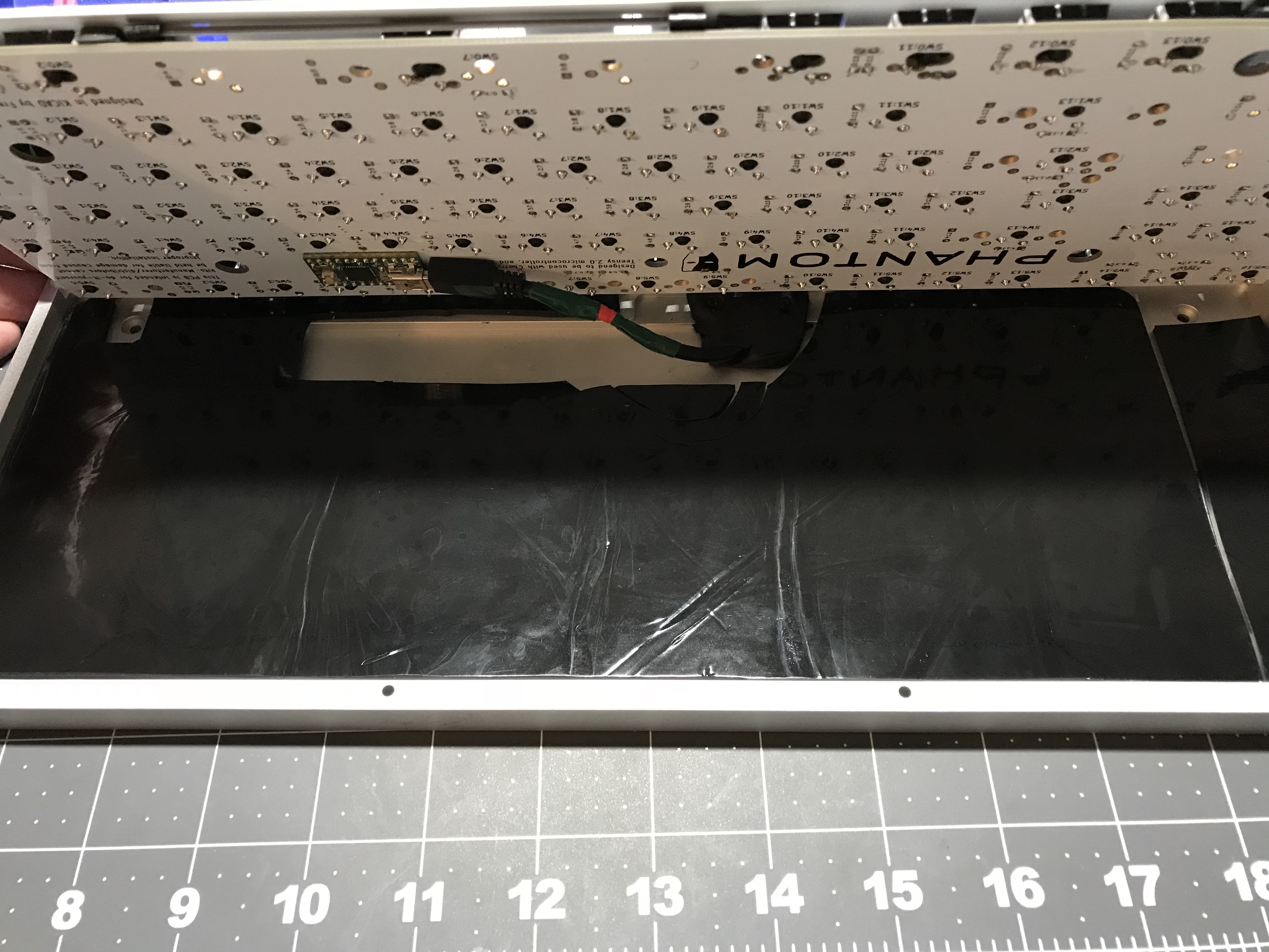
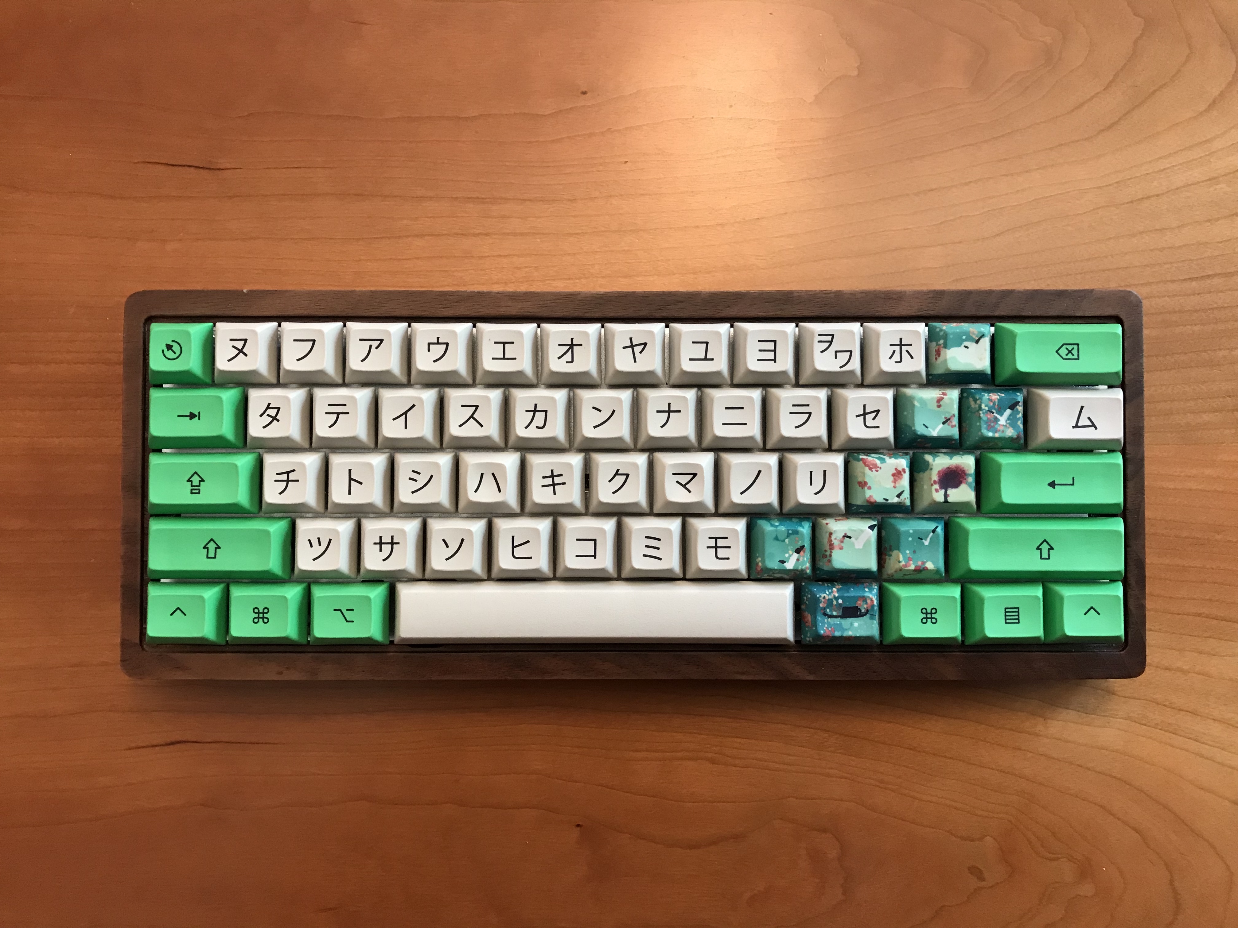
From here, the rest was routine - screw the two halves of the case together and put in keycaps. I’ve got a keyboard! And I can flash new stuff to it! (Note: since the Teensy is now buried inside the case, you won’t be able to get to the reset button to put it in bootloader mode. Shift-shift-pause is the droid you’re looking for.) The Sugru mold turned out OK, too.

And, as a final bonus, the Phantom’s weight is mildly intimidating. Who doesn’t want intimidating heft in their lives? Not this guy.

Lessons learned

  • Sorbothane thickness matters for plate/PCB application. It’s going to be really nice when this parameter is dialed in; even the hack job treatment I applied was still a noticeable sound improvement.
  • Sorbothane is a comparatively expensive case dampening option, but every time I’ve used it, the result is really pleasant, both in sound elimination and added heft.
  • Keep the foam that ICs like the Teensy are shipped in - it’s reusable as a poor man’s mount if you need to do some detailed soldering work and a spare set of hands aren’t available to help out.
  • @Walkerstop is on to something with his stab mods - the fully clipped sliders and O-ring mods are working very well for me on this board. Almost no upstroke noise from any of the stabilized keys, and in fact it really is less upstroke noise than on the unstabilized keys. If this works for PCB-mount stabs, and I don’t know why it wouldn’t, then this is likely to become my standard approach going forward.
  • Lubed MOD-L Tactiles are nice enough, but the stems are more wobbly than those on Zealios, which I still prefer.
  • The barrier to entry for QMK work is not nearly as daunting as it originally seemed, thanks to good project documentation. I’m looking forward to more firmware hacking.
  • Remember those four keys right around the Teensy? The 4 and 5 keys are two of those keys, and what I first thought was stem wobble now looks more like I didn’t get some of the Teensy solder joints as flush as I thought I did - the keys are tilted slightly forward. The MOD-L stem wobble disguised this to some extent, but I suspect I’ll have to go back in and improve those joints.
  • Short cable splices require some care. It’s tough to get the right amount of wire stripped off of the ends of the cut cable, and you want the heat shrink tubing to be long enough to cover your splices, but far enough away from the soldering iron that you don’t prematurely shrink the tubing. I erred too far towards the former problem.
  • Sugru works for fashioning plugs, and so far, the plug seems to be stable when I remove and insert the USB cable. If I were to do it again, I’d spend a bit more time using a straightedge to square off the shape, and even then, if you want the inside of your builds to look as presentable as the outside, this mod is likely not for you.
  • Wear gloves when working with Sugru - it stains the hands, and removing the residue is somewhat difficult. The only suggestion which worked for me at all - rub the stained areas with dry toilet paper(!?). Wasn’t perfect, but was noticeably better than various cleaning agents.

Build resources

I found the following resources helpful for this build (and others), and this build log seems like as good a place as any to give credit where credit is due, when I was able to determine who put up the resource. Also, if one of the unattributed things is yours and I missed you, let me know and I’ll fix it. You deserve the props.

Specifications

case: Tex TKL aluminum (silver)
case mods: spliced USB extension with filed plugs and Sugru fixture
case dampening: sheet of 0.1" 40 Duro Sorbothane, with cutouts for USB cable and Teensy
PCB: Phantom Dual Layer TKL w/ Teensy 2.0 controller
plate: Phantom TKL Anodized Aluminum (silver)
LEDs: Filco-style caps lock & scroll lock: 3mm T1 white (3V, 20mA) w/ 220-ohm resistors
switches: MOD-L Tactile
switch lubing: Tribosys 3204
layout: TKL ANSI (+ the "Phantom 5")
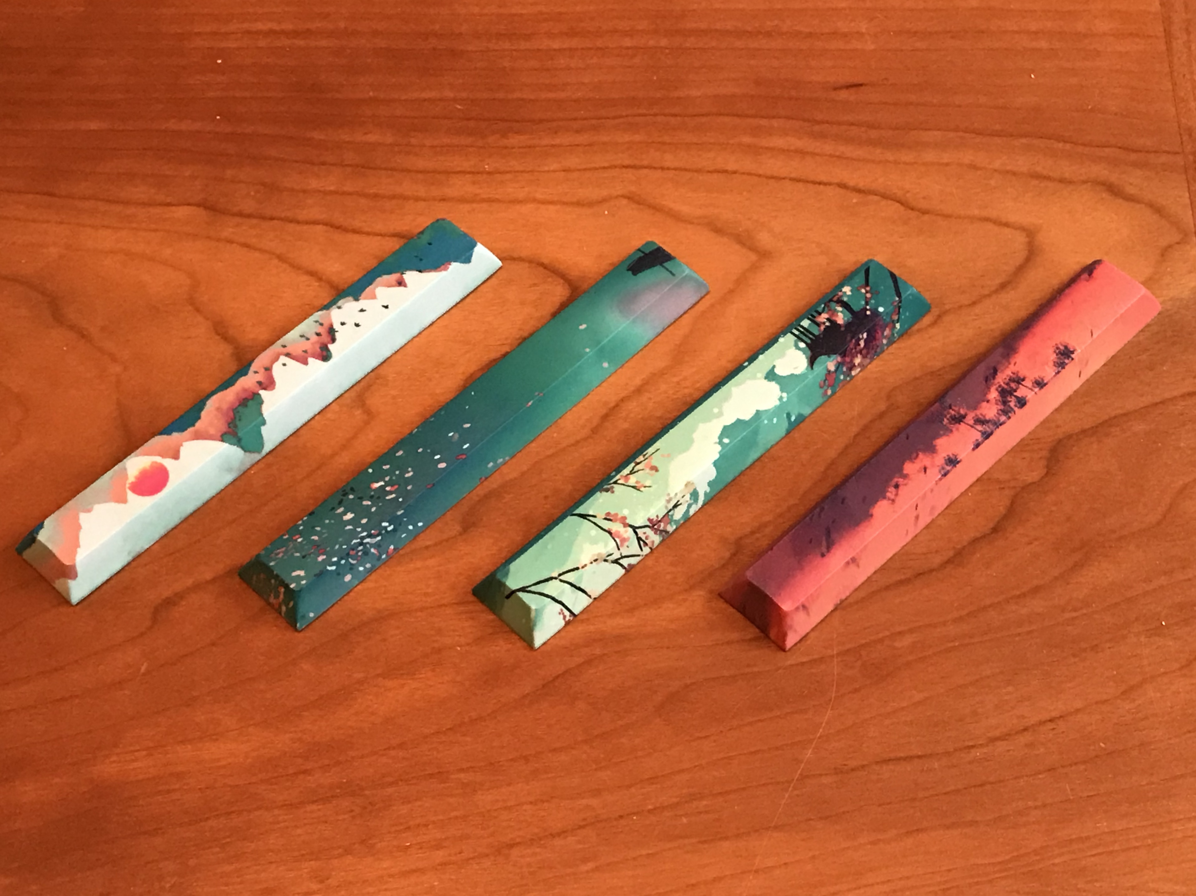
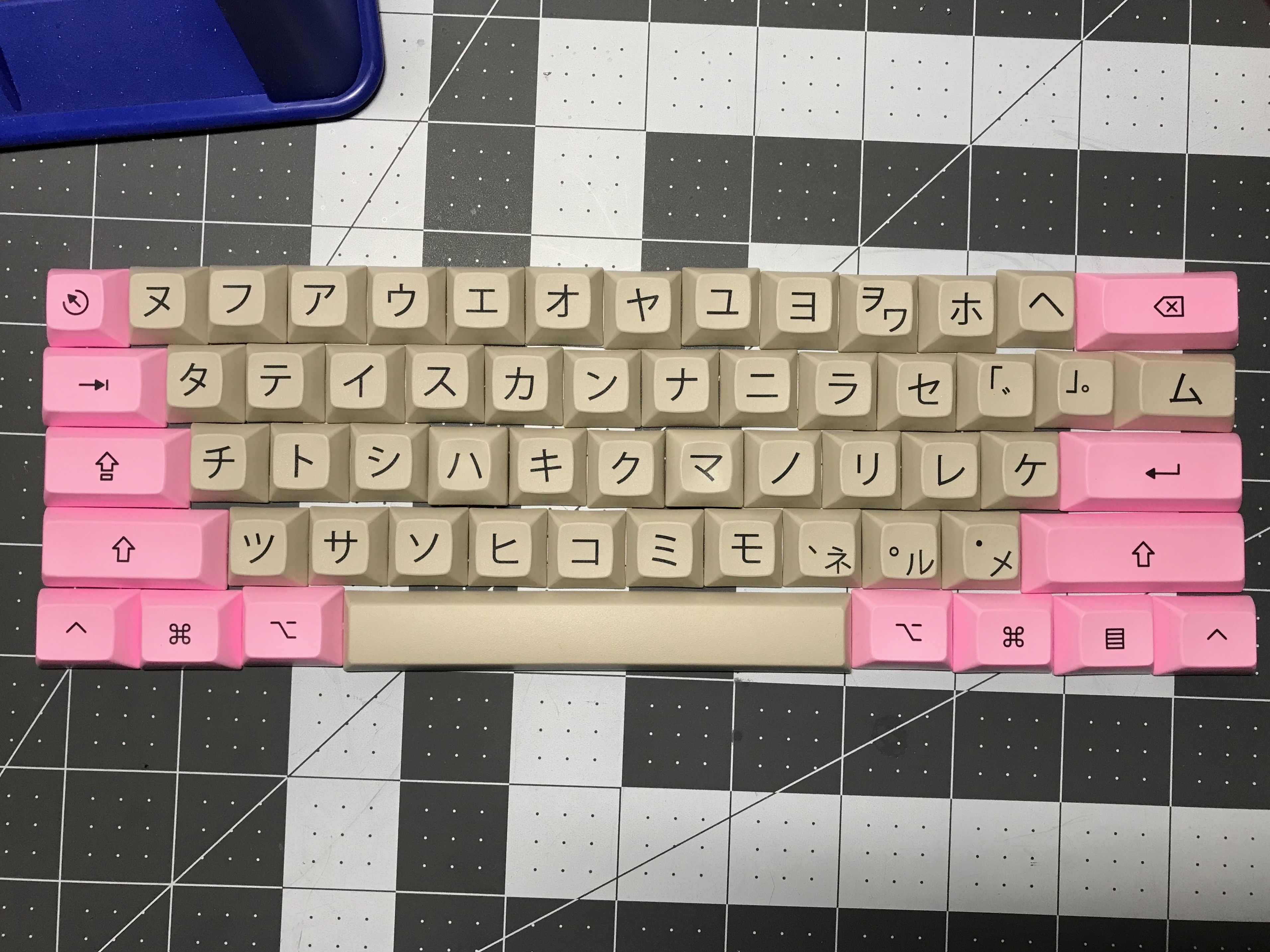
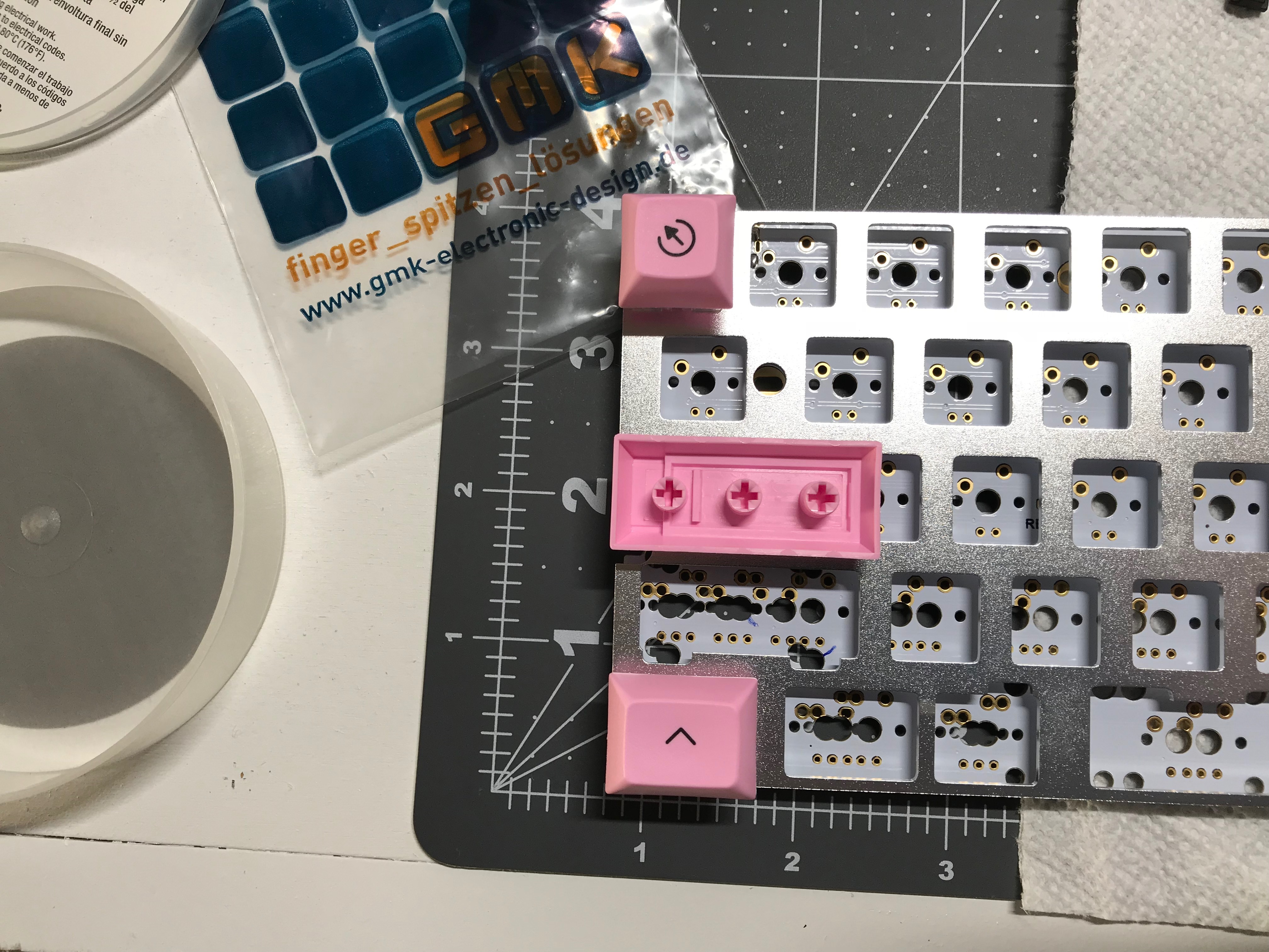
keycaps: SA Foundation (Maxkey)
stabilizer: Cherry plate mount
stabilizer mods: clipped (all four legs); lubed housing, sliders, & wire ends with SuperLube; bandaid-style mod with silicone pads; O-ring upstroke silencing
plate/PCB dampening: 1/4" and 1/8" strips of 0.188" 30 Duro Sorbothane shaved to approx 0.15" thickness
HxWxD (without feet or caps): 0.88" x 14.13" x 5.56"
HxWxD (without caps): 1.25" x 14.13" x 5.56"
HxWxD: 1.75" x 14.13" x 5.56"
assembled weight: 3.69 lbs
6 Likes

Another great build log!

The pictures do a great job illustrating the text. How are you liking the board overall? It seems like a really solid build all around. :slight_smile:

1 Like

Thanks! Overall, pretty happy with it, if for no other reason than I feel like I’m making steady progress towards endgame. At the moment, it’s in rotation with the 67g Zealio Tada (build #1) for daily driving. Will that remain the case? Not sure. The two things I was most happy about with the Phantom build were the lubed switches and the @Walkerstop style stab mods - and the Tada benefits from neither treatment at the moment.

Actually, if I really am getting any better at builds, it probably won’t be the case, because my build backlog is embarrassingly long at the moment, so new daily drivers should be on the horizon, right? I hope the Keebtalk servers have ample storage for build log photos…

2 Likes

Love your builds :slight_smile:

1 Like

Thank you!

This is a really nice build log… quality pictures, attention to detail, lots of information. I like that you addressed dampening the plate, most people don’t do that. I did something kind of similar on my recent 8x build by gluing silicone foam to the backside of the plate using 3mm thick silicone foam, which I think only just barely touches the PCB and maybe not in every spot. but I thin it still helped. Since the 1/8" would be about 3.175 I wonder if that would work better for that purpose?
This is what I did, I think it’s pretty similar:

Also glad the stabilizer mod worked out for you, as far as I know the problem with that mod on PCB mounted stabs is that the slightly different geometry with PCB mount stabs means that if you do this mod, when you pull the keycaps off, you can accidentally pull the slider right out of the stab housing. I didn’t try it myself yet, but this was reported by others who tried it on PCB mount stabs, and when I look at a PCB mount stab and a plate mount stab side by side I can kind of see why that would happen. I will probably still try it at some point just to confirm the issue.

2 Likes

Thanks! Really enjoying all of your recent efforts on switch composition, stabs, lubing - great work. It’s motivating me to dig deeper on my builds.

Speaking of attention to detail, nice work covering all of the plate in the photo above. I wanted to do that with the sorbo, but shaving it to a more appropriate thickness sapped my will to live. At least for sorbo, I wanted something thicker than 1/8" (see analysis here). If that analysis holds, and if it holds for a different material like silicone foam, then 4mm thick strips would be in the sweet spot, and it looks that thickness is available. Any idea about the duro rating of that foam?

Also, thanks for the heads up on issues with the stab mod on PCB mount stabs - this is quite timely information, as I was planning to try that in the next week or so. I assume it’s the clipping of all four legs on the slider that creates the issue?

Sorbothane thicker than 1/8" will be available in R2 :wink:

1 Like

Oooh, you’re making my day.

Geek “arts-and-crafts” (prologue, builds #7-10)

Have you ever wanted to do a build just to see how a keyboard would look in real life?

Usually, I’m building because I’m trying to improve my build skills, or evaluate parts and materials, or try new build approaches, or even all of these at once. Sure, I want the result to look nice, and I do think about the case and the keycaps; finishes, profiles, and colorways are all important. But for the builds I’ve done so far, the primary foci of my endgame quest have been sound and feel.

But this time around, a build was inspired not by the clacks and thocks, nor by the bumps and feels, but by a set of decorative caps - in fact, four builds and four sets of decorative caps. Here are the spacebars from those sets, in a bit of what we call ‘foreshadowing’.

Normally, painted or artisan keycaps don’t get me excited. To my eye, thematic consistency often yields the most appealing results, and the wild deviations from theme that are typical of artisans just end up looking jarring and unappealing. More plainly: when you replace your Dolch escape cap with a neon goblin head, cheers to you, my friend, but I’m sitting this round out.

But there was something about these particular decorative sets that appealed to me. Simple color palettes, consistent styles? I’m in. I thought wooden cases would serve as great backdrops for these nature-themed
caps, and the neutral colors and crisp legends of DSA Otaku would provide alpha coverage without clashing with the decorations. The aggressively red modifiers of DSA Otaku weren’t going to work, but I thought (naively) this would be an easy problem to solve. I mean, it’s just color matching, right? Not a problem.

This is also what we call ‘foreshadowing’.

Meanwhile, at this point, I could have just gone ahead with ordering parts and materials, but I know what I’m about. There needed to be something about these builds that would get me closer to endgame. After some thought, it dawned on me. Four sets of Zilents, 65g vs 67g, unlubed vs lubed, direct comparison. I’ve wanted to try quiet switches for some time, and I’ve seen many mentions of Zilent “scratchiness”, and the beneficial effects of lubing, specifically in regards to these switches, so this project seemed like a great excuse to evaluate Zilents and lubing.

To at least pretend that this little geek arts-and-crafts project has any scientific purpose, I wanted to try to hold everything else constant: DZ60 PCBs, aluminum plates, GMK screw-in stabs, and wooden cases across all four builds, with no attempt to do any case dampening or plate/PCB dampening. The only variables would be switch weighting, presence/absence of lube, and, of course, the decorative keycap choices.

Stay tuned…

Build #7: "Blossom Pavilion"

Here’s a big pile of parts! Let’s get after it.

If you’ve read through all of the preceding build logs, you know the basic drill at this point, so let’s focus on teaching the old dog new tricks.

When I saw the decorative keycaps online, I thought a light pink color would work for the mods, playing off of the spring blossom accents. This is when I discovered that getting the exact color shade and profile you want is, sadly, infeasible. As best as I could tell, the options were these:

  • Design a set and run a group buy. You know, maybe someday? Today, however, is not that day.
  • Raid the kids’ college fund and commission a one-off custom set. Intriguing, but even in the context of this project, a little too far past the crazy bar.
  • Buy existing sets and mix and match caps. We have a winner!

Even so, it’s a winner by split decision - there is a relatively small set of available colors for PBT dye-sub 60% icon mods on PMK, and this more saturated pink was the best I could do. We’ll have to wait for the decorative caps to arrive, but this should work, right?

After trying more aggressive stabilizer lubing in previous builds, and running into problems with sticky stabilizers, I backed off to a slower paintbrush approach with more control. I also opted to do a bandaid-style mod. However, I don’t know about you, but the idea of a bandaid inside my keyboard triggers some kind of weird OCD thing. So, I used vinyl electrical tape instead. Here’s the tape placement for the backspace stabilizers:

And here’s what it looks like with the stabilizer mounted in place. You can see the tape underneath the stabilizer housing.

The DZ60 is known as a “swiss-cheese” PCB due to the number of mounting holes for all of the layout configurations it supports, so I like to make sure I’m putting the switches and stabilizers in the right place. Here, I used a ball-point pen to mark the PCB with the holes I needed to use for an ANSI layout; you can see the pen marks around left shift holes.

Putting the 65g Zilents in.

Do you have an OCD problem like me? Like, you know you’re not going to use backlighting, so there’s no reason to put LEDs in the board, but the board supports it, so, how can you just leave those holes empty? I should look into therapy sometime.

Getting the soldered PCB/plate sandwich into the case:

And, here we are, prior to the arrival of the decorative caps. It’s nice, and while the keys aren’t really silent, they are noticeably quieter and softer than anything I’ve built up to this point, with that nice Zeal tactility. I see the appeal; these are nice switches. I’d also say, however, that I think I get what people are talking about when they say the Zilents are scratchy. The sensation on the downstroke is that of rubbing two almost-smooth-but-not-quite-perfectly-smooth surfaces together, maybe like rubbing two flaps of packaging cardboard together? I wouldn’t go so far as to say it’s bothersome, but I’d bet most people would notice it. The switch lubing experiment coming up in a couple of builds is going to be interesting.

OK, fast forward two months, and now I have the decorative caps. Remember that foreshadowing from the previous build log that introduced this little build series, where I showed you the lovely decorative spacebars?
Welcome to the world of group buys, where, every once in a while, things don’t go quite as planned. When I mounted the first decorative bar in place of the blank one, the spacebar stopped moving. Hmmm. After a few minutes of inspection, it became clear that the alignment of the spacebar’s mount was off. After a few more minutes, it became clear that all of the decorative spacebars were defective. Here, the four defective ones are closest to the camera, and a known good DSA spacebar is in the back.

Hard to see? A straight line makes it more obvious.

Sigh. I had the choice of returning the complete decorative sets for a full refund, or just getting a refund for the decorative caps. I chose the latter, as I felt I could still achieve “the look” I was after with the rest of the decorative sets. But that’s when I discovered the next problem, which was entirely my fault; doing color matching by online photos/renders is a really bad idea. What looked like pale shades of green and pink in the renders turned out to be much more saturated colors in real life, and the saturated colors clashed with the saturated pink mods I had in hand.

So, I paid my penance as one does in this hobby, by waiting for more packages. First, a set of color chips from PMK to determine a better match for the mods, and then new mod icon sets in (hopefully) more suitable colors.

Lessons learned

  • Vinyl electrical tape seems to ever so slightly soften the stabilizer clack, but I wouldn’t say it’s a dramatic difference.
  • Prefer the brush lubing approach on the housing, stems, and wires, even though it takes me quite a bit longer to do it this way; I feel I have more control over the amount of lube being applied.
  • Check for plate warping/bending early on in the build; there was a slight warp at the right CTRL corner of the plate, and trying to deal with it after all the switches were seated on the plate and PCB was a pain.
  • I didn’t want Sorbothane (or any other dampening material) to mask changes in noise between switches as we work through this build series, because, science. But the absence of heft is noticeable, particularly compared with build #4 which had a layer of Sorbothane.
  • Color match with plastic in hand!

Specifications

case: walnut 60%
case mods: N/A
PCB: DZ60 R2
plate: aluminum DZ60 Plate-B (2.25u left shift)
LEDs: white f1.8mm per-key
switches: R11 65g Zilents
switch lubing: N/A
layout: ANSI
keycaps:
- DSA Otaku "Katakana" alphas
- SP DSA sublimated 60% icon mods in green (VCC)
- DSA Landscape "Blossom Pavilion" set, 8x1u, 1x1.25u
stabilizers: GMK screw-in PCB mount
stabilizer mods: clipped, lubed with Permatex Dielectric Grease, "bandaid" mod with vinyl electrical tape
HxWxD (without caps): 1.25"x12"x4.5"
HxWxD: 1.5"x12"x4.5"
assembled weight: 1.41 lbs
3 Likes

I enjoyed reading all your building details :slight_smile: I like how detailed and focused on perfection they are !

Keep on building & sharing the fun with us :slight_smile:

1 Like

I appreciate the kind words, and I’m glad you’re enjoying the logs. Because I’ve learned so much from all of the online build logs, notes, and comments that others have shared, it seems only right to do what I can to share my learning experiences.

As for perfection, well, you might be reading the wrong build logs! :grinning: But it’s fun to try to learn something and get a little better with every build.

1 Like

Build #8: "Koi Pond"

I’ve been talking a pretty good game when it comes to the switch and lubing comparisons for this little build series, and keeping things controlled from build to build. But sometimes you just have to roll with the flow. I had originally planned to use vinyl electrical tape for the stabilizer band-aid mod on all four of these builds, but when I read about an alternative option, adhesive silicone pads, I couldn’t resist giving them a try.

The idea behind the stabilizer band-aid mod makes intuitive sense - absorb some of the stabilizer slider downstroke impact on the PCB with a layer of impact-absorbing material. It’s the choice of material that tweaks my sensibilities. For me, I just never liked the idea of putting bandaid fabric inside a keyboard. I thought there must be other more suitable options for absorbing mechanical impact. When @walkerstop mentioned these silicone pads, I picked up a package and resolved to give them a try in this build, with the conflicting ideas in my head that:

  • There wouldn’t be enough change in stabilizer behavior to affect comparisons across the “geek arts-and-crafts” builds
  • This will be much better than vinyl tape for absorbing impacts and reducing stabilizer noise.

Much better, but not noticeable. Sure!

Hard to beat peel-and-stick for ease of installation. The thickness of these pads is roughly 0.5mm, which wasn’t enough to noticeably affect keystroke travel, and the GMK stabilizer housings were able to clamp down well enough on the silicone. I do think it’s important to align the pads on the imaginary centerline running through the stabilizer mount holes, though, so that when the stabilizer housing is screwed into the PCB, it won’t be off-center relative to the silicone pad and then tilt to one side or the other.

The build proceeded from here in the usual way, and to match the “Koi Pond” decorative keycaps, I had originally chosen a light blue color for the icon mods.

And again, as with the previous build, when the decorative caps actually arrived, the colors were far more saturated than I had anticipated. Remember the color matching I had to do for the previous build? That process actually involved not only that build, but this one, and the next one. Batch mode for color chips and icon mod orders! I suppose I should be happy all of this only involved two shipments instead of six…

The feel of the 67g Zilents is similar to the 67g Zealios, as expected, and differs from the 65g Zilents in the same way that the 67g Zealios differ from the 65g Zealios - a more pronounced tactile bump. As with the previous build, these switches have the same almost-but-not-quite-smooth feeling, particularly on downstrokes. With that said, these really feel quite nice - the combination of relative quiet with tactile springiness makes for a smooth typing experience.

Lessons learned

  • Tried silicone pads as alternative to vinyl electrical tape or bandaids - and like them! Peel-and-stick beats cutting pieces of tape, and I think the feel is a bit more consistent.
  • Still a bit too much lube on one stab stem’s sides, ended up having to remove some excess lube with QTips - probably time to try the @TaehaTypes approach with teflon lube for plastic-on-plastic contact.
  • 67g Zilents feel really nice, but I get why some say these switches are loud. I’ll be diving into switch lubing in the next build.

Specifications

case: rosewood 60%
case mods: N/A
PCB: DZ60 R2
plate: aluminum DZ60 Plate-B (2.25u left shift)
LEDs: blue f1.8mm per-key
switches: R11 67g Zilents
switch lubing: N/A
layout: ANSI
keycaps:
- DSA Otaku "Hiragana" alphas
- SP DSA sublimated 60% icon mods in green (VAZ)
- DSA Landscape "Koi Pond" set, 8x1u, 1x1.25u
stabilizers: GMK screw-in PCB mount
stabilizer mods: clipped, lubed with Permatex Dielectric Grease, "bandaid" mod with adhesive silicone pad
HxWxD (without caps): 1.25"x12"x4.5"
HxWxD: 1.5"x12"x4.5"
assembled weight: 1.53 lbs
1 Like

Build #9: “Mountain View”

Before we get into this build, a quick reminder - these build logs are presented in the order that builds are completed. For this little mini-series of builds, progress was 99% complete, but delayed for a couple months, while I waited for various keycaps to arrive. That convention has some implications for the narrative; namely, that it’s possible that builds I’m writing about now (like this one) document observations which earlier builds appear to exploit (like Build #6, the Phantom TKL build). Specifically, if you’ve already read #6, then you know how this build log is going to end, when it comes to the topic of switch lubing.

Let’s lube

But if you don’t know how this build log is going to end, then let’s get into it. With this build, my primary goal was to get into switch lubing, and determine for myself whether it was worth it. There were a number of resources online for lubing stations, lubing technique, and lube choices, and while there were myriad ways to go about switch lubing, there was one common theme - get comfortable, because switch lubing is time consuming. And it’s tedious. Awesome!

Having never done this before, I tried to become informed, and after reading a couple of useful guides and surfing around, I came away with the following consistent themes:

  • When lubing tactile switches (as I was going to be doing here), don’t lube the side of the slider that has the arms with the bumps, unless you want to lose all of that tactility.
  • If not a full-fledged acrylic or 3D printed switch lubing station, then at least organize the lubing process to allow for assembly-line style lubing.
  • Whatever you do for your assembly-line lubing setup, don’t toss all the springs together - they will become tangled, and you will waste too much time gently untangling them.
  • Lube lightly at first - you can always add lube, but you can’t take it away.

As for choice of lube, I opted for Tribosys 3204. There seem to be a proliferation of lube options, but without having direct experience with any of them, 3204 seemed well-regarded and a reasonable choice for tactile switches.

This first time out, lubing all of the switches took me around five hours. That’s a long time, but I wanted to take my time; I was worried about overlubing the switches, and I was worried about accidentally applying lube to the tactile arms. Also, these are small surfaces to lube, and for this build, I didn’t have the help of any magnification. And, there are lots of those small surfaces - the two slider rails on the bottom housing, the base of the stem and the outside of the stem on the bottom housing, both ends of the spring (inside and out),
the three non-tactile sides of the slider, including the little notched bumps on two of those sides, and the slider peg that sits on the spring. By the end of the lubing process, I was feeling the eye strain.

Also, the MX switch top removal tool is kind of a hassle to use. I frequently found that I could get one side of the switch open easily enough with the tool, but then trying to open the opposite side would often cause the first side to snap back into place. Annoying. I finally got into a rhythm where this didn’t happen very often, but I didn’t find it pleasant to use this tool.

Pro tip: if you’re old and your eyes are getting worse (and perhaps even if they’re not), do yourself a favor and
get some kind of magnification setup. I got a magnifying lamp after this project, and it has really made a substantial difference in reducing eye strain, for not only switch lubing, but also switch and LED soldering. Your eyes will thank you! I went nuts and got a wide-angle Luxo with an astonishingly heavy base, but really, even a basic free-standing magnifying lamp would work.

First observation, after lubing the very first switch: wow, that pinging noise I was hearing was spring noise - and it’s gone. Completely.

Second observation, after playing with a single lubed and reassembled switch: oh, that’s smooth. Buttery smooth. And no more scratchy sensation on the downstroke.

At this point, I was pretty excited to get these into a board and try them out, but before that, I needed to mod my stabs. I tried Teflon lube initially for this build, but it wasn’t working for me - the lube tended to “powder off” from the application points, and even when it stayed in place, it wasn’t as smooth as the Permatex dielectric grease. Abandoning that, I switched over to SuperLube to give it a try, and found that while SuperLube isn’t dramatically different from Permatex in consistency, it seemed just a tiny bit less viscous. Because of that, I felt I had better control in the application of the lube to the stabs.

Onward. With stabs mounted and switches and LEDs soldered, it was time to put the caps on. As with the previous two builds, I had already pre-selected a color for the icon mods.

And as with the previous two builds, when the decorative caps arrived, it became clear that the initial icon mod color choice wasn’t the right one to pair with those caps. In this case, a saturated blue worked well with the mountain graphics on the decorative caps.

I like the 67g Zealios on good old Build #1, but these lubed 65g Zilents are nice and certainly competitive as potential daily drivers for me. Super smooth and responsive, good tactility, and quite quiet; lubed Zilents would be a great choice for your shared office, if you’d prefer not to annoy your colleagues with your clacks. My only issue has nothing to do with the lubing, but the spring weight; I still find the 65g versions to be just a bit too light under the fingers. Based on this experience, I’m quite excited for the next and final build in the geek arts-and-crafts series - will lubed 67g Zilents provide the magic I seek?

Lessons learned

  • I was really hoping I wouldn’t get sucked into the world of switch lubing, but if this first experience is indicative, then there’s no getting around it - the difference between this build and the “Blossom Pavilion” build is non-negligible. Clear improvement in feel and sound. “Buttery” feel seems to be the right descriptor.
  • While I got by with a few small Akro-Mils bins to setup an assembly line, I suspect a switch mod station would be helpful to get a much faster lubing assembly line going (see Build #6 for the experience with an acrylic switch station!)
  • A single switch opening tool would be preferable to the MX top opening tool, at least without a switch mod station - I found that often, the side that I had just popped open would lock back into place when I popped the opposite side.
  • So far, I think I like SuperLube best for stabs - it seems just a bit thinner than the Permatex, and that’s making a difference for me during lube application.

Specifications

case: walnut 60%
case mods: N/A
PCB: DZ60 R2
plate: aluminum DZ60 Plate-B (2.25u left shift)
LEDs: white f1.8mm per-key
switches: R11 65g Zilents
switch lubing: Tribosys 3204
layout: ANSI
keycaps:
- DSA Otaku "Katakana" alphas
- SP DSA sublimated 60% icon mods in blue (BCT)
- DSA Landscape "Mountain View" set, 8x1u, 1x1.25u
stabilizers: GMK screw-in PCB mount
stabilizer mods: clipped, lubed with SuperLube, "bandaid" mod with adhesive silicone pads
HxWxD (without caps): 1.25"x12"x4.5"
HxWxD: 1.5"x12"x4.5"
assembled weight: 1.38 lbs

Build #10: “Sunset Country”

The previous three builds have been, well, building towards this one. Prior to starting this geek arts-and-crafts series, I’ve been a fan of the 67g Zealios, and after experiencing the benefits of switch lubing firsthand in the previous build, I had high hopes for lubed 67g Zilents. Same tactility, silent buttery feel? What a wonderful world that would be.

Here’s the problem with the DZ60. If you’re installing backlighting LEDs and you use screw-mount stabs, you will find that one of the screws will short out the LED on the enter key, next to the R60 resistor. As this was the first time I’ve encountered this issue, I didn’t have any nylon washers on hand. The solution I used is a little janky, but it works: use one or two pieces of electrical tape as an insulating layer between the screw and the trace.

Other than that, this was one of the most trouble-free builds I’ve had. Clipped, SuperLubed, and silicone-padded stabs? Check. 3204-lubed switches? Check. Soldered switches and LEDs? Check. Case assembly? Check. Properly color-matched icon mods from the get-go? For the first and only time in this
series…check! Let’s call that one lucky.

And, as expected, 3204-lubed 67g Zilents deliver a wonderful typing experience. Very smooth, just the right amount of tactility, and quiet. For me, definitely an endgame contender, and eerily reminiscent of what I remember all these years later as my holy grail typing experience, which I’m 90% sure was this IBM RT board from the late 80s. Which reminds me - I really need to make an appointment with a Topre board and some BKE Redux Ultra Lights.

I really wanted lubing to be one of those things that only the crazy people did. Guess what? I’m now one of those crazy people.

Lessons learned

  • Nylon washers would be handy to have around.
  • Buy some extra switches in the event you discover your potential endgame switch mere days before the entire line is discontinued for V2! Sigh. These things happen. Looking forward to the V2 Zilents…

Specifications

case: rosewood 60%
case mods: N/A
PCB: DZ60 R2
plate: aluminum DZ60 Plate-B (2.25u left shift)
LEDs: orange f1.8mm per-key
switches: R11 67g Zilents
switch lubing: Tribosys 3204
layout: ANSI
keycaps:
- DSA Otaku "Hiragana" alphas
- SP DSA sublimated 60% icon mods in orange (OAZ)
- DSA Landscape "Sunset Country" set, 8x1u, 1x1.25u
stabilizers: GMK screw-in PCB mount
stabilizer mods: clipped, lubed with SuperLube, "bandaid" mod with adhesive silicone pad
HxWxD (without caps): 1.25"x12"x4.5"
HxWxD: 1.5"x12"x4.5"
assembled weight: 1.67 lbs
1 Like

Geek arts-and-crafts (epilogue, builds #7-10)

It started as an arts-and-crafts build series, and it’ll end that way, but I did manage to learn something. Lubing switches is time-consuming, and it can be tedious, but even after just two tries, it’s pretty clear to me that it’s worth doing. Spring ping is eliminated, and feel is noticeably improved. If you’ve been reading along, and you’re on the fence, I’d recommend giving lubing a try with your favorite switches.

Family album

I’m not a photographer, and so far I’ve resisted the urge to pick up yet another expensive and limitless hobby. But that doesn’t mean we can’t have a little fun.

7 Likes

I absolutely love your build logs. I don’t check this site much, but this thread is an instant click every time I see there are new posts.

1 Like

Wow. Thank you! I hope you continue to enjoy the build logs ahead…

1 Like

Build #11: KBD19x

So far, my build adventure has taken me through form factors ranging from an ortholinear to a TKL, and while I’ve been playing a lot with 60s, and enjoying them, I continue to think of TKL as my endgame form factor. Up until recently, I’ve also been thinking of TKL as the last stop before a full-size board. I mean, what else could you really do to grab some desk space back from that full-size board, other than lopping off the numpad?

Cue a suitably reverberant voice of omnipotence: you have much to learn, my son.

Yes, back in build #6, I had a near-miss with “TKL+5”, the idea of inserting the “missing” five 1u keys into the space above the arrow cluster. But even then, somehow the idea of moving the numpad to the left and throwing the intervening keys away, rather than throwing the numpad away, just hadn’t occurred to me. With the popularity of 1800s on the rise, though, it was only a matter of time until I saw one and the light bulb went off. And, there is something kind of interesting about jamming an arrow cluster back into the space between the numpad and the alpha cluster - it seemed ugly at first, but it’s growing on me.

Finally, whether or not I liked the 1800 experience, I’ve been finding that doing builds with different form factors is a great way to challenge my build skills, as well as my firmware skills. So I was excited to try something in the 1800 space, and after poking around to look at build alternatives, I eventually settled on the KBD19x kit. It’s a little weird in that it’s not quite a true 1800 (it’s missing the four-key delete row that you’d see on a G80-1800), but it has an extra key right after the function keys, where an LED indicator trio might normally be. Still looks like a good time.

The only downside here that I could see was the lack of support in the GitHub QMK repo. After the initial QMK experience in build #6, adding layout support for the Phantom “TKL+5” to the repo, and looking at all of the amazing functionality @drashna has built in his userspace configuration, I became very interested in building out a shared set of key mappings and macros for all of my boards. While the KBD19x is nominally supported by QMK, that’s through a separate web configuration tool, not via the standard repo, which for me was a problem. Having invested the time to standardize my mappings across the rest of my boards, I didn’t want to have to deal with a special snowflake - I wanted to build the firmware for all of my boards in as standardized a way as I possibly could. After spending some quality time with the QMK documentation, I made a decision: if KBD19x support isn’t in the repo by the time I need it, I’ll add it. Hopefully that wasn’t a crazy idea?

And, let’s be honest. There is one more reason to like these somewhat larger form factors. When you drop serious coin for a quality keycap set, it’s kind of a shame when a substantial fraction of the set goes unused on a smaller board. Would that concern ever really stop me from going with a smaller board? No, it wouldn’t, but I’d be lying if I said that I didn’t think “nice, I’ll get to see more of that keyset on this build.”

Switch treatment

After the switch lubing experiences during the “geek arts-and-crafts” series, a little internal dialogue takes place every time I need to prepare switches for a build.

Me: Ugh, I have to lube all these switches. There goes the better part of a day. Do I really have to do this?
Me: You suck. Have you completely forgotten how nice it is to type on lubed switches? Man up.

Properly self-chastened, I got comfy, fired up a long playlist, and got to work. I found it best to do these in batches of 15, the width of my acrylic switch lubing station. This made it straightforward to lube assembly-line style, and it also gave me convenient breakpoints for standing up and stretching my legs. As it happened, real life intruded, so the task ended up getting split over a couple of days. But, eventually, I had a little plastic bin full of 100 lightly lubed Zealios.

Stabilizer treatment

The received wisdom is clear. GMK screw-in PCB-mount stabs, or death. There can be only one. But on inspection, the stabs that came with the KBD19x kit honestly didn’t appear or feel appreciably different from the GMK screw-ins. Not wobbly, or at least no more so than any other stabs, including GMK, that I’ve tried.
While I had spare GMK sets I could have used, after some momentary waffling I resolved to go ahead and use the OEM ones.

In a previous build log, I was excited to try the full @Walkerstop upstroke silencing mods on PCB mount stabs, but his comments in response to that log gave me pause. Apparently others had reported that after doing this mod, keycap removal caused the stabs to pop right out. That mod has two departures from the “standard” stabilizer treatment: clipping of all four legs on the sliders, and O-ring insertion. It seemed to me that eliminating all four legs would have to be the reason for the sliders to pop out, so I opted for a partial upstroke silencing treatment: only clip the usual two legs of the slider, but do the O-ring insertion. As it happens, the two legs we would normally clip were already gone from the sliders of these OEM stabs.

So, the job just boiled down to the usual SuperLube treatment, and some careful tweezer work to get the O-rings into the stabilizer housing and threaded onto the stab wires. Here’s what the O-ring placement looks like when the stabilizer is put back together, from a couple of different angles:


After a quick bandaid-style mod with adhesive silicone pads, the stabs were ready to be mounted. The KBD19x kit came with plastic washers for the screws, which was a good thing since the PCB looked very much as though it was designed and manufactured by the same group as the DZ60, and if you read previous build logs, you’ll remember that I have had issues with stab screws shorting out traces on that board. So, having washers at the ready to guard against those problems is nice, although it’s worth noting that some of the installed washers overlap the edge of the PCB, and one even bends up over a diode that’s within a washer’s radius. Not so great.

Sorbothane, part 1

You will have seen by now that I like Sorbothane for sound dampening applications. You’ll also have seen that I’m still on a quest to properly dial in its usage for keyboards. One of the problems I’ve been wrestling is getting strips of the right thickness to sandwich between the PCB and the plate. Too little thickness, and the Sorbo can’t touch both the plate and PCB, reducing its effectiveness for sound dampening. Too thick, and undesirable excess pressure will be applied to the plate and/or PCB when the sandwich is assembled.

In another thread, I estimated 4mm as a reasonable thickness for Sorbothane when sandwiched between a standard 1.5mm plate and the PCB. That thickness isn’t currently readily available, but we can approximate it, to some extent, by cutting 4mm strips from thick pads of Sorbothane. I used a metal ruler to first mark off a bunch of dots 4mm away from the edge of the Sorbothane pad, and then I used the ruler to connect the dots and trace a cutting line with a ball-point pen (pro tip: leave the protective plastic on the Sorbothane pads while you do all of this, so you don’t have to worry about sticking to the Sorbothane). Then, just cut down the line as best you can. I used 0.25" (6.35mm) thick pads of Sorbothane as my starting point, and once I had enough 4mm wide strips, I just laid them on the plate on their sides.

How did I know if this was doing anything useful? Before-and-after tap testing, which is pretty much exactly what it sounds like. Before layering in the Sorbo, put the plate and PCB together with a few switches, and tap the plate with your finger and/or fingernail, all around the plate, while holding the whole assembly close to your ear. Listen. Then, after putting Sorbo on the plate where you want it to go, repeat the process. If your experience is like mine, you’ll hear a high-frequency ringing with your fingernail on the plate before the Sorbothane application, and that will go away almost completely even with a few strips of Sorbothane in place, leaving a more bass-heavy thunk. Whether this is an improvement is a matter of taste, but for me, it’s very much an improvement.

It’s also nice that only a few pieces were needed to eliminate the lion’s share of the high-frequency plate noises. Sorbothane isn’t the cheapest option out there, so it’s nice to be able to stretch the supply through more builds.

Porting to QMK when it’s kind of ported already

With the PCB/Sorbothane/plate sandwich lined up, switches were mounted and soldered, and the keyboard was flashed with an initial hex file built with qmkeyboard.cn. A few minutes with tweezers and a keyboard tester web app, and the initial build is functional.

I said I was going to do it, and it’s time: let’s build out support for KBD19x in the QMK repo. On the plus side, I’m intimately familiar with C/C++ in a variety of application domains, and the QMK documentation for doing a keyboard port looks pretty complete and easy to follow. On the down side, none of those application domains included embedded programming, and none of my version control experience included git. So, there’s still going to be a learning curve here. Time to get stuck in.

First of all, for QMK to support a PCB, it needs to support the controller. The controller is the chip on the PCB that does the matrix scan (more on that in a moment). While I’m willing to attempt a port for a controller that QMK already knows about, I’m pretty sure that writing core support for a new controller is currently beyond my pay grade, so I need to confirm that the controller is one that QMK already knows about. I’m 99.9999% sure that must be the case, since the qmkeyboard.cn site claims QMK support, but I’m me, so I check the chip anyway. Atmega32U4, yes, we’re good.

Next, the wiring matrix and the matrix scan. As I understand it, the controller on a PCB determines key activity by repeatedly lighting up one row of the matrix with some current, and then seeing which columns also show current coming through when that row is turned on. Those row-column pairs correspond to switches that have been depressed to allow current to flow through. The controller keeps track of those row-column pairs, turns off the row, lights up the next row, and repeats the process. When this process has been executed for every row, that’s called a matrix scan, and the controller does that scan many times per second to track key presses and key releases. For the controller to “know” which row-column corresponds to each switch, it needs to know which key corresponds to each row-column coordinate pair in the wiring matrix. It stands to reason that the firmware we build must include a description of the wiring matrix, in order to properly translate row-column pairs into the correct keys. So how do we figure out what the wiring matrix is?

If I was really porting a keyboard from scratch, with just a PCB in my hand, I’d have to work out the wiring matrix for the keys by visually inspecting where the traces connect to the controller. Even under a magnifier, this would be painful - the traces are the same color as the PCB (for this PCB, anyway), they’re very narrow, they’re often in close proximity to one another, and they can pass through to the other side of the PCB to “jump” over other traces without forming an electrical connection.

Fortunately, I was able to bypass the bulk of this pain. The qmkeyboard.cn site actually provides a “Wiring” tab which not only shows the wiring matrix for the boards it supports, but also shows the row and column for a key when the key is clicked. So, I started by manually recording the row/column pair for each key in the web interface. In the QMK code, this information is recorded in a LAYOUT macro for the keyboard, which provides both the wiring matrix for firmware compilation, and provides a nicer interface for subsequent QMK developers. With a LAYOUT macro, you can stare at code that is organized like the actual keyboard layout, rather than the rat’s nest of a wiring matrix you’ve been staring at. It took a little time to build out this macro and double-check the mapping from keys to row-column pairs, but it’s more careful bookkeeping than anything else.

Similarly, the website provided pin assignments for backlighting and RGB control, as well as available memory limitations for the controller - all information that QMK needs to compile a complete firmware for the board in the form of a .hex file. Again, this isn’t hard per se, but it requires due diligence to make sure the correct information is being coded. Again, I need to give a shout-out to the QMK docs. Descriptions of the required information, and how to supply it to the code, were quite clear, at least to this C developer. Love that.

After fixing a couple of typos, and checking all my data entry again, the code compiled cleanly, and there’s a brand-new .hex file for the KBD19x. Oh boy. The reported memory sizes are good, so this should easily fit on the Atmega, and there are no errors, and I’ve triple-checked all of the information, so there’s no reason this shouldn’t work. Still, oh dear. I just sat for a few minutes thinking it over before finally committing and flashing the firmware to my PCB with QMK Toolbox. Looks like the PCB is still alive? Time for the keyboard tester and tweezers again…

If plugging in Build #1 and having it actually work was the single best experience I’ve had with this hobby to date, then flashing the firmware for this kind-of-reverse-engineered port to QMK and finding that it worked, first time, certainly qualifies as at least a very strong second. Damn, that was satisfying. I’m going to go have a celebratory glass of wine. Be back in a moment.

Full disclosure: while the firmware really did work, I discovered later that the .json file I provided for key position and sizing wasn’t showing up correctly in QMK’s own web configurator project. But before I realized I had a problem, let alone worked out how to diagnose and resolve it, @noroadsleft had already found my problem (a stray character in the file) and fixed it. Cheers, buddy.

From here, it was just a matter of process - a pull request, code review and changes, and there we are - it’s in the repo. Cool beans.

LEDs

The underglow RGB LEDs are already soldered into the PCB, but it’s up to me to put in LEDs not only for key backlighting, but also for the caps lock, scroll lock, and num lock indicators. The way this is done on the KBD19x is really quite sexy; the case top has three machined “tunnels” in the cross strut in which the LEDs can shine upward, and instead of actual holes at the top, the case is micro-perforated, so light can shine through when the LEDs are on, but when the lights are off, these three spots are featureless anodized aluminum, just like the rest of the case. Nice. I used orange, blue, and white LEDs for these, as that’s what I had on hand.


Now. If you’re doing key backlighting on the KBD19x, and in particular, on both 2u keys on the numpad, learn from my mistake. Normally, I solder in all switches first, and then thread the LEDs through the switches before soldering. But with the 2u numpad keys on the kbd19x, this will not work, because the LED pads for these two keys are not aligned with the holes in the switch sitting above them. Yes, really. Try as you may, you are not going to be able to thread the LED pins through the soldered-in switch and then somehow get them to bend enough to make the necessary turn to reach the pad holes on the PCB for these two keys. Or if you can, I demand video. Because I didn’t detect this issue until it was too late, I ended up having to desolder and remove these two switches, threading the LED pins through the switch holes while the switches were out, and then mounting the switch and threading the switch and LED pins in place and soldering. A nightmare fix?Well, no, but an annoying hassle? Yes.

Sorbothane, part 2

We’ve done the PCB/plate sandwich. Now it’s time to dampen the case. The PCB has the underglow RGB LEDs and an acrylic spacer to show off that glow, so I had to measure out pieces of Sorbothane that would lie inside the imaginary perimeter of the underglow LEDs, as not to obscure all those Rs and Gs and Bs. In addition, I wanted to leave a cutout for the controller, to avoid putting any undue pressure on the PCB at that point. Look at me, all thinking ahead and stuff. Also, taking some measurements to estimate the gap between the PCB underside and the interior bottom of the case, I found that a 3/16" (0.188") layer of Sorbothane, which I already had in hand, would be about right for contact with the PCB and the case, so with a few minutes of measuring and cutting, the case dampening was in place.

I carefully peeled the protective adhesive layer off of both sides of the acrylic spacer (take your time, the spacer that comes with the KBD19x kit is flexible and fragile). In a nice touch, the spacer has cutouts that align with pegs on the case to assist in placement. From there, it’s just a matter of lining up the other half of the case and screwing everything together.

Sorbothane, part 2b

I threw on a set of caps and tried the board out, and discovered immediately that I had a problem. While most keys felt quite nice and sounded wonderful (switch lube + GMK + Sorbothane FTW), the enter and backspace keys were very sticky, and required undue force for downstrokes. I tried to convince myself this would work itself out, but eventually the conscientious part of me won out over the lazy part of me, and the case was opened again. Note to others - if you have direct Sorbothane contact between the PCB and case, and you find you have to separate them, take your time prying them apart. Sorbothane is quite sticky, and we don’t want to fracture the PCB.

As soon as I separated the PCB and the case, I had the presence of mind to try the enter and backspace keys again, and wait, what? They work now, just fine. Inspecting more closely, I realized what the issue was - the Sorbothane was pressing the clip mount of the stabilizer housing on one side of each of the two affected keys, hard enough to force the stabilizer housings slightly off of vertical, creating excessive friction on the stabilizer sliders. Solution? Cut away more Sorbothane to avoid pushing the stabilizer housings out of alignment.

While I was doing this cutting to relieve pressure on the stabilizer housing, I noticed that one of my Sorbothane squares was actually applying pressure to the reset button on the PCB. I wonder how long it would have been until the board started dropping into bootloader mode for no discernible reason? That’s right, look at me, all thinking ahead and stuff. Sigh. Let’s cut some more Sorbothane, shall we. That’s good.
Probably best not to let me out of the home without adult supervision.

As an aside, with all this aluminum and Sorbothane, this keyboard is heavy. Quite heavy. I wouldn’t want to drop this thing on my foot.

Speaking of weight…

So it’s all put together, and I’m typing, and it’s very nice - the sounds are really pleasing. This is my first time with real GMK caps, and it really is a step up from the cheaper, thinner Cherry profile caps. These yield a lovely soft clack, and with the switch lubing and Sorbothane, that’s all we hear. Nice.

But we haven’t talked about switches yet. I’m in the middle of an experiment - the switches on this board are R11 78g Zealios. This was somewhat unintentional, in that I thought I was lubing 67g Zealios before I noticed, 20 or so switches into the lubing assembly line, that the switches were a bit too stiff, investigated, and realized I was lubing 78s.

I’ve thought that my tastes run to the middle-of-the-road for spring weightings, and I’ve generally felt most comfortable on the 65g and 67g Zealios. However, I wanted to see what I thought of switches with comfortable tactility, but heavier weighting (not necessarily on this build, but what the hell, it was going to happen anyway at some point, so let’s just run with it). On a switch tester, I wasn’t entirely sold with the 78s, but then again, that was a switch tester. I think the switch tester is great for ruling out switches you know you’re not going to like, but for switches you’re not sure about, I think the only real way to be sure is to try out a board with them.

And, initially, I thought that even with the lovely sound and lubed smoothness, these springs were really just a bit too heavy. Normally, I’d just switch back to another board immediately for daily driving at that point, and I’m not really sure why I didn’t do that this time. Maybe I didn’t want to give up the melody of the clacks? In any case, after a week or so, the feel started to grow on me. I found I was bottoming out less often, and riding the tactile bump more often. Even more interesting, after going back to build #1 (TADA68 with 67g Zealios), I ended up switching right back to this board. Hmmmm. Getting all these variables dialed in turns out to be a more subtle optimization than I imagined. That voice. It’s back again…

…you have much to learn, my son…

In the meantime, these keys and that sound? It’s all good. While it took me 10 more builds, and while it may not be endgame, I have a new daily driver. Progress!

Lessons learned

  • 78g isn’t as firm as I might have guessed from just playing with a switch tester. I’m enjoying the weight more than I thought I would. Perhaps it’s a good idea to just live with a set of switches for a while…and perhaps I need to get a hotswap board sometime soon for just this purpose.
  • I’ve spent enough time with this board and these switches that the difference in weight is less noticeable in an absolute sense than it was before. Not sure if that’s because I’m getting used to the weight, or perhaps the springs are being broken in a bit? Something else to evaluate.
  • Be careful when placing Sorbothane. Under sufficient compression, it can push the clip-end of a stabilizer housing and deflect the stabilizer off-vertical, leading to compromised keystroke performance. It’s best to just create cutouts where this might be an issue.
  • With that said, the combination of Sorbo dampening, switch lubing, and GMK caps yields a delightful sound, the best of any board I’ve built to date. It’s the sound of hard raindrops on the roof.
  • A sparse Sorbothane treatment between the PCB and plate can be remarkably effective for dampening - and cost effective, if you plan to do multiple builds.
  • If you’re doing LED backlighting, check the LED pad positioning to be sure the LED can cleanly pass through the switch and through the pads. For any keys for which this isn’t the case, it will be far easier to thread the LED pins through the switch first, before seating the switch on the PCB.

And, a special lesson on color

As you’ll see in a moment, I’m getting to the point where I need to think about doing proper color calibration for my build logs. This build had a lot going on color-wise - blue anodized aluminum case, and GMK Solarized Dark for keycaps. Having seen this build in a number of different lighting situations, I understand both why there has been so much drama around the set in terms of color accuracy, and why opinions on its looks are all over the place. Depending on what time of day it is and whether I have lights on in my office, my opinion changes too. This really crystallized for me when I got around to taking and comparing photos of the build. Same board, same caps, same cell phone camera - just different background and lighting. What a difference!

Indoors, under LED lighting on a desk:

Outdoors, under direct sunlight on asphalt:

Specifications

case: KBD19x anodized aluminum (blue)
case dampening: 0.188" 30 Duro Sorbothane, trimmed to fit inside underglow LEDs and away from stabilizer clips and ICs
PCB: KBD19x
plate: KBD19x stainless steel
LEDs: blue f1.8mm per-key
switches: R11 78g Zealios
switch lubing: Tribosys 3204
layout: ANSI
keycaps: GMK Solarized Dark
stabilizer: OEM screw-in PCB mount, pre-clipped
stabilizer mods: lubed housing, sliders, & wire ends with SuperLube, bandaid-style mod with silicone pads,
  O-ring upstroke silencing
plate/PCB dampening: ~4mm wide strips of 0.25" 50 Duro Sorbothane, laid sideways on widest struts of plate
HxWxD (without feet or caps): 1.25"x15.06"x5.75"
HxWxD (without caps): 1.38"x15.06"x5.75"
HxWxD: 1.88"x15.06"x5.75"
assembled weight: 5.30 lbs
4 Likes