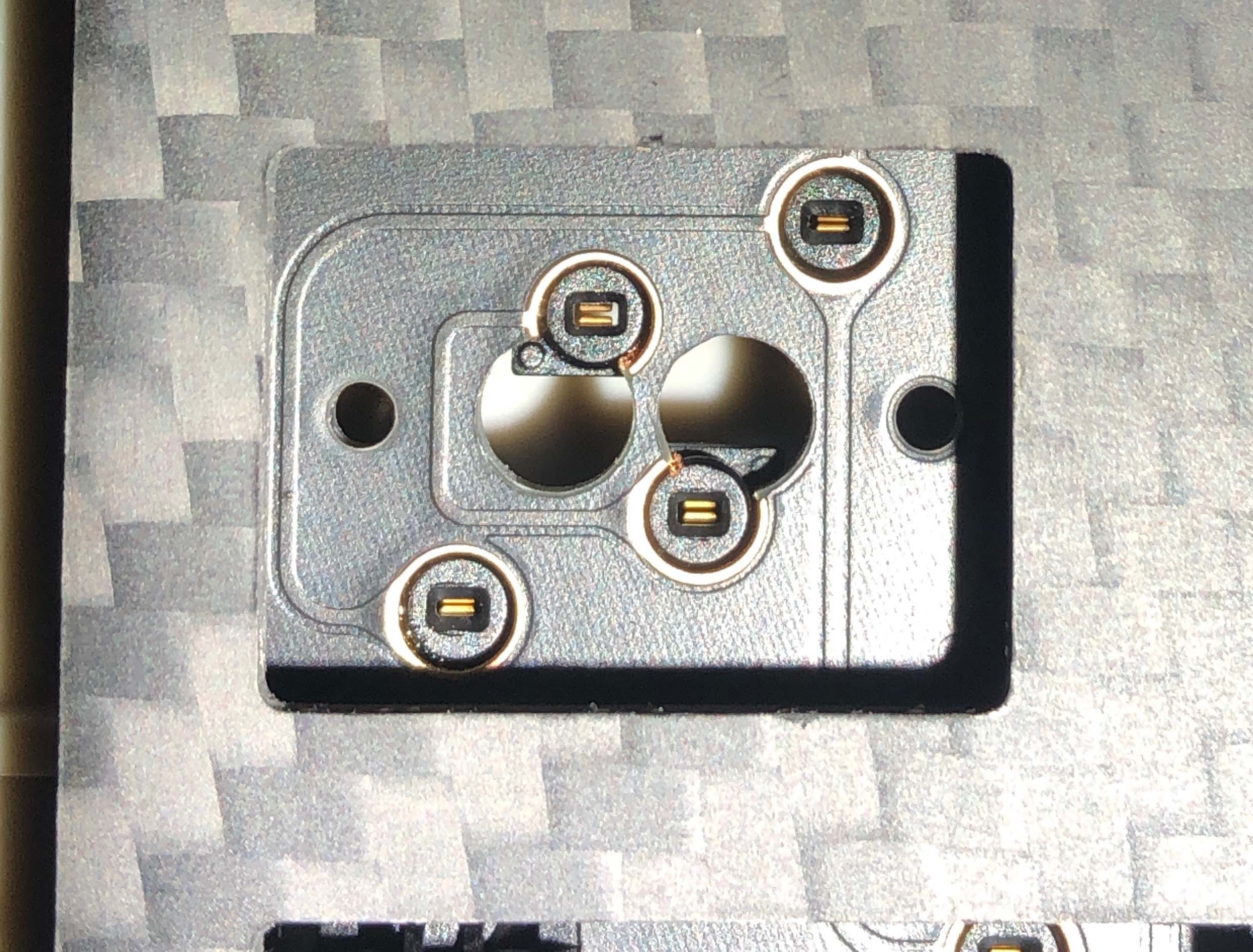
Discovered an interesting little challenge with my hotswap NCR80 which arrived today…
Notice how the hotswap sockets obscure the capslock central switch pin hole…!
I know this can be rectified with desoldering one of the sockets or alternatively reshaping the switch pin, so no big deal.
Just wondered if anyone has seen similar undocumented features on other pcb’s 
2 Likes
Looks like some minor dremel action may be required 
I feel like the sockets are soldered wrong but can’t tell. Can you show a photo of the back of the PCB?
here is a very grainy pic of the mode 80 that has both stepped caps lock and regular caps lock.
Should not interfere with each other. Mode Designs
3 Likes
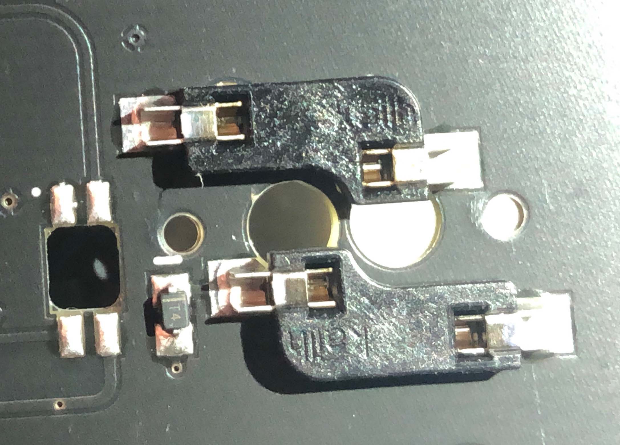
The problem appears to be the way they aligned the sockets.
Notice in the mode, the switch leg nearest the mounting hole is placed on the outside. On the NCR, they are placed on the inside.
So instead of a frame like this
   ____
  o  o |
|____
We have more like this
     _____
   o | o
  ____|
At least, that’s what I’m seeing.
Edit: man those are some rough drawings, rooski.
4 Likes
How can you sell something like that …
here’s the underside. I’m hoping that I can just reflow the pads and push the sockets enough to clear the holes.
Looks a little marginal to me…Actually, there’s no point - I think I’ll just remove the stepped socket
2 Likes
That is frustrating. I think removing the socket that is in the way is the best move. Or drilling the stem post holes. You can’t really shove it out of the way because the way the sockets are made there is not that much play.
1 Like
Yup, but don’t lift a pad in the process as this could cut in half some important traces.
Do you have a hot air station ?
All you need here is a socket I think