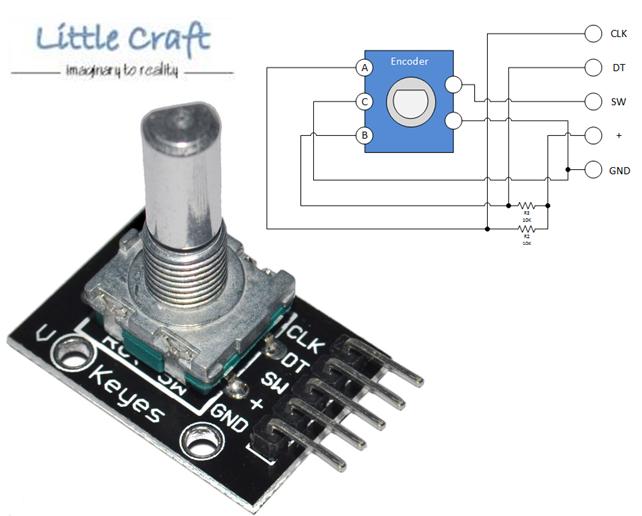
So I have this rotary encoder → https://cdn3.volusion.com/btfzd.umflq/v/vspfiles/photos/AD267-2.jpg?1462545819. It has 5 pins - CLK, DT, SW, + and GND. From what I understand, I can plug CLK and DT on any pin, plug + to VCC and GND to Ground. For the switch part, I really have no idea on this. In QMK, I need to provide the row and column pins but this only has 1 more pin. Also, how do I include the encoder, at least the switch part, on the switch matrix?
1 Like
my guess is that they wire the button like this
so it would cost you a whole pin just for this button
I think it would be better to use the encoder “raw”. You will need 2 pins for reading the encoder, the “button” can be wired as other switch.
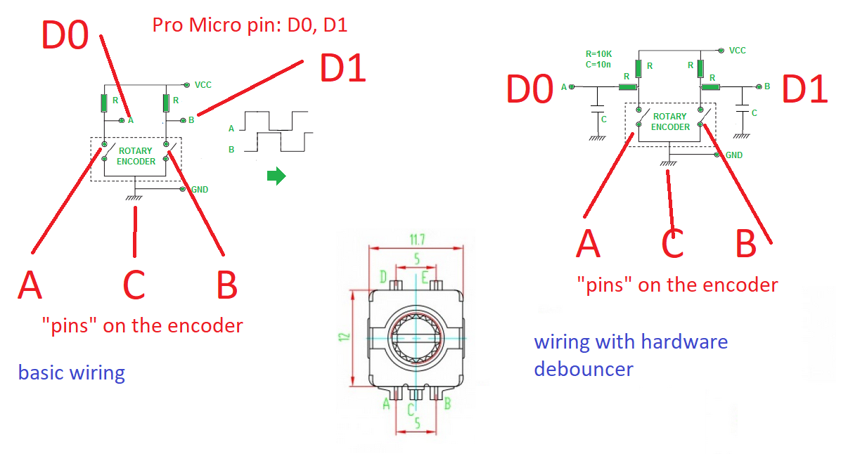
I wire the encoder like this (image from google)
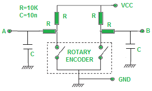
(this includes hardware debouncer)
it works flawlessly.
Thanks for the reply.
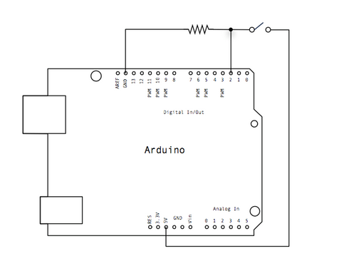
I got one “raw” encoder. I am using the BDN9 firmware from keeb.io and wired it up. I got the mute working but cannot get the volume up/down working. Wired it to D0 and D1 and also tried it to F5 and F6 with no success. I directly wired it to the pro micro though. Do I need resistors?
yes you need resistor.
R = resistor, 10k ohm.
read more: https://www.electroschematics.com/12012/rotary-encoder-arduino/
about volume up/down, I’m not sure how BDN9 firmware read the encoder value, do they use QMK? with QMK, you need a slight delay between registering keyup / keydown. (source: https://www.reddit.com/r/olkb/comments/9jzbg1/help_with_rotary_encoder_code/e8elobo)
Yes, the BDN9 uses qmk. Its a macropad by keeb.io. It has 2 rotary encoders that uses the D0 and D1 for the volume control and F5 and F6 for page up and page down.
Turns out my wiring is correct the first time. It was the code. I compiled it just now and it’s working now. I got the previous hex through QMK Configurator.
A bit of a necro, but I’m working on a board with some encoders at the moment and had to look up how they interect in order to add them, so I figured I’d add my findings to this thread.
Seems the most common encoder to use just for fitment and convenience is an Alps EC11 vertical mount with five pins(technically seven if you count the mounting tabs like you do the PCB-mount legs on switches) usually with two on the “north” side and three on the “south” side based on their used orientation.
From the datasheet I’m referencing.
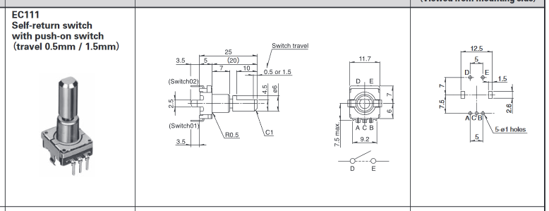
The two on the north side(D, E) are for the built in vertical SPST switch, for all intents and purposes used exactly like a normal switch in the matrix up to just sticking those pins right up next to switch pins on the footprint. These pins are not shown in the diagrams in the comments above, those are only showing specifically the encoder circuit and its bits.
The three on the south side(A, B, C) are your actual encoder pins. Tl:dr, they basically at like two switches that are pushed/released sequentially with the order being determined by either clockwise or counterclockwise rotation. For QMK usage A and B are tied directly to their own pins on the board while C is tied to ground.
From the datasheet again is the basic recommended electrical use case for the encoders
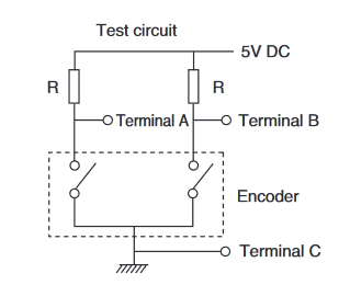
The diagram does show a 5v connection and resistors that are irrelevant to our use case since pretty much any controllers we are utilizing are already internally pulling the data pins high.
To address the previously posted diagram and the hardware debounce:
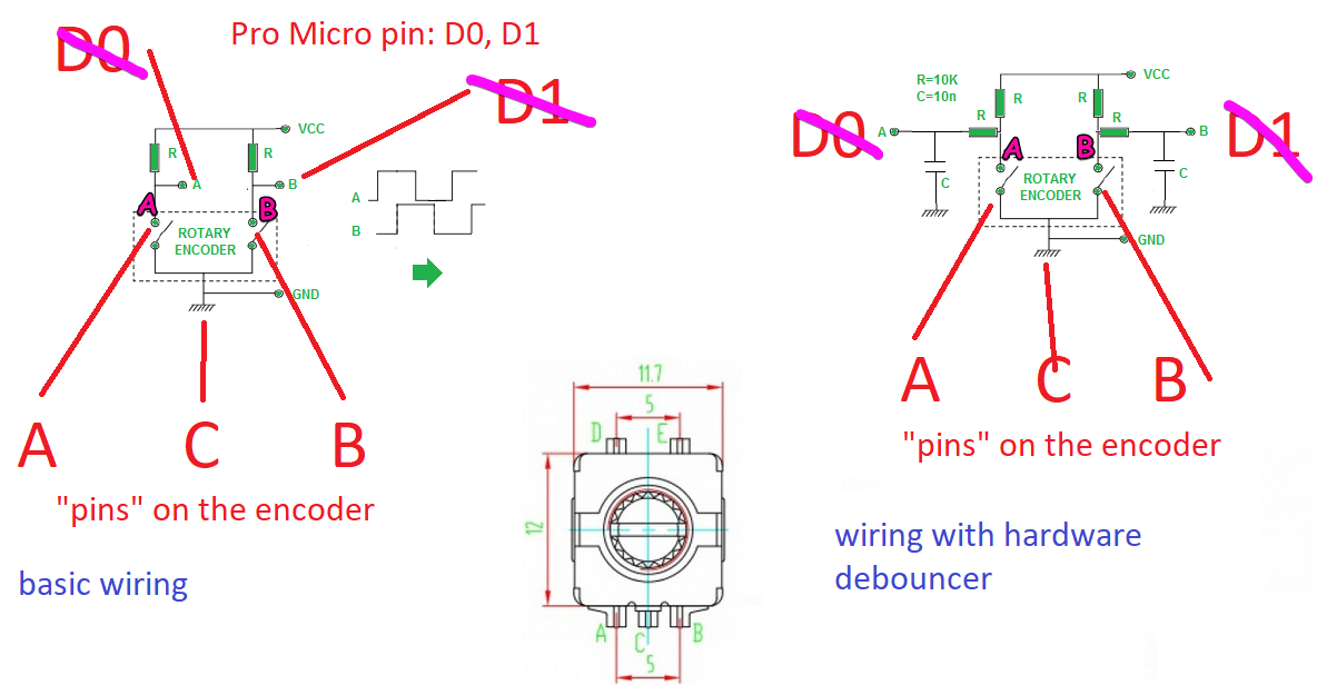
Again, this is just addressing the encoder end of the switch and not the simple switch portion. I will say the diagram is a little misleading since it’s using terminal dots to indicate incoming connection instead of where that connection actually meets the device pins. If you’re feeling picky and don’t think that QMK will deal with potential debounce to your liking, simply add a decoupling capacitor along the data pins, a resistor between the data pin and the encoder terminal, and then the regular pull up resistor between the encoder terminal and Vcc. The decoupling caps act just like they do when used on a controller, to smooth out spikes and drops in the power supplied and the extra resistor acts to dampen the data pin being pulled low to keep the signal cleaner.
For anyone looking to add an encoder, most five pin encoders with a push button should follow this same general setup, which is easy to test with a multi meter: the two on their own should connect when the button is pushed and be disconnected when unpressed, the three you should see a cycling connection between either of the outer two to the middle one.
Hopefully this is all useful information I’ve spent the past hour spewing onto the screen 
Of note is this one I found that looks very similar to the one OP found:
In its current form this will not work for adding onto most normal matrix setups because the second pin of the push switch is connected to ground instead of a row/column pin. This will work for stuff setup like the Keebio BDN9 that is using direct-pins; ie a single data pin for each switch and all connected to ground, a method for low numbers of switches that means no diodes are needed.
If you wanted to adapt this particular “encoder-on-board” setup, you’d need to cut the trace going from the second switch pin to ground and run that as a separate wire. Personally, I would also cut the + trace just past the pin(since we have built in pullup) and run the jumper wire to that to have everything still just need to plug into those pins.
2 Likes