amazing… please keep us updated.
This keyboard looks really great, so I’m planning to build one.
But before, I have a few questions:
- Switches: Do only the “Kailh Choc Switches” fit the PCB, or do the “Kailh Choc V2 Switches” fit as well?
(The most difficult part seems to be: How/where to buy the switches and keycaps… (and of course, how to label them, since I don’t like unlabeled keycaps.)) - Diodes: Is there a reason why you’ve put the diodes on the top side of the PCB and not on the bottom side? They might be hard to replace on the top side – but maybe they never have to be replaced, I don’t know…
- Additional keys: Other keybords have e.g. 2 additional keys “in the split”, so e.g. an “Enter” and “Backspace” key, which then can be pressed with the thumbs. What do you think about such keys, and would it be sensible to add them?
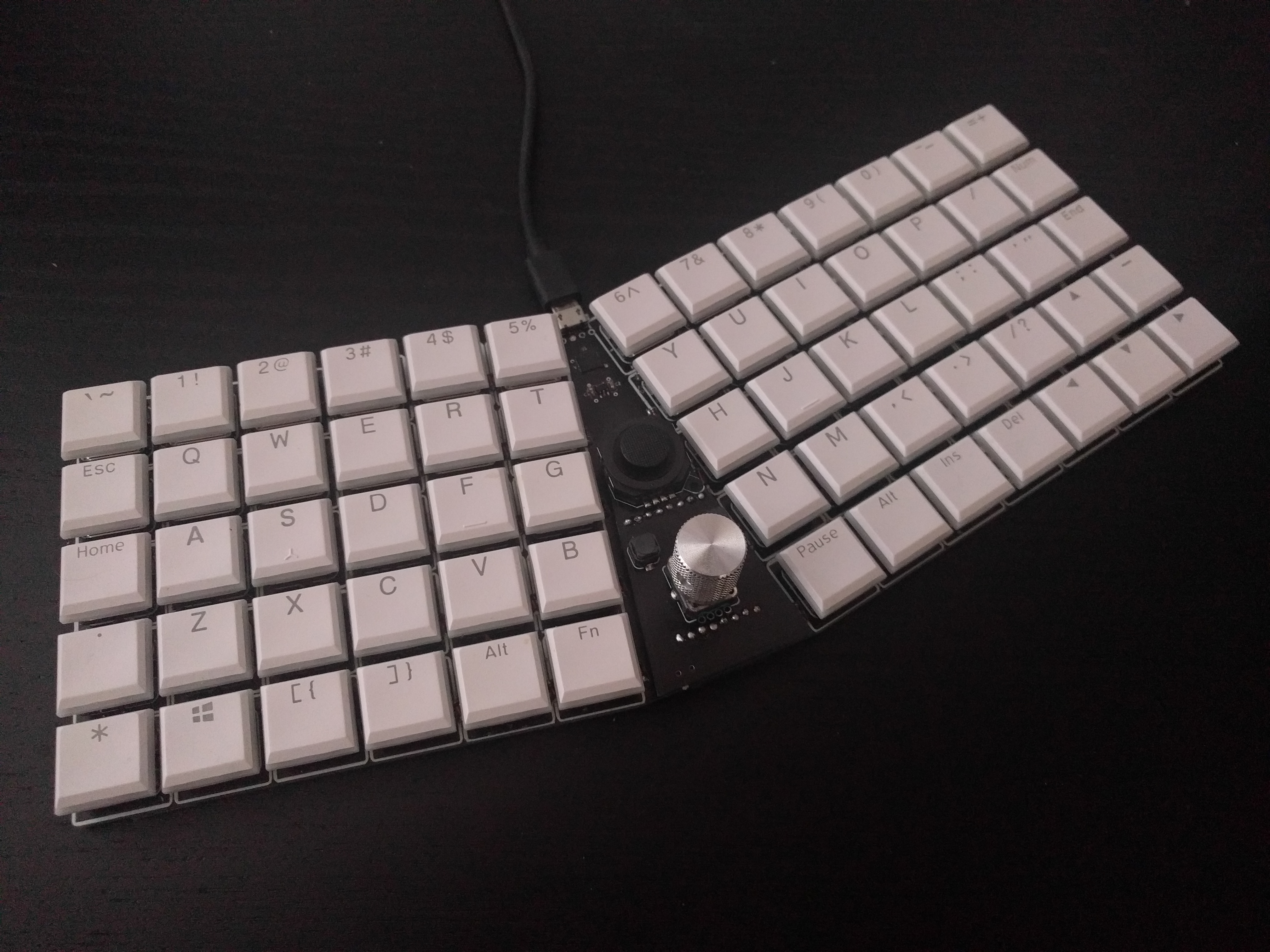
- The V2 switches require larger central hole and one more pin in the top right corner, so they won’t fit on this PCB, sorry. I bought my switches and keycaps from the official Kailh store on Aliexpress. The keycaps I got are double-shot, with transparent and white/black plastic (I think white looks much better, the black is kinda bleak and gray). Of course I had to be a bit creative for all keys that are bigger than 1U, so my spacebar is “Pause”, my enter is “End”, my backspace is “Num” (think nomnom for eating the characters). Other keys like ctrl or shift are symbols from the numpad, etc.
- I have never heard about a properly soldered diode failing. Just test they are properly soldered before adding the switches and you should be fine. The reason all the parts are on the top is that the PCB is lying flat on the desk, with just some thin rubberized stickers on there, because I wanted it to be as flat as possible. I have also cut the legs of the switches to be flush with the PCB.
- The last version has pin headers with power and all the remaining microcontroller GPIO pins exposed on them. The plan is to make a number of small PCB modules with different things on them: a joystick, a knob, additional keys, maybe even a display or gesture sensor. It’s definitely sensible to add them, but of course then you will probably want to modify the layout as well to make better use of them.
1 Like
sorry if this is a dumb question. trying to learn about this stuff. does the voltage regulator remove the need for the decoupling capacitors around the chip? i was looking at a “minimal configuration” diagram and it seems like it would need a few more caps. it also seems like you need an external crystal if you want to use the analog pins? is that wrong?
There are two decoupling capacitors — one on the 3.3V rail, to smoothen the current from the LDO, and one one the 1.2V rail, for the chip’s internal LDO. I have the analog power connected to the 3.3V, and since I’m not using analog inputs for anything, I don’t care about how noisy that is. You don’t need the crystal for analog pins, but you need it for accurate timings. Again, for a keyboard I don’t care about it. Normally you would need accurate timings for USB, but that particular chip uses a trick to synchronize its internal clock with the USB signal it gets from the host.
3 Likes
This MCU looks to be very easy to setup!
I recently saw the existence of KMK, a QMK alternative using Circuit python ar its core, did you had the chance to play with it ?
1 Like
I did, and sadly it’s way overcomplicated. It creates so many classes, subclasses, etc. that it will not even run on the SAMD21 — it requires a SAMD51 at least. Instead, I wrote a very minimal library for CircuitPython that does what I need: GitHub - deshipu/ukeeb
2 Likes
I see, and Tx for the github link 
What is the limitation, CPU frequency, amount or flash or memory?
The Samd51 is running at 100MHz vs 48MHz for the Samd21, I have no Idea of the power consomption différences but I Guess it must be significantly higher…
Mostly the problem is RAM. The python virtual machine is already taking half the RAM on the SAMD21, and then if you try to create a separate object for each key…
1 Like
It’s been a while since I did anything with this keyboard (except to type on it every day all day), and I recently had insomnia again — and when that happens I like to design PCBs. I avoided getting too deep in the rabbit hole of keyboard addons like knobs, joysticks, extra buttons, speakers, screens, USB hubs and so on, by simply leaving empty space on the board and breaking out all the unused pins on a header. together with power. The idea is that I can make much smaller (and cheaper) modules to plug into that to experiment with all kinds of addons. This turned out to be a great decision, because it let me just go ahead with making the keyboard, and leave worrying about all the other stuff for later. Tonight I decided now is the time, and designed the first module:
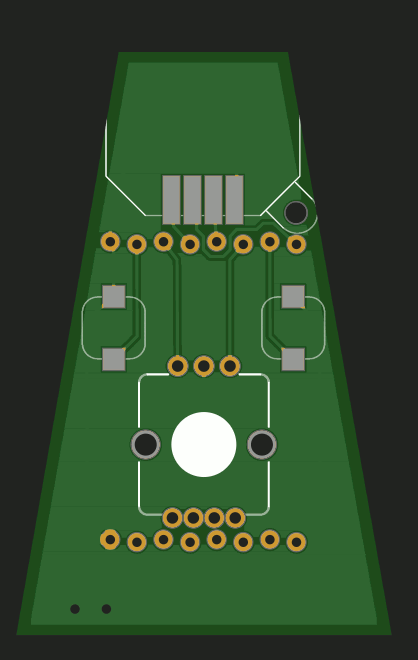
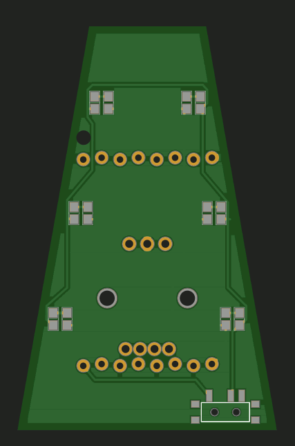
It’s simple enough: an encoder, a joystick, two buttons, and a bunch od LEDs on the underside, for backlight. I ran out of free pins for controlling the light, so I just put them on a physical switch instead (in retrospect, I should have also added a potentiometer for dimming).
The PCB is ordered, we will see how well that works when it arrives in a week or two.
3 Likes
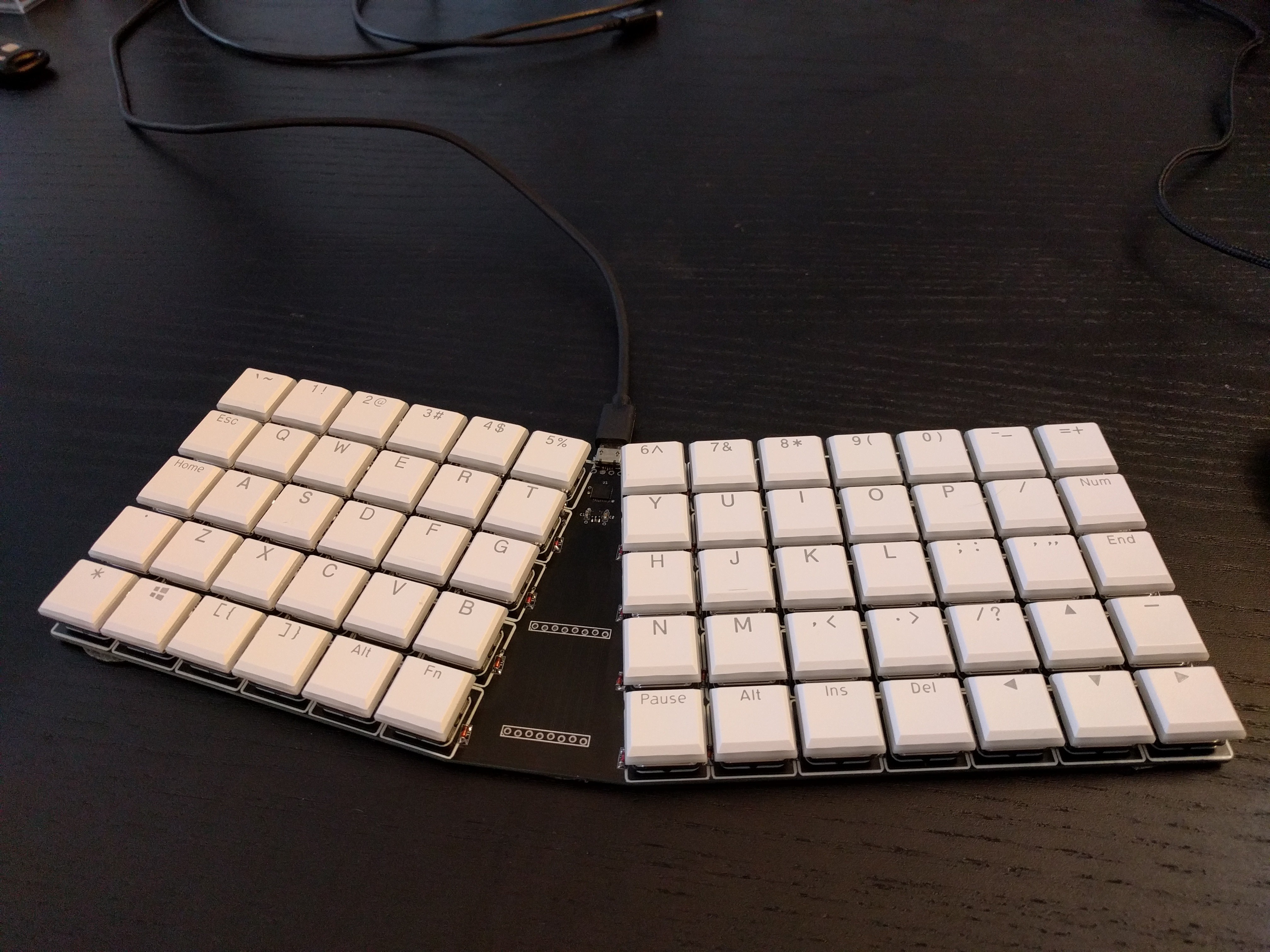
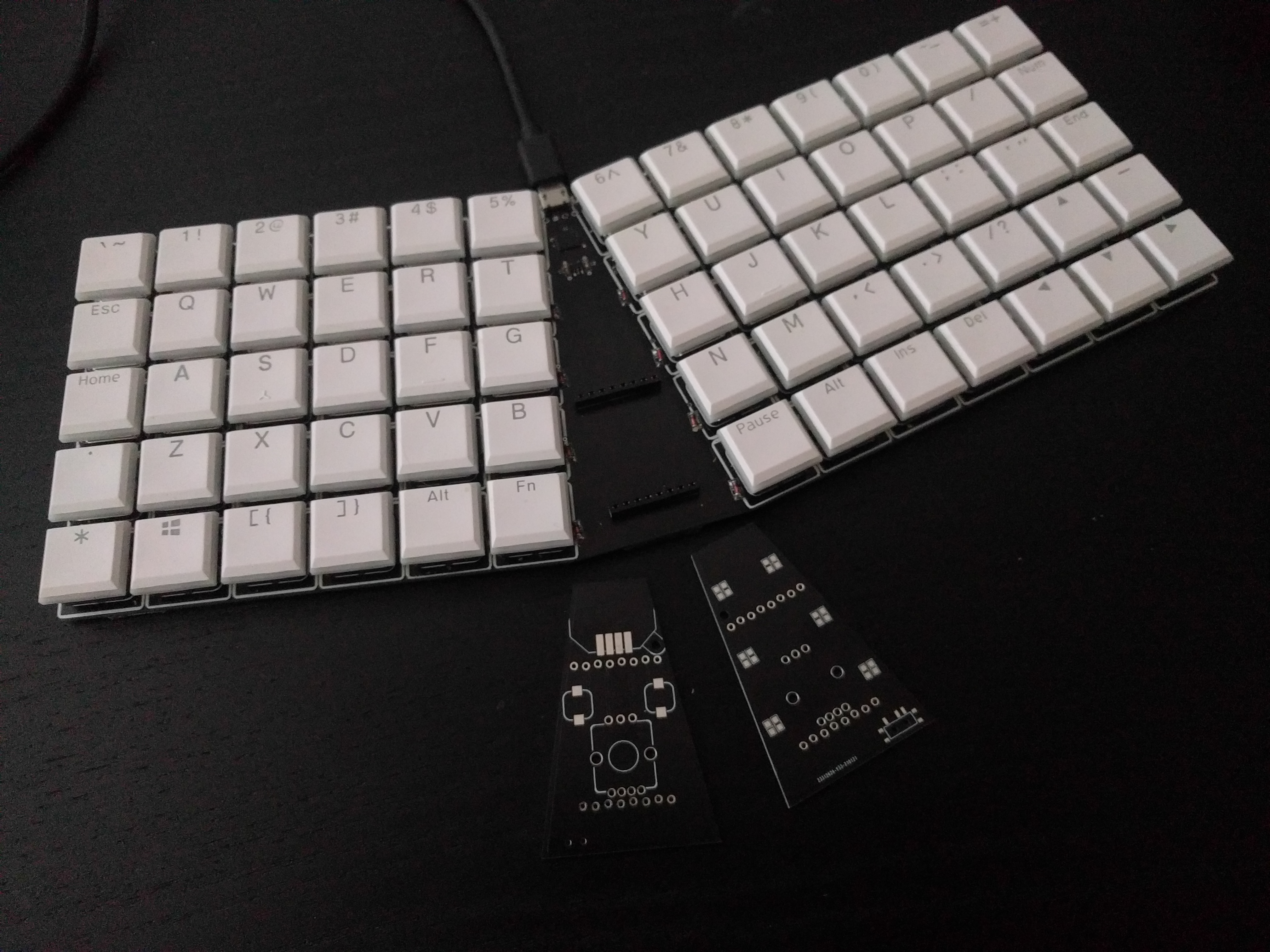
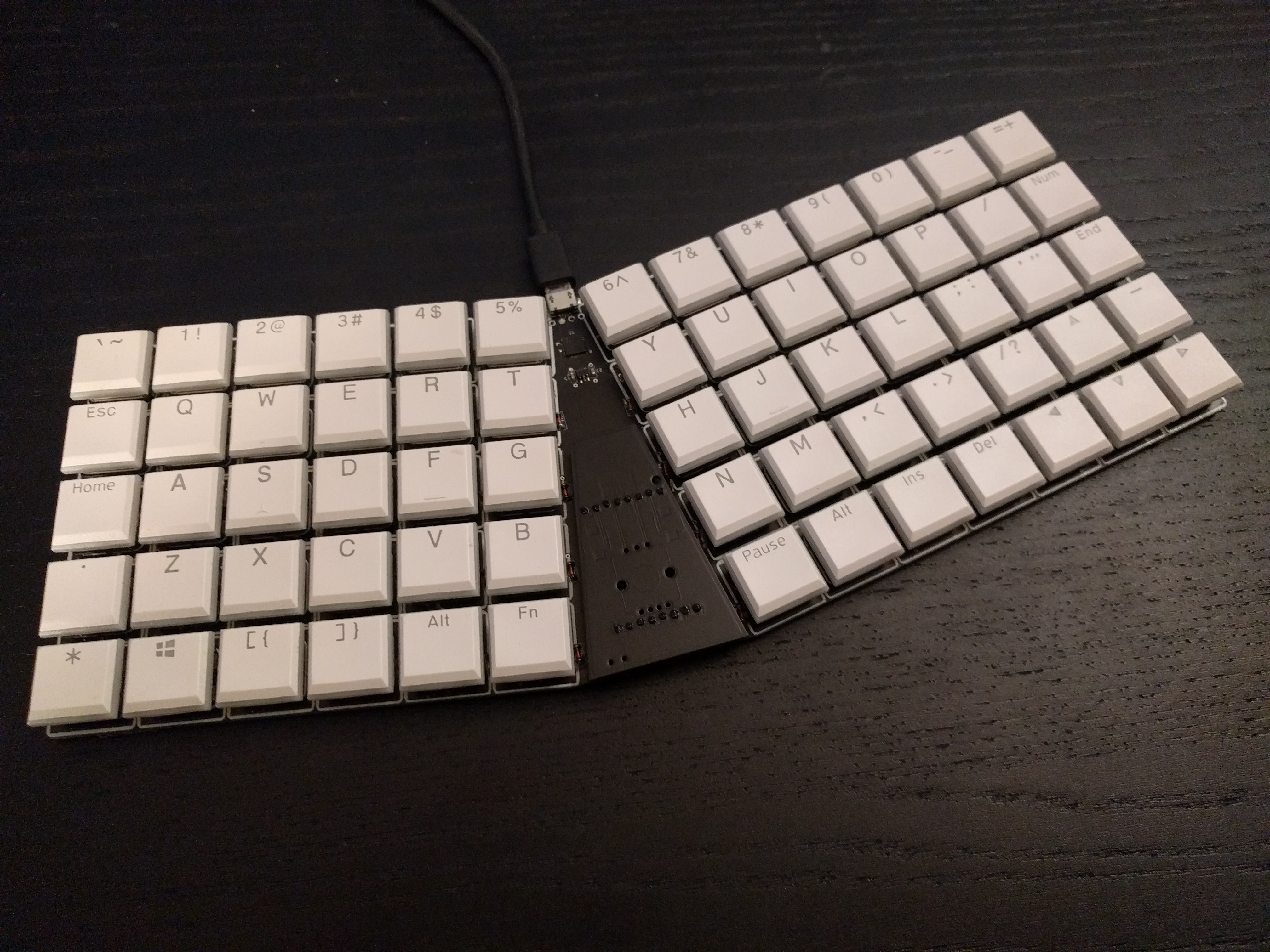
I also just realized that I never posted a photo of the finished final version of this keyboard, which I had been using all this time.
7 Likes
ohhh my god
is my end game you can share the files of the pcb and the settings in git hub or here?
i hate the keebs that have pro micro im gonna to build one of this (if you can share the files you help me) with a MBK keycaps and Red Pro swiches
I documented it at Kamina Keyboard | Hackaday.io and there are files to download there as well. Don’t hesitate to ask questions if I missed anything.
Note that programming the bootloader on the MCU is a bit of a chore.
If you are located in Europe, I have some spare PCBs that I can share.
The PCBs arrived a few days ago, but I didn’t have the time to post the photos. Here they are:
Here they are assembled:
And here they are with the light on:
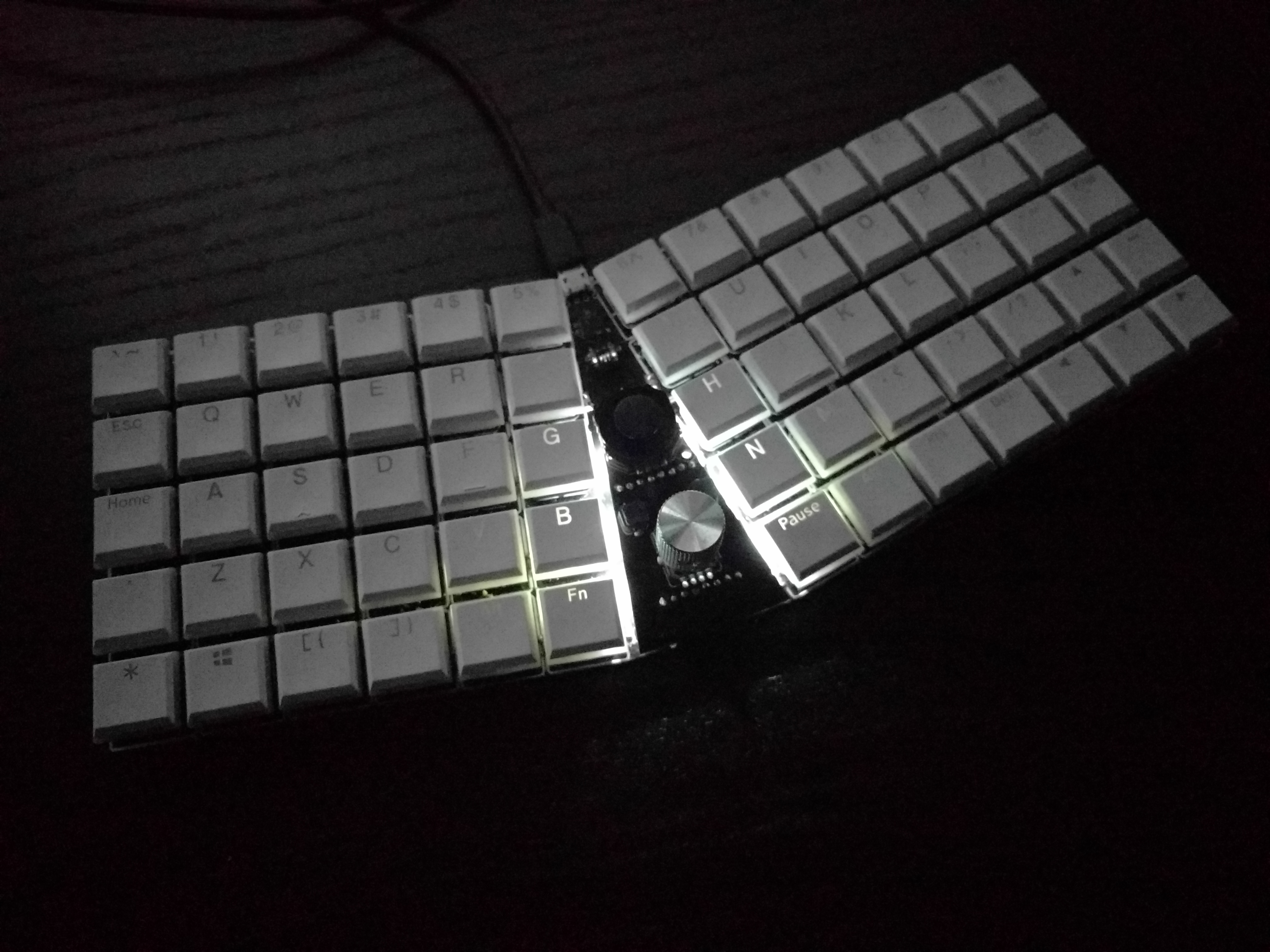
I admit the light looks worse than I hoped, I should have used side-facing LEDs. But they do help locating the keyboard in the dark, and I don’t need to see the keys.
I also assembled one of the PCBs with only headers, to act as a plug when no module is connected:
Now I found a tiny blackberry trackball module and an encoder with a horizontal roll, so I might make another module later on.
3 Likes
Great!
Is the encoder working ?
You got me here — I don’t know, because I didn’t write the code for it yet. CircuitPython has a dedicated built-in library for encoders that uses interrupts to catch the signals and does the math for you, so it should be easy, but I didn’t have the time yet to try it.
1 Like
Haha!
I’m not too worried, you look to know what you are doing and it should work nicely in the end
Damn, you sold me CircuitPytthon so well that I want to experiment with it in a future project !
@deshipu thank you for sharing your code, and your help. I started a little project that is coming along nicely. I was just wondering. Does it take about 20-25 seconds before typed characters start appearing for you once you plug the board in? It seems like some delay is expected, but the amount I’m seeing seems excessive.
edit:
I figured it out. It doesn’t seem to like being connected to a usb hub / switcher.
One thing I would suspect is your operating system writing something to the USB drive. CircuitPython will wait for the write to complete, and restart, assuming you changed the code. I work around this by compiling my own CIrcuitPython firmware without the MSC and CDC endpoints, leaving only HID — this way it also doesn’t clutter my devices list. Of course you have to upload and debug your code first, with regular firmware, and then switch to the custom one once you are happy with it.
There is work ongoing for supporting dynamic USB endpoints in CircuitPython, then I can make it so that you only get the USB drive and serial if you hold a certain key while connecting the keyboard, but it’s not ready yet.
1 Like
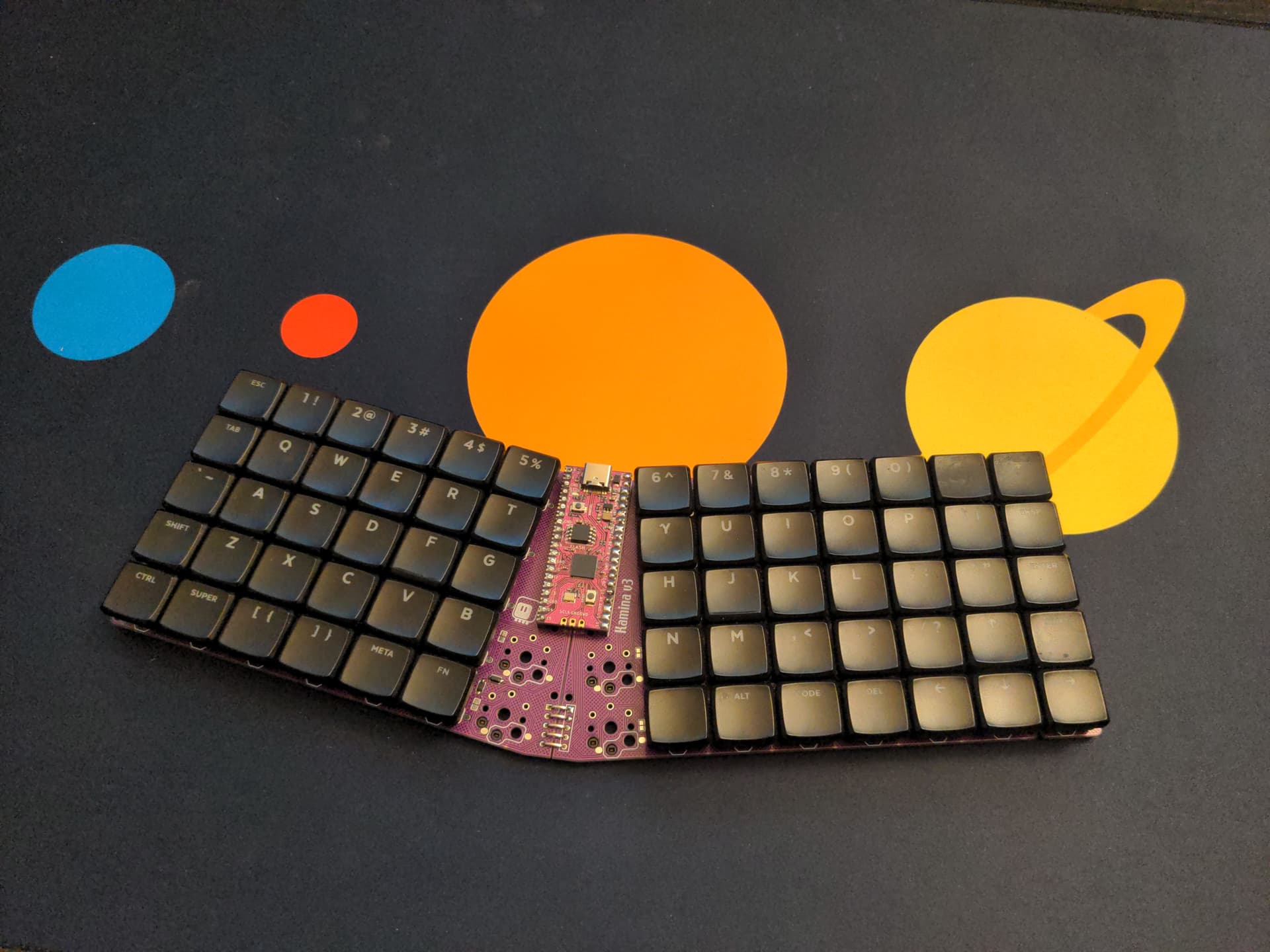
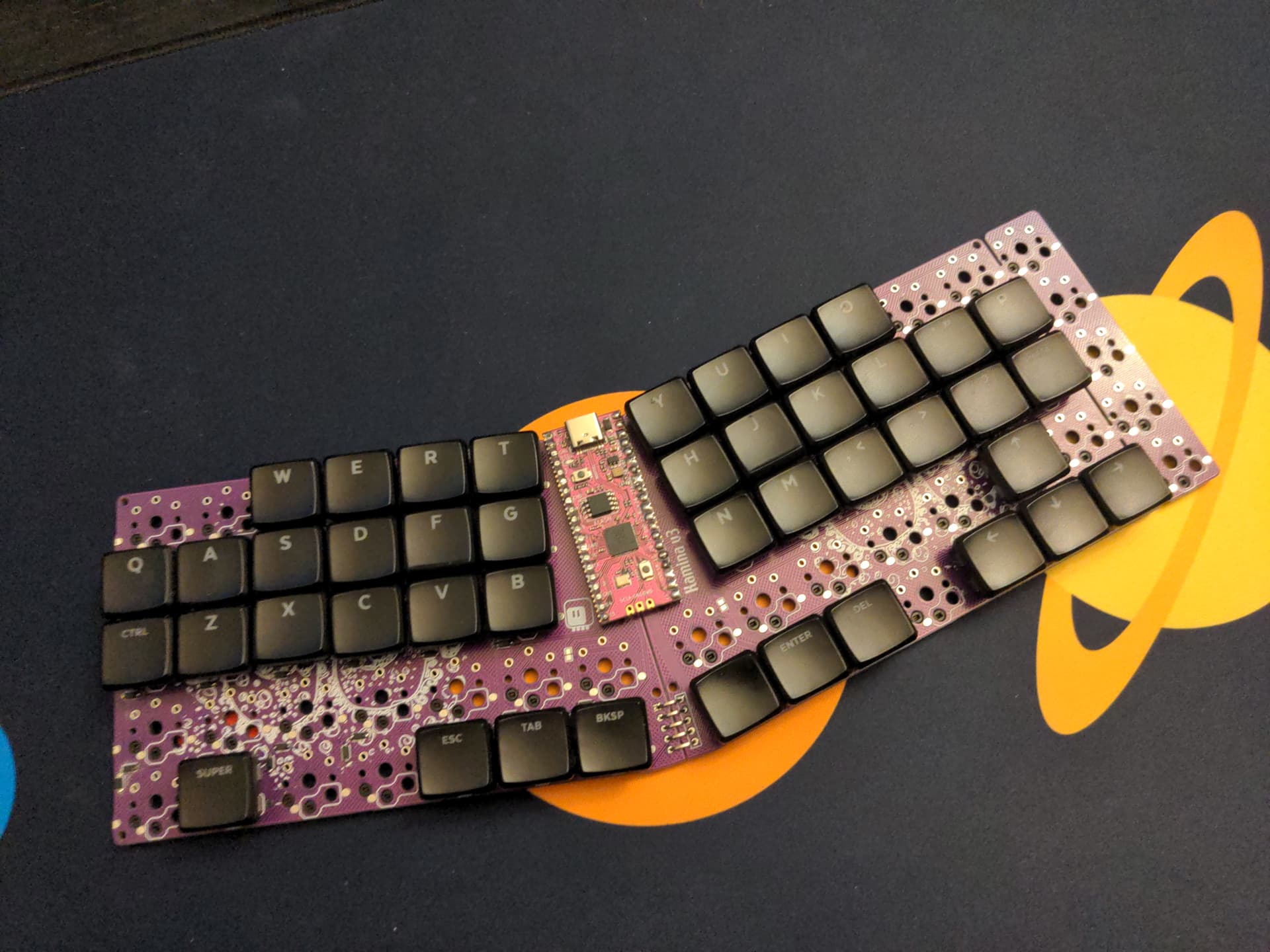
I have an update on this project. I just finished version 3 (actually 3.1, because of a small bodge).
There was a lot of interest in this particular keyboard layout, because it seems to strike a nice balance between a more traditional keyboard, and an actual ergonomic keyboard. It’s ortholinear and split, but still has most of the traditional keys on the default layer. It seems to attract people who are curious about ergonomic keyboards, but reluctant to take the plunge.
However, people who wanted to build this keyboard were scared off by the bare SAMD21 chip, soldering a QFN chip and flashing a bootloader on it using a special programmer and software. It’s not very beginner friendly.
So that’s where version 3.1 comes in: I’m using a raspberry pi pico development board on it (or anything compatible), so it’s easy to solder. You still have all those SMD diodes and hot-swap sockets, but they are not nearly as scary. And the PCB is now half as big and thus cheaper to make, because of the reversible design.
The last column can be broken off - mostly because the original had one more column on one side, but now you can also make it into a proper ergonomic keyboard by just breaking off those columns and rearranging the switches:
More information and the design files as usual at Kamina Keyboard | Hackaday.io
7 Likes