Making it my own

I’ve been buying and building keyboards for over a dozen years now. It seems crazy to me that I’ve never tried my hand at creating my own keyboard design.

The recent work of several talented creators on this very site inspire me daily to come up with something of my own.

I’ve got a lot to figure out since I don’t know any engineering software at all. I’ll need to figure out how to make both a PCB and a case.

My design tools for the past 20 years have primarily been photoshop and illustrator. I’ve played around a bit with sketchUp, but that’s the extent of my hands-on experience with 3d software.

What program can you recommend to learn for case design? FreeCAD? Fusion360? TinkerCAD? Something else? I have a lot of time on my hands and I’m willing to hunker down with a library of Youtube tutorials, but I would like to have a good idea of where to start that will work out the best for me in the end.

I see people using KiCad for PCB design. Is that the consensus?

Lastly, what do you think about a wooden CNC design to send off for milling? I would at least be able to finish the board myself (sanding and sealing). I wonder what the price of birch ply vs. raw aluminum would be. I’m assuming a large portion of the cost is simply for machining time.

IDK, maybe I want to get a router and just make something wooden by hand here. Not a lot of room in the garage, but it may be doable. :man_shrugging:

10 Likes

Have no fear, it looks FAR scarier than it really is when you’re starting out.

I highly recommend watching this video first - https://www.youtube.com/watch?v=7UXsD7nSfDY and then some of ScottoKeebs videos on YouTube where he walks through some of the basics of KiCad.

Case design is more of a “pick whichever is your favorite”, but if you don’t have a preference starting out, defaulting to Fusion360 is a good choice because it is fairly popular and used in a lot of other peoples’ work, which can help you if you get stuck. Warning - I found Fusion360 to be the most complicated part out of all of this stuff.

KiCad for PCB design is 100% the way to go. Super popular, lots of tutorials available, and a large community of people making footprints for things you’ll want like SOD-123 diodes, Nice!Nanos, etc.

I HIGHLY recommend pulling some repos of other peoples’ work to see how they achieved things and try to see what info you can glean from that as well after you get your bearings in KiCad. I will eventually get around to making my repos public for the Kinesis Advantage replacement board I worked on as well as maybe the replacement Klor PCB I made from scratch (debating on opening this one up because I had to modify the case to get it to fit properly due to the location of the reset switch).

One other piece you’ll need to think through is writing the firmware. This is another thing that sounds WAY scarier than it is if you’re unfamiliar with code, but the documentation for ZMK and QMK is spectacular and there are a billion projects out there to see how people wrote theirs, which can help steer you in the right direction.

Don’t get discouraged at all in this process! There are a lot of pieces to learn, but if you tackle them a piece at a time, it’s really not too bad. I am a software engineer for my day job, so the firmware stuff clicked pretty quickly, but I was able to go from 0 to having my first PCB in a little over a week. Now, I can spin up new PCB stuff in no time because I got really comfortable with the schematics editor in KiCad, which is a really important thing to use as you get more comfortable.

In short, don’t get discouraged. Give yourself small goals to hit that you can progress towards like deciding on the MCU you’ll base your project on, then working out how to make a schematic in KiCad, then populating the PCB editor from your schematic, then routing your matrix, etc.

Probably a good order to go in:

  1. Watch some of those videos I mentioned above to get a feel for what you’re in for.
  2. Download KiCad and setup your project.
  3. Complete your PCB design
  4. Start looking at how to write your firmware by consulting ZMK/QMK docs depending on what you choose as well as reading some repos from other peoples’ projects.
  5. Now start thinking on your case design
  6. Download Fusion360 and watch some tutorials
  7. Work through your case design and possibly tweak your PCB if it’s just not working out how you need it.

Good manufacturer for PCB stuff is JLCPCB for a cost effective approach that is widely used and pretty good quality.

Think that’s as much of a brain dump as I have at the moment and hopefully not too verbose to be useful! Enjoy the process, this stuff made the hobby fun again for me after being in it for the better part of a decade myself.

8 Likes

That’s really helpful! Thanks. :blush:

2 Likes

One could fairly argue that I’m still quite low on the skills curve for designing keyboards, but I thoroughly enjoy my little junkboards and use them almost exclusively. @TheNamesTy45 gives a good overview. I would just emphasize that there’s no one “right” way to do this as long as you end up with a device that you enjoy and feels reliable.

For KiCAD, follow some tutorials and remember that it has twin workflows: first the electrical schematic and then the physical layout. My own PCB was almost laughably primitive, but it worked on the first try and with a slight tweak to route the traces to through holes with a specific MCU in mind (instead of just a line for hand-wiring), it would begin to approach certain (low end) commercial offerings. I will say I didn’t find it particularly intuitive, but just follow step by step and find a “library” of switch footprints and it can come together very well. Fortunately, KiCAD is free and open source and I rarely see newbies directed to anything else. I second JLCPCB (tariffs pending), and they offer a nice discount o your first order.

Of course, hand-wiring is also an option. Joe Scotto has elevated matrix wiring to a kind of art form, but just using old Geekhack techniques, I don’t think I’ve had a single joint come loose in months, and back when I would get the occasional one, they were easy to fix. Just sayin’… :rofl:

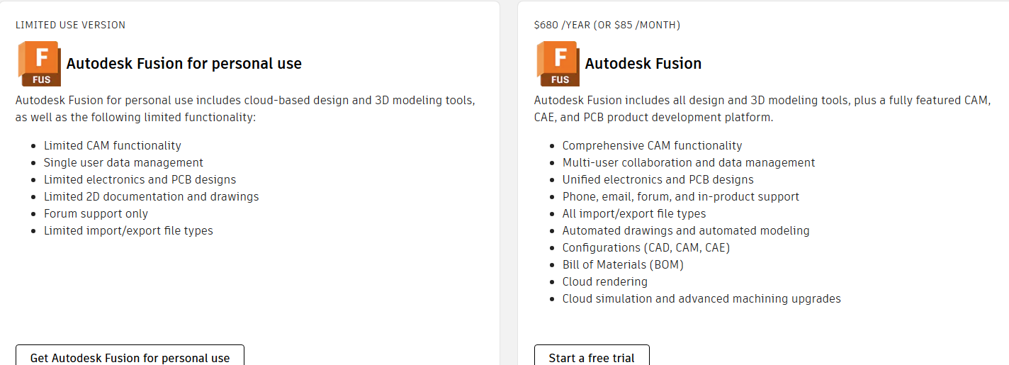
For CAD, Fusion is certainly an option. Autodesk is not the most hobbyist-friendly vendor, and they love to erode features in the free version, but they’re not the worst either, and the number of tutorials is VAST. I actually did a shallow but broad survey of consumer CAD software last year. I personally settled on a license for Alibre Design, but I’m impressed with FreeCAD’s progress of late, and many of the other options are good, especially if you have zero intention of trying to commericalize your work.

I actually did my very first board by designing the plate in TinkerCAD, and you can do some interesting things with it, but tempting as it is, I wouldn’t recommend it. Even something as simple as a fillet or chamfer has to be done as a manual action, and revisions can be a pain if you aren’t very careful in a way you’re likely to have learned by using one of the more sophisticated packages anyway. Sketchup is really poorly suited for CNC and 3D printing, as it doesn’t focus on making geometrically sound models, though they can be mended, that’s just an extra hassle.

With the “proper” Mechanical CAD suites, the important thing to remember is that the core paradigm is “sketch, then extrude (or cut).” They’ll all call it different things, and there are different tools for sweeps and the like, but the basic idea to wrap your head around it is that you do a 2D drawing, then tell the program to “make it this tall.” Then you do another 2D drawing (often on one of the faces of the solid you just generated), and then tell the program to either make that one stick out by X millimenters or to cut into the solid by X millimeters. Those actions stack on top of one another until you get where you need to be. Coming from TinkerCAD, it was hard for me to adjust from “make a block, then stick more blocks onto it.”

I haven’t done a true wooden board (yet), but I don’t think a wooden CNC project would be drastically less expensive than aluminum, though you could save by avoiding finishing processes. The largest portion of the project will still be setup and machine time, and that won’t change much. Wood also behaves drastically differently than aluminum, and I’ve always been suspicious of CNC’ing solid wood. Seems like we’re tempting the gods of wood-movement, and cheap Chinese cases seem to have a reputation for warping. Plywood will behave better, but even with Baltic Birch, you need to be sure you’re up for that specific striated look. I still intend to do an Alps build with a “traditionally jointed” case, which is a fancy way of saying I’m gonna make a glorified picture frame, LOL.

One final point is going to be your plate. Laser or some other CNC machining operation on sheet stock is likely your best option there, and the 3D CAD suites can usually handle that fine, but Illustrator may work too if you’re comfortable with it. I have found strokes are annoying to deal with in Inkscape, so I prefer a 2D CAD option, but I presume an experienced Illustrator user won’t have the same complaints. I had some aluminum plates cut by Xometry, and I found them to be reasonable for 2D work. 3D milling may be a different matter and will certainly be more expensive.

Firmware wise, I’ve been very pleased with KMK, especially with the POG application. I haven’t got my RP2040-based boards working in BIOS before a proper USB stack loads, but that’s my only significant complaint. I do want to dive into QMK though, but while I’m generally tech savvy, my training is in non-technical fields (the law and English literature, LOL).

Overall, though, if you design a working PCB, you’ve got a working keyboard. Keebs have one of the lowest barriers to entry for getting a DIY product that acts and feels like a commercial offering, and the caps go a long way towards making it look like one too. Go for it!!!

6 Likes

Thanks for the advice. Appreciate it :blush:

3 Likes

Go for it, even make your own DYI CNC machine to begin with.

It would be really fun if you could document the process in a blog or vlog. It might inspire other people to bring their own ideas to life. Good luck!

3 Likes

Like the others said, Fusion 360 + Kicad is the way to go.
Still I am curious about Freecad V1.0, may give it shot one day.

This takes a bit of time to learn everything but for someone smart enough there is nothing that you can’t learn :slight_smile:

I have used RP2040 MCU many times now and I do recommend it for PCB design.
You can look at my Github repositories for the Leyden Jar and the Phoenix Project No 1 to have a look at how I did it.

Can’t wait to see your first creation !!!

4 Likes

I can also cant recommend KiCad enough, the tutorial from Joe Scotto was my start on that journey. That was a really great start to get rid of that “fear” of the complexity of the matter. Layout wise, I really liked playing around with the Keyboard Layout editor and also use that to generate my plate files. Or at least the DXF to further build the plate from there in CAD.

For CAD, youre very good set up with Fusion, to mention them also there is also OnShape which I used for my case design and Solidworks, which has a Maker license. All a bit of a preference situation there imho.

For my first design I started with a external MCU as I wanted to avoid the additional cost of PCBA when not even kowing if this will work at all. Not sure though if that was really justified, as everything turned out just fine. Even creating the QMK from scratch was much less painful than I anticipated, the worst part for me really was the case design, as my CAD skills are just not there.

7 Likes

Is there any translation directly from a KLE layout to KiCad?
My biggest worry with DIY KiCad is having a key or a row off by a tiny bit–I feel like every project I do some measurement is off by just the right amount that it screws everything up lol.
Watched a couple JoeScotto videos and it looks like you can set a grid and reference point for all the switch footprints, but then I guess you have to manually offset from that ref for all the switches?
I feel like such an old dog trying to learn new tricks when it comes to design software I’m not familiar with…

2 Likes

I think there actually is a plugin for that, but I never tried that myself. I used switch footprints from the awesome marbastlib, and worked with exactly that grid from then on. As you have a box that indicates the whole unit, layout was extremely easy to build. For alternating options, I used the corresponding footprint and aligned it then with the next regular switch.

3 Likes

Yeah, I don’t remember which set of footprints I used, but they had outer bounding boxes based on 0.25u Cherry, so they stacked perfectly fine. I do think there are some tools to help integrate KiCAD and KLE, but I haven’t gone hunting.

3 Likes
8 Likes

To align key footprints in Kicad without any trouble I create a custom grid value that is a multiple of a 1u key, like 1/8 u. this way I (almost) never had to complain about misaligned keys in my designs.

To have a good database of footprints I can’t recommend Gondolidrim Acheron lbrary enough, this is what he uses for his own design and the quality is perfect.
He does not have RP2040 footprints or symbols, but you can take those from my own library in the Phoenix Project No1 Github project (open source).

4 Likes

Finally got around to making a new public repo from my private draft repo for the Rasgueado KA2 replacement controller + thumb PCBs + thumb plates.

Just adding this as something you can reference as needed as you get deeper into KiCad / ZMK firmware.

5 Likes

I appreciate the links and discussion. It will take me some time to get up to speed but I’ll likely be back with questions.

5 Likes

Making a PCB is far beyond my knowledge but I personally use Fusion360, it has a personal license you can use free (and IIRC has most important features).
Solidworks is the industry standard in engineering at least where I’m from, if you can get a free license I’d recommend learning it but I don’t think they offer that.

I personally use Fusion360 and it’s great, there’s a learning curve but its well worth it, I don’t think it would be too different from SW.
I would not recommend TinkerCad especially for creating something as complicated as a keyboard case.

3 Likes

I was looking at downloading Fusion360 this morning so I could dive into some tutorials.

So the free (“limited use”) version will be sufficient?

4 Likes

I’m not an expert but I don’t see why it will not be sufficient enough, unless case design requiers special features or simulations that I’m unaware of, I think it would be more than enough.

I’m using the personal license and design cases/plates (for personall use) or generally just 3D models for my 3D printer and so far haven’t come across any issues or limitations for my usage.

You could try asking the businesses you’re thinking about using about what file types they accept and see if Fusion360 offer it in the personal license.

2 Likes

The free should be fine. You’ll need to juggle “active” projects in the Cloud storage if this becomes something you do a lot, but you can still back up to your hard drive. The CAM stuff is only important if you wanted to use Fusion directly with your own CNC device, and removal of it was a sore spot for some free users, but most people will still be fine with the resulting STP or STEP files that you can export. They can be converted to GCode for printers or CNC’s in stand-alone programs. The PCB will not be a major issue if you’ll be using KiCAD.

The other thing is that if you sell a few boards, you could theoretically hit their free-user revenue cap pretty quickly ($1000/yr). If you do, it would be worthwhile to plow some of those sales into a year of subscription, as the CAD vendors have very mature compliance departments.

Solidworks, mentioned above, is more commonly found in small to medium business, and their Maker Edition is very reasonably priced (something like $100/yr, with discounts readily available online). It has a $2,000/yr profit cap, which is a good bit more flexible, BUT should you exceed that, getting compliant would be much pricier.

4 Likes

The free Fusion version is more than fine imho, for the 10 projects you don’t need anything more than set the projects you don’t currently work on to read only. You can switch back and forth however you want, anything but a limitation for me.

Solidworks is even on a discount right now for 24$/year. DIY CAD Design Software (Personal Use) | SOLIDWORKS for Makers

2 Likes