Playing with Rotary Encoders - Coaxial/Concentric

Sup, I’m donutcat and I need no introduction.

Tl:dr: While I was on hiatus for dealing with GB backlog and personal issues during the late 2018/most of 2019, suddenly people started putting rotary encoders on boards. I built a BDN9 for someone(lovely little macropad) with a couple on there and I was all “these are cool and I’d do many things with them”, and started poking my nose into what they are, how they work, and how to shove them into things.

Those of you I grabbed burritos with after the Greenville meetup we talked about this specific idea, and I haven’t been able to progress on it until someone posted a super helpful link in the mechkeys discord for me. I’ll explain out my idea in a few steps:

First step:
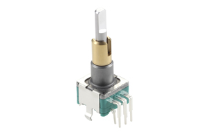
This Alps EC11EBB is what’s commonly referred to as a “dual concentric” encoder. Basically two encoders in the same footprint aside from only getting one push-button input. Seems like a lot of people use them for flight sims. Neat because you get twice the spinny bits per do-dinger.

Second step:
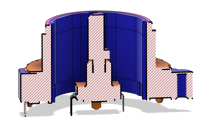
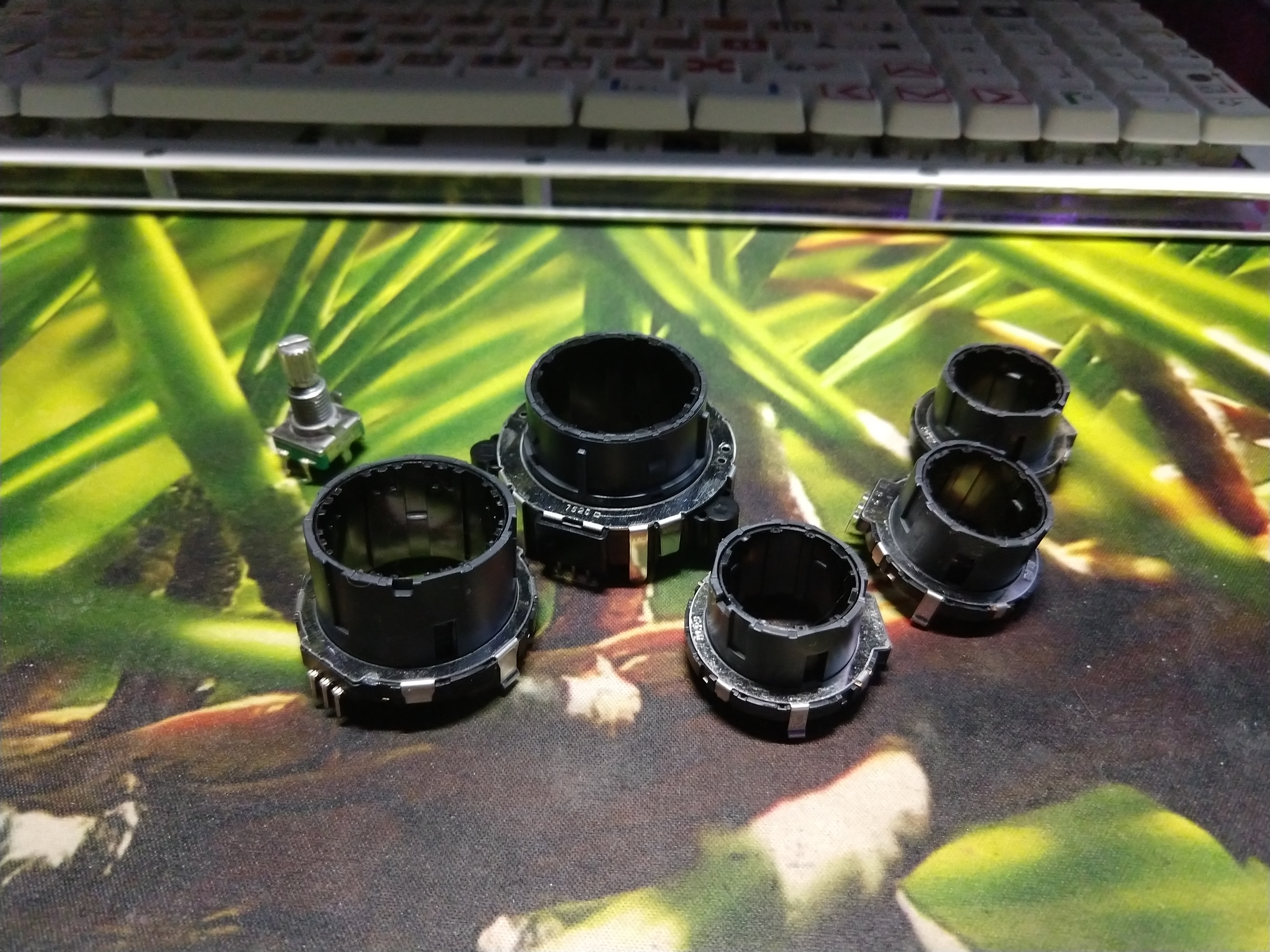
Your typical Alps EC11 encoder sitting inside one of their “ring” encoder models, the EC40A. Basically serves the same purpose as the EC11EBB above, it’s just more accessible to work on and a key point is that you can fit stuff inside the outer one, like say some wires and stuff.

Third step:
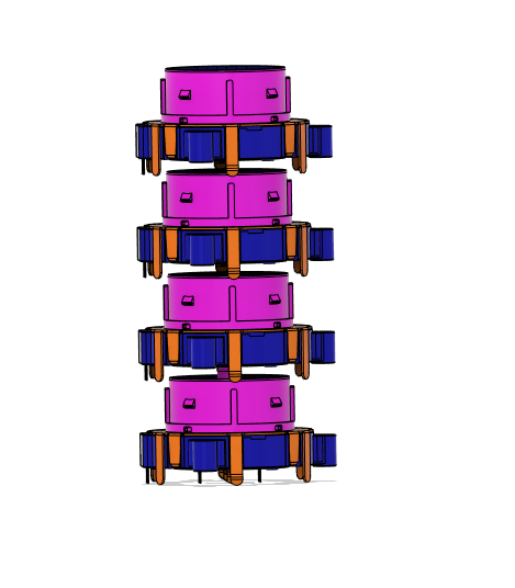

[Joke here about escalating quickly]
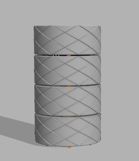
And here’s the point I’m at right now: stacking. If two encoders in one axis is so much fun, why not take it further? I’ve got some pieces drawn up to basically let me make modular “units” out of each EC40 w/PCB and stack them together as long as I’ve got the pins to drive them. For reference, each ring there is 55mm OD and 23mm tall with 24mm spacing between the units.

My personal use use for this is I’ve always wanted a little turn-y wheel for my volume control, plus I’ve been playing with nircmd lately and I’m wanting to use that to control app-specific volume across a few things like Spotify, Firefox, Discord, and whatever games I have going at that moment.

One thing I’m thinking of doing is setting up the “core” structure of the column so that it could be mounted horizontally on a mount and used sorta like a giant row of scroll wheels. Removes the ability to have a central EC11 for a pushbutton but gives increased stability and potentially more accessibility.

I figure now while I’m waiting for parts to come in for testing is the time for a little feedback on my endeavor here. I’m thinking of making this it’s own device with various size configs, running it off QMK and maybe at some point doing a GB for them if there’s interest at all outside of my own. Let me know what you’re thinking and I’ll hopefully have some irl pics of my attempts. Something I’m not really sure about is the sizing of the wheels. Single wheel devices all seem to go for the big, easy to grab wheel, but I’m not sure if that’s the right look/feel to go to for multiples together.
6 Likes

Making a comment on my own post because I feel the discussion of the software side of this project warrants this separation.

Per the post, I’m planning to power this on QMK because that makes sense; QMK allows easy mapping and customization, has a lot of options for extras goodies like RGB(which everything needs), and it’s just overall good. One limitation to this is the nature of the software side of encoders(the ones we use anyway) needing to pull from Ground(normally) since reading them is just reading the order in which the two other pins are pulled low.

Incremental encoder - Wikipedia Here’s the link on incremental encoders that explains it. Tl:dr, square waves and grey code.

This means that currently you have to devote two IO pins to each encoder(just the spinny bit, SPST portion takes one too) which quickly eats up your available pins. On your average ProMicro you’ve got(last I checked) 18 IO to work with meaning a max of 9 encoders off it. This is probably enough for most people, but I do silly things(look:ScrabblePad) and I’d like more encoder for my IO. Plus I’d like to minimize how many wires I’d need to snake up through my leaning towers of encoders.

There is currently a PR sitting on the QMK Github for more easily using encoders in the “normal” switch matrix (Adds Encoder Matrix Functionality by jackhumbert · Pull Request #7209 · qmk/qmk_firmware · GitHub) courtesy of the main man Humbert himself. Unfortunately, it’s sitting in PR purgatory from apparently an AVR incompatibility and some build failure that I don’t know how to read. I’ve gone through the effort of setting up msys2 on my Windows install(an affair to be sure) so I can now mess about with sticking my own firmwares together and I’ll be trying to shoehorn this new feature in and see if it magically works for me.

Along with that I’ve also got a couple other ideas to try doing things incorrectly enough that they do what I want. Feedback and advice on this portion is also much appreciated.

5 Likes

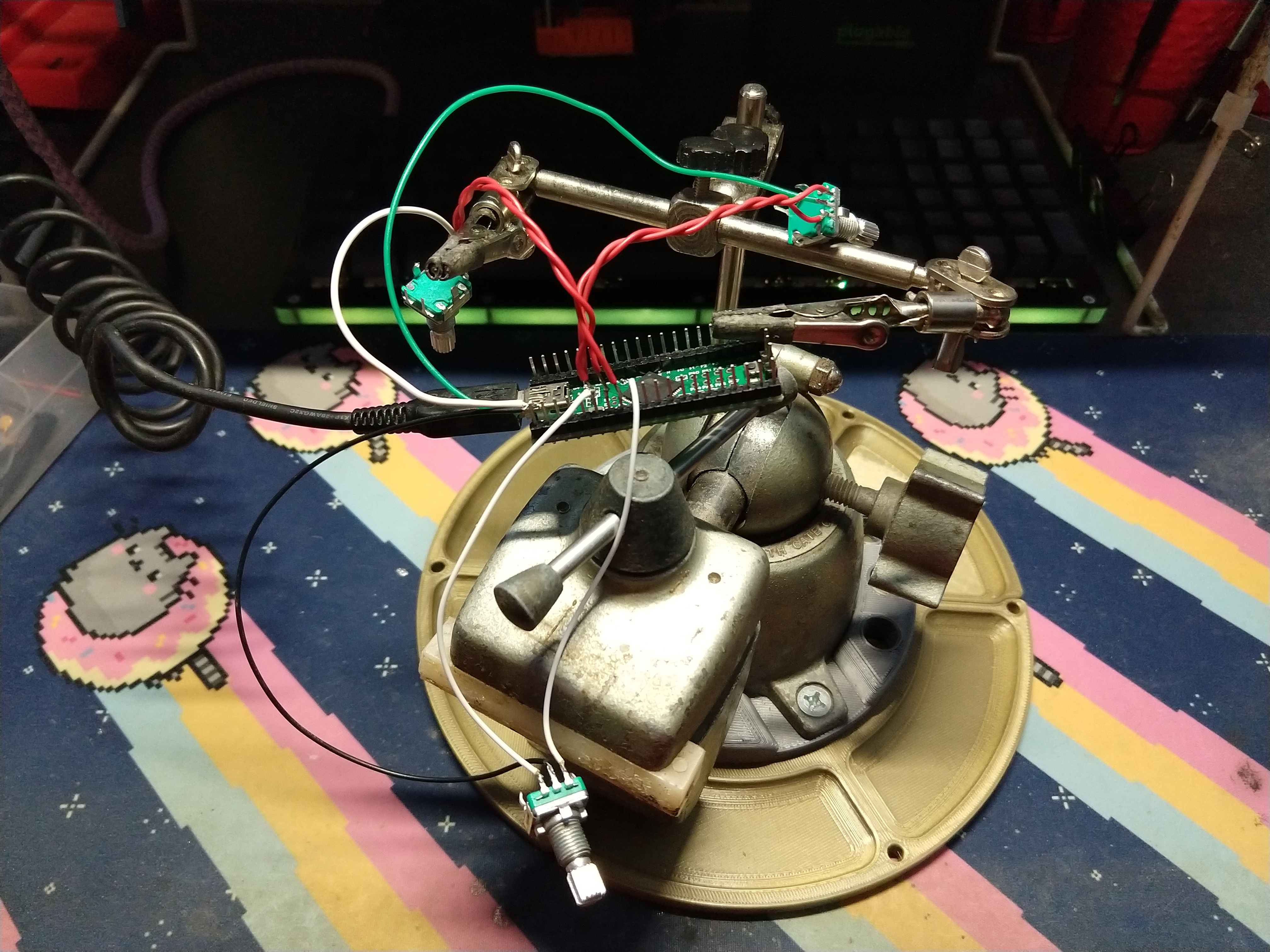
Little update because I got some EC11s in to play with for the software side of things since they’re like 1/4 the price of the ring EC series.


Delightfully chaotic testing setup. Notice that I’ve got one signal wire for all three encoders going to the same pin on the controller. My hypothesis was that since the state data for determining which direction an encoder spins should include both the IO inputs involved, it should mean that for example D3+D4 can be differentiated from D3+D5 as different encoders.

So far in my simple testing with three running off the same pin for A input this has worked. In just using them one at a time there’s not crossover or missed/incorrect inputs registered. I imagine that using two concurrently off the same row/column may result in crossed inputs, but this could possibly be resolved with debounce adjustment and tactical diode placement. In a way the downsides are similar to Charlieplexing as used in switch matrices.

I’m quite happy with these results as it means getting many more encoders from the same IO, even on AVR controllers that aren’t able to utilize Humbert’s experimental C pin define code.

4 Likes

Sorta small update, I’ve posted in other places about my 3x3 encoder array I finished up
https://imgur.com/a/9LnSZaP

It’s running the matrix layout I proposed and so far is working fine aside from my own issues hand-wiring inside a small space. Having the option of matrix wiring greatly expands config options for stacking version since it’ll increase max stack size and reduce the number of wires that need to run up through the modules.

Next step is getting my hands on some of the ring encoders I’m looking to use for PCB and structure prototyping, as well as trying a little something new that I think would be a neat addition to the functionality.

1 Like

Got some samples in to play with. Something I wasn’t prepared for is how dampened the tactility on the ring encoders is vs a normal EC11. Definitely loses some of the clean click that the standard one has, though maybe that could be changed if someone got brave and popped one open to replace the stock lube with something thinner or a dry lube.

3 Likes

Been a hot minute, aint it? Been fiddling with the bigger encoders here lately and decided to document it.

After my Fusion stream today this is what I’ve got, a switch that sits inside the encoder.

My plan was trying to wrap it into a silly replacement for a single EC11, a bigger encoder with 3x the customization options by adding your own switch and cap to the top, but unfortunately it looks kinda fucking dumb. Someone said to make the wheel smaller, but it’s already a couple mm shy of not covering the frame of the encoder, so that’s not super an option.

I’m thinking now my option might just be recess the switch entirely and have it with a printed cap that normally is flush with the top surface. Still lets a user have their own switch involved, but locks in the aesthetic.

5 Likes