Hello All,
I could not find any information about the internals of the Bluetooth R3 keyboard online so decided to make this post/document to share my findings. I mostly wanted to know if a Bluetooth R3 could be used in a Norbaforce case, unfortunately the Bluetooth R3 will not fit in a Norbaforce case (without some heavy modifications/custom breakout PCB).
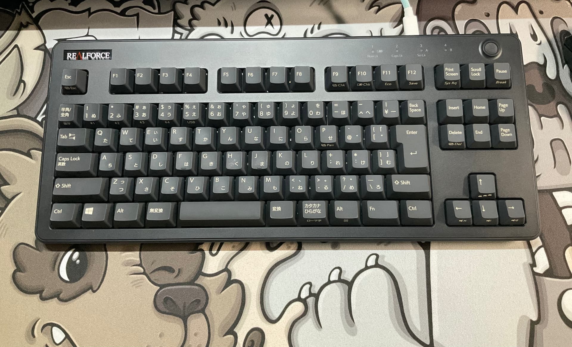
This document goes over the disassembly process on a Realforce Round 3 Bluetooth JIS layout (R3HC31) and ANSI version (R3HD21). Thank you to @optimusg for providing photos of the ANSI layout Bluetooth R3 (R3HD21)
DISCLAIMER
I AM NOT RESPONSIBLE FOR ANY DAMAGES THAT MAY BE CAUSED FROM DISASSEMBLY. THIS IS NOT A GUIDE BUT IS AN INFORMATIVE DOCUMENT. READER ASSUMES ALL RESPONSIBILITY FOR ANY DAMAGES. THIS WILL VOID YOUR WARRANTY
First you will want to remove the top layer, this can be done with a plastic spudger to avoid any scratches. It is held in with clips.
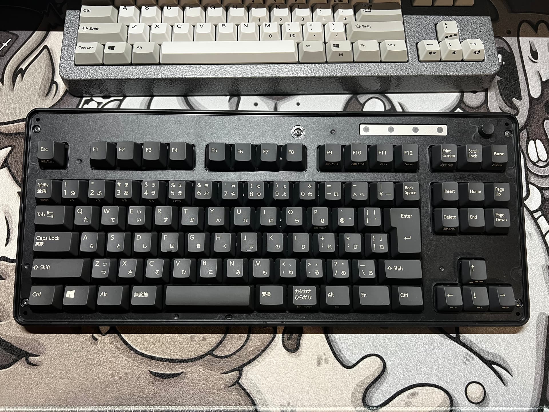
Next, remove all 5 top screws. The top middle one will be under a warranty void sticker. Then you can remove the plastic top plate and Bluetooth button.
Please note this will void your warranty.
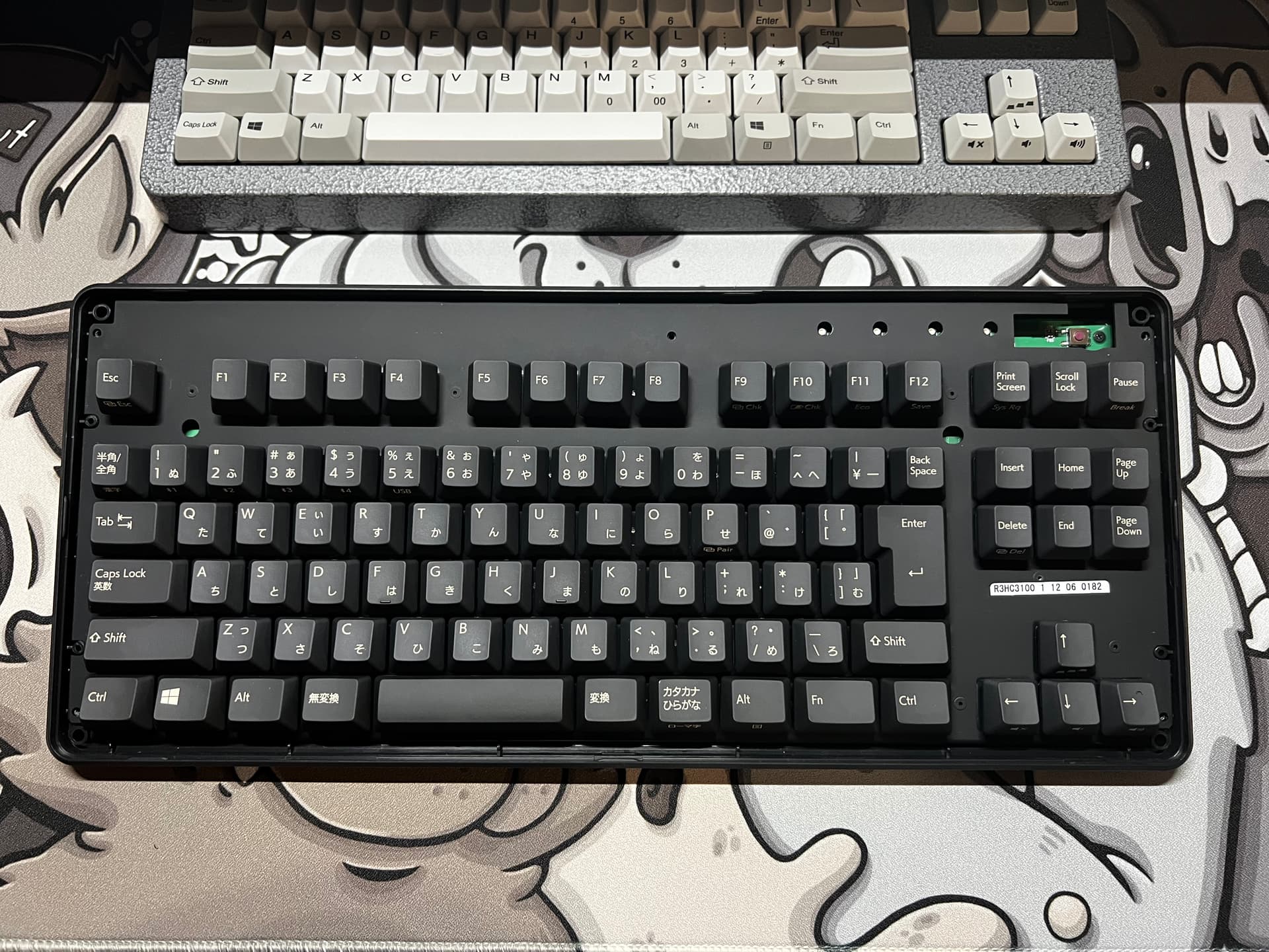
The actual plate will now be free.
This differs from the older Realforce boards as it is disassembled from the top down.
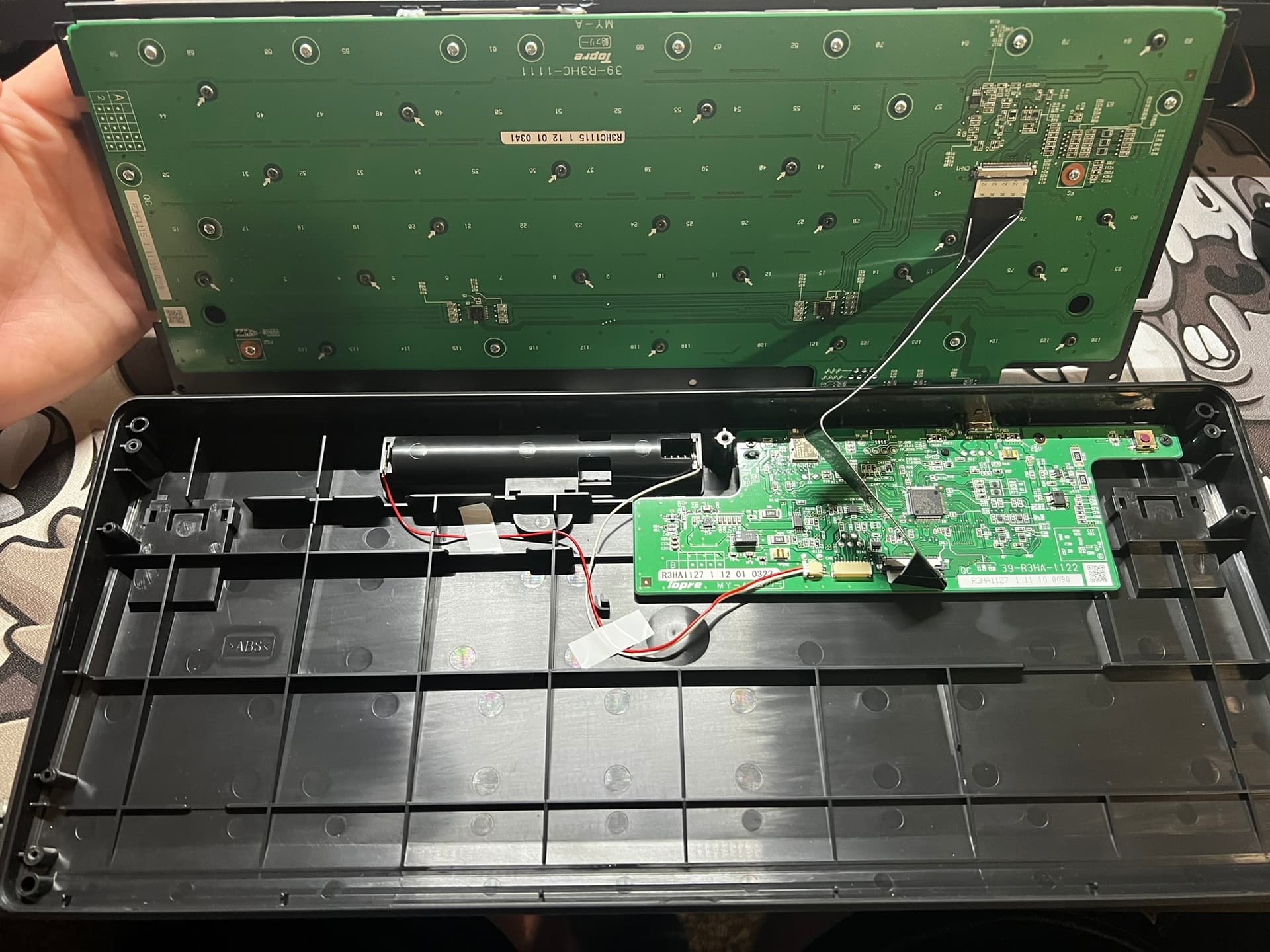
You can now lift up the actual plate and PCB assembly from the case. Please be cautious when doing this step as the ribbon cable will be attached.
To remove the ribbon cable, gently pull down on the cable from the PCB connector and it will come out. This model does not have any locks or push tabs that clamp the cable to the connector so it is just a push/pull.
Please note, this may not be the same mechanism in all the R3 boards. If something is stuck, DO NOT force it!
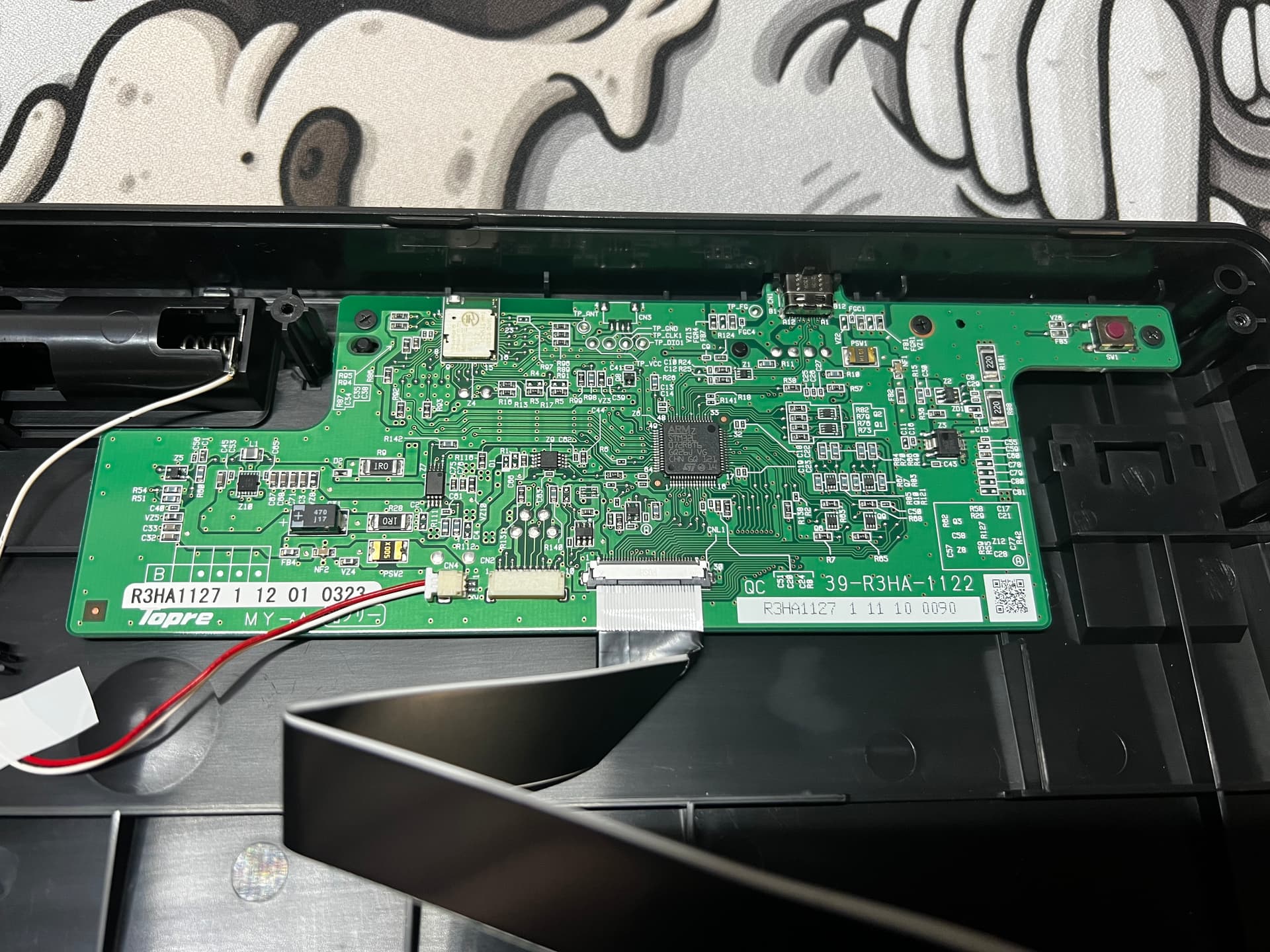
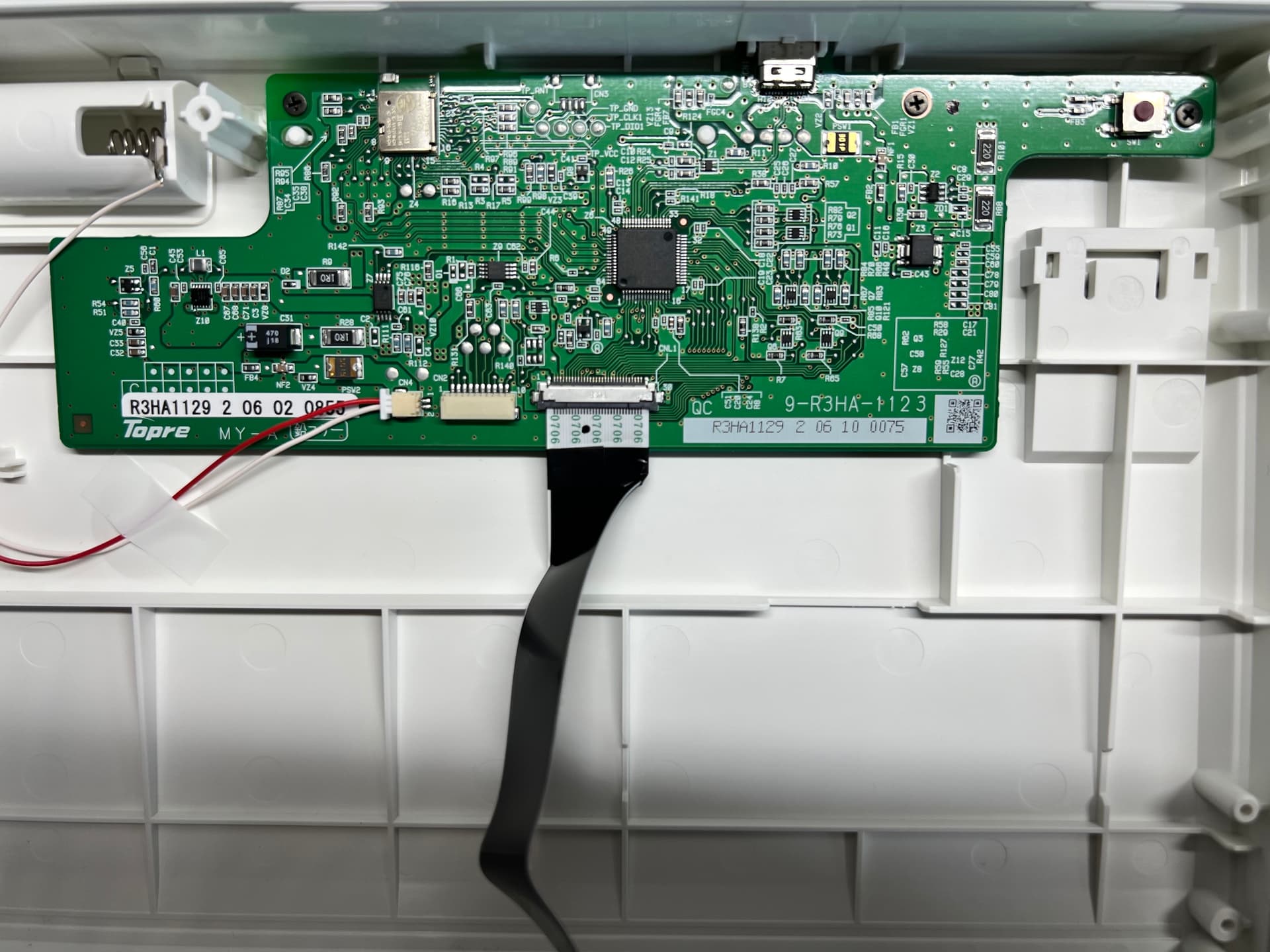
Close up picture of the breakout board. This is the same board layout in the ANSI Bluetooth keyboard as seen in the second photo.

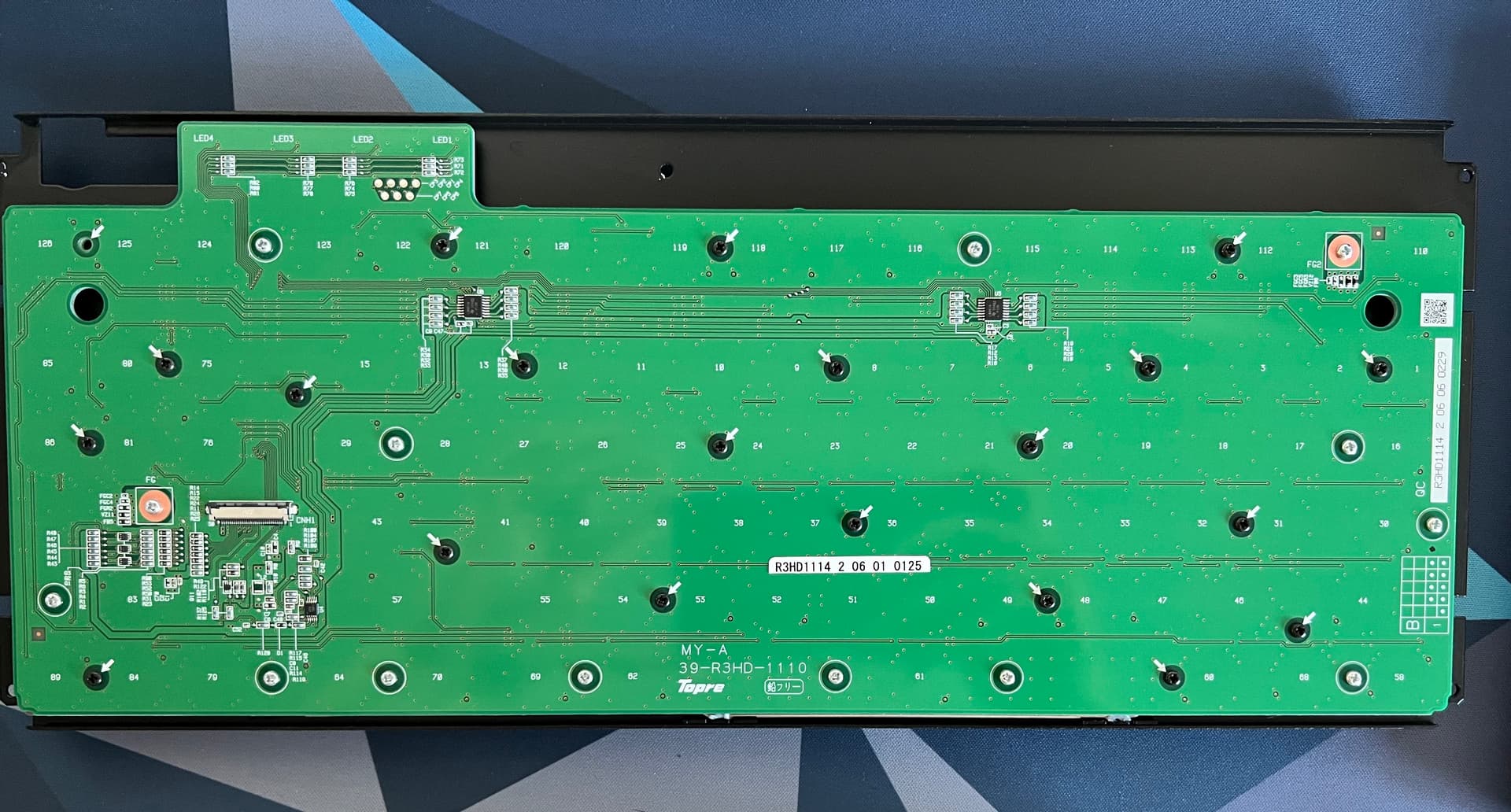
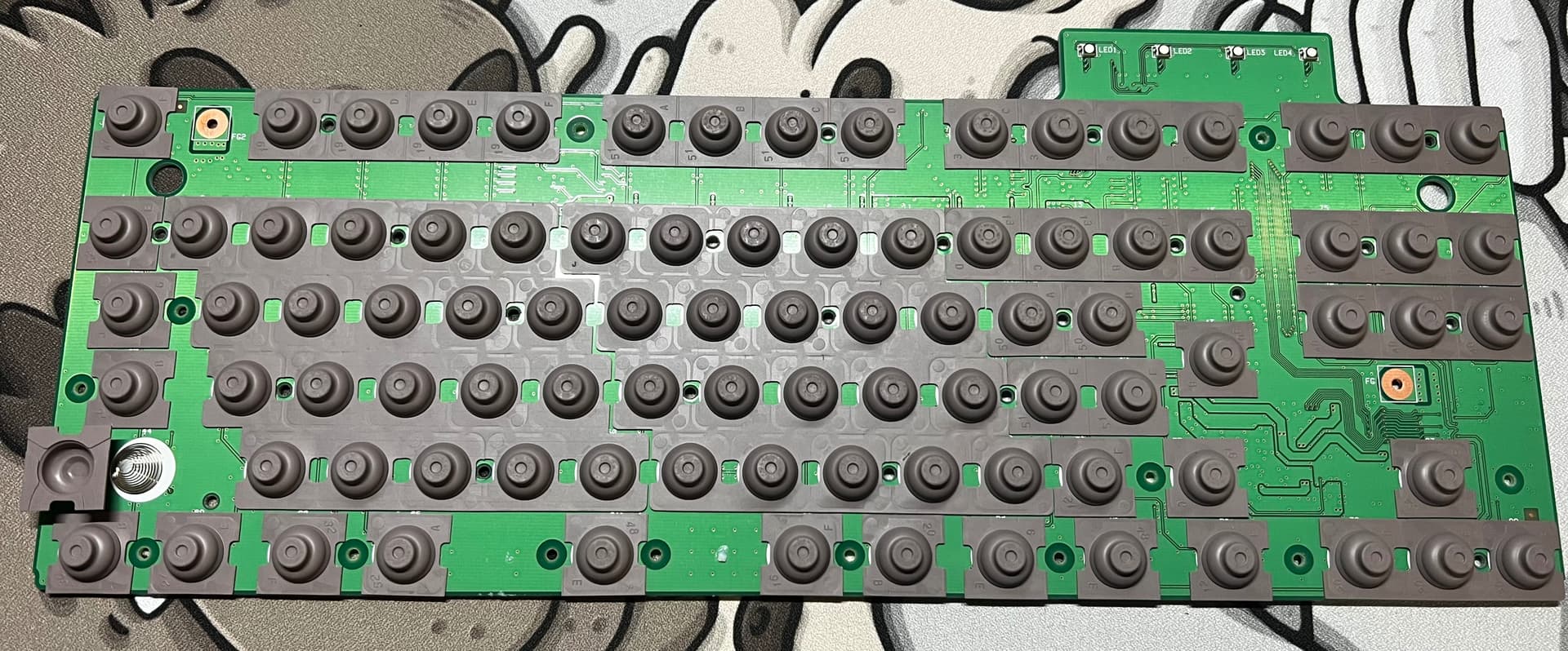
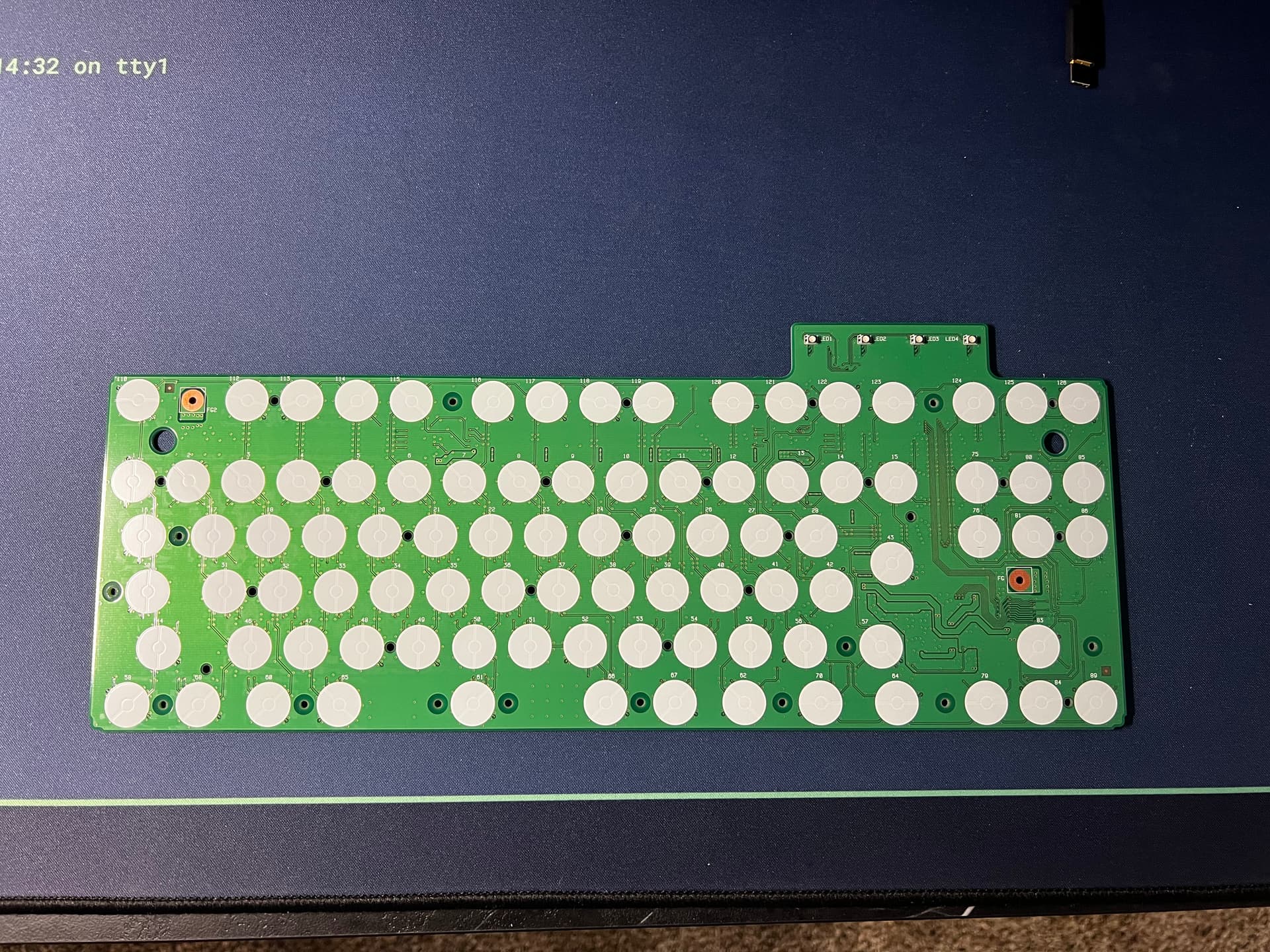
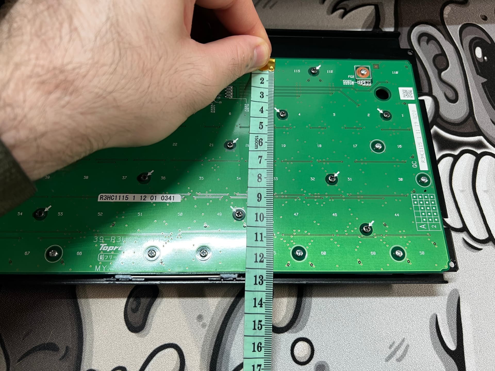
Picture of the bottom of the PCB. This is a different design from the past Realforce boards. The LED lights are on a protruding part of the PCB at the top. From here you can remove all of the screws to remove the PCB from the plate/sliders. ANSI version also has the same PCB layout (minus different traces for the different layout keys) as seen in second photo.
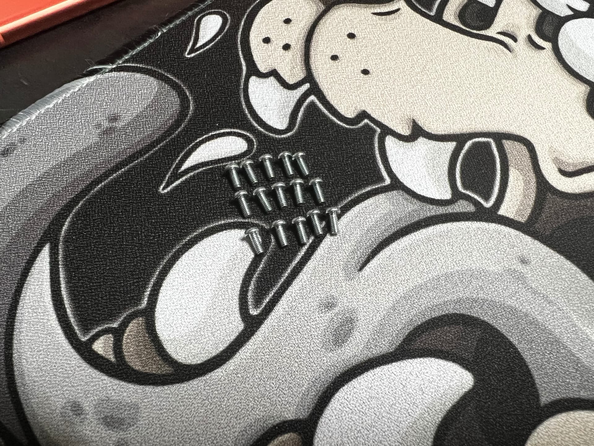
Total of 15 silver screws that come from the “Circle” holes on the PCB.
Please note, you must put the “Circle” screws back in their respective holes or you may risk damage to your PCB/Plate.
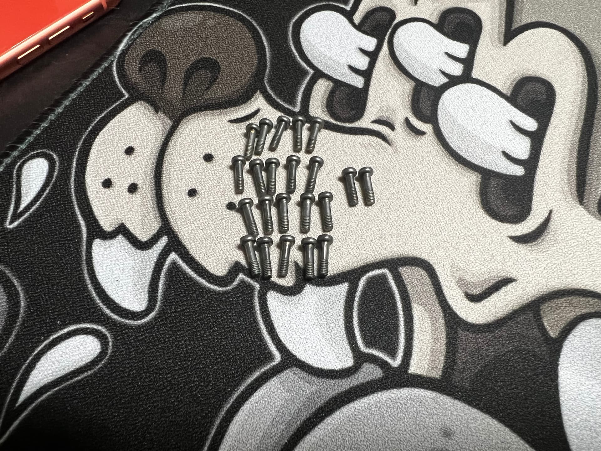
Total of 22 black/gray screws that come from the “Arrow” holes on the PCB.
Please note, you must put the “Arrow” screws back in their respective holes or you may risk damage to your PCB/Plate.
When removing the PCB from the plate/sliders for the first time it may have some resistance, this is normal. Take your time to slowly remove the PCB, you should not have to pull very hard. It feels like it is lightly adhered to the plate.
If you are unable to separate by pulling lightly, please check and ensure you have removed all screws from the back. There are no screws on the front of the plate.
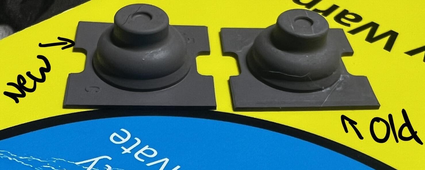
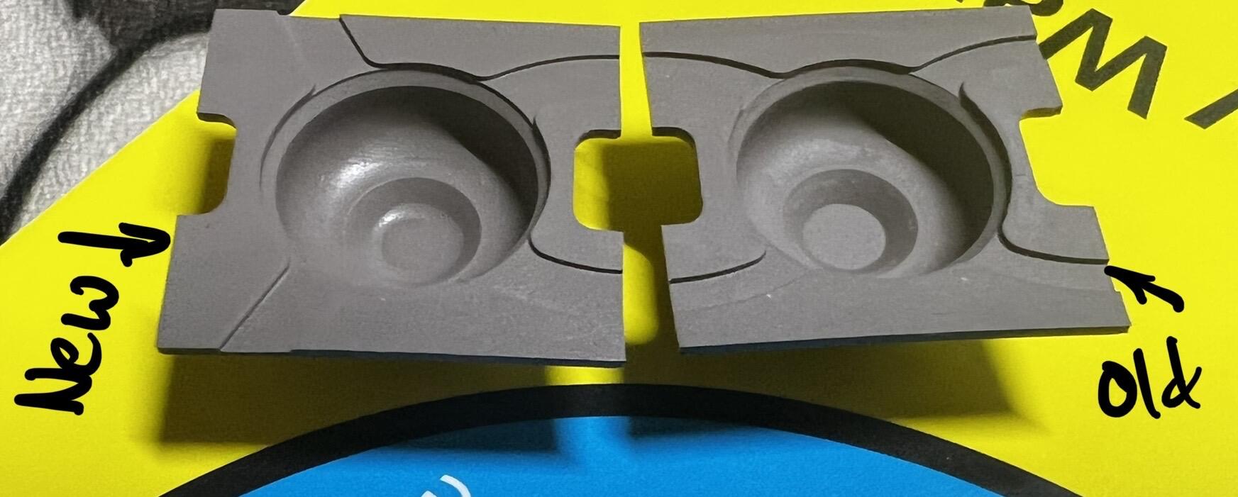
The above pictures are showing the new domes vs a R2 keyboard’s domes. From what I can see they are exactly the same material and weight.
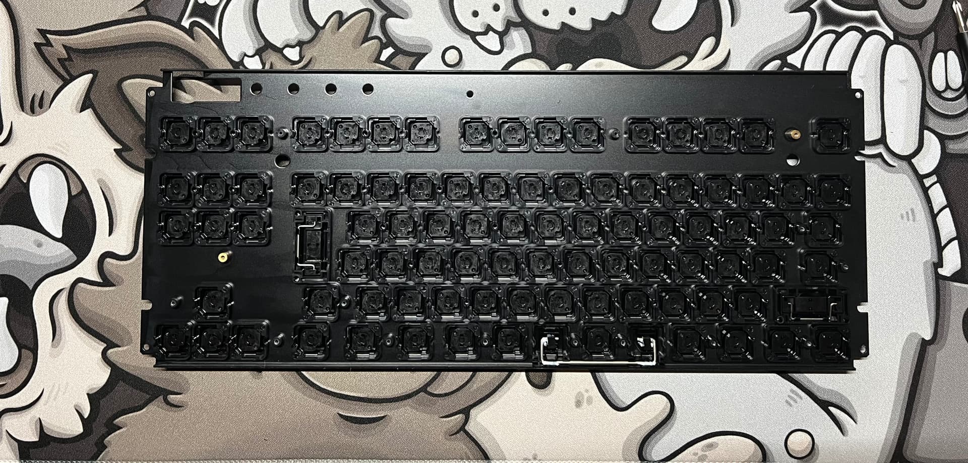
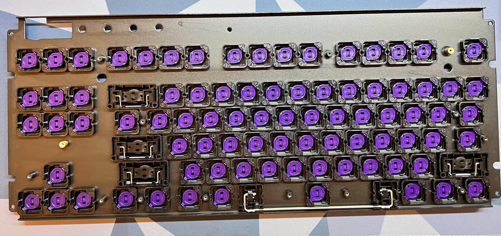
Picture of the bottom of the plate. It is a different design from the previous versions, but still metal. The plate shape is the same in the ANSI layout as well as seen in the second picture.
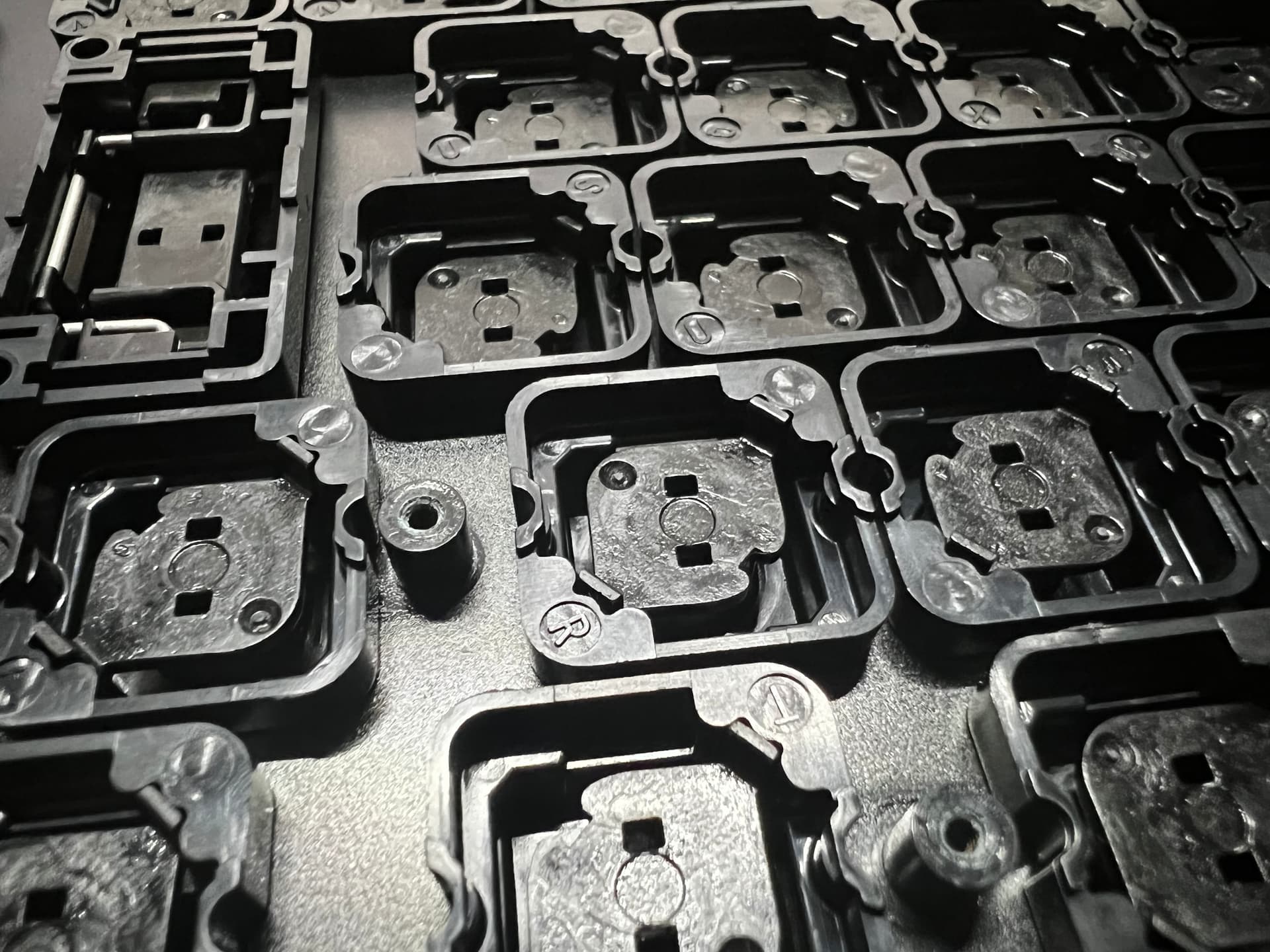
Sliders are factory lubed it seems. The spacebar stabilizer is lubed as well, the other stabilizers are not (enter, and left shift).
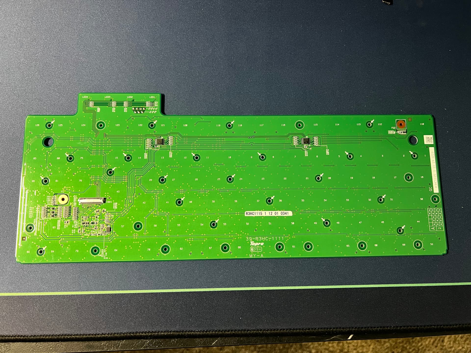
Pictured above is a clear picture of both top and bottom of the PCB.
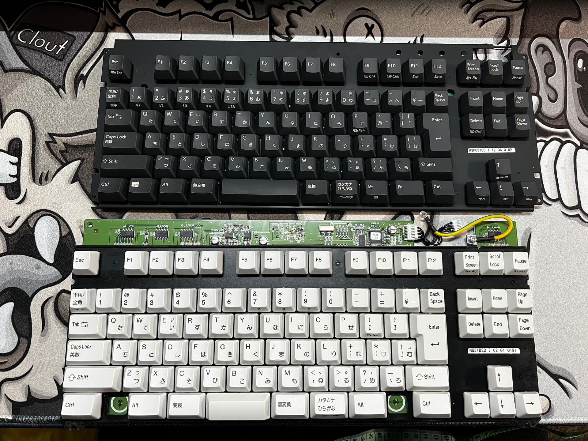
Top view of the R3 (top) and R1 91u (bottom)
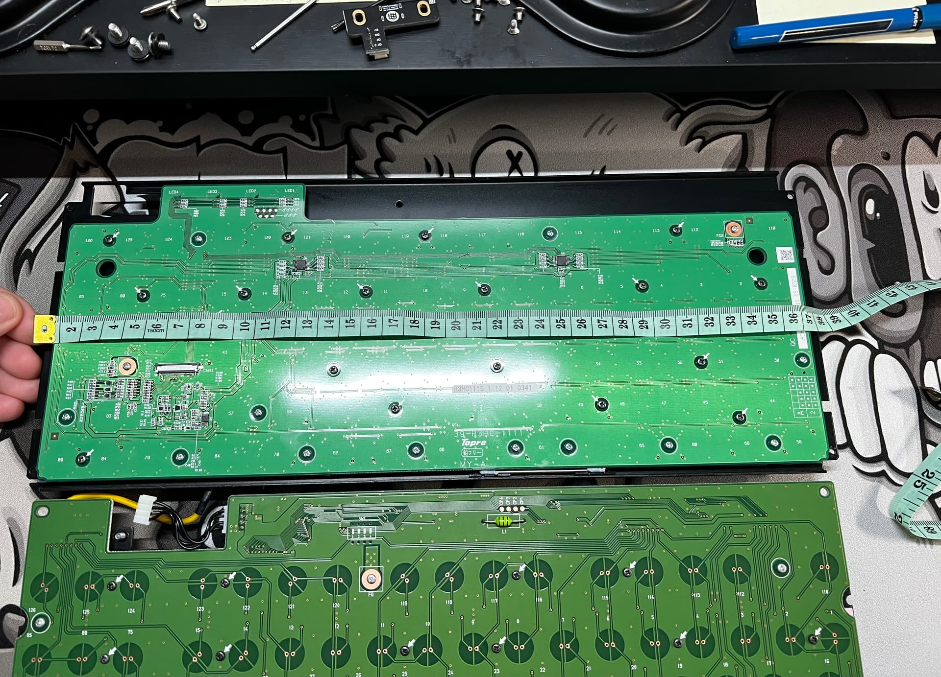
(This is a measurement of the plate from the backside of the PCB)
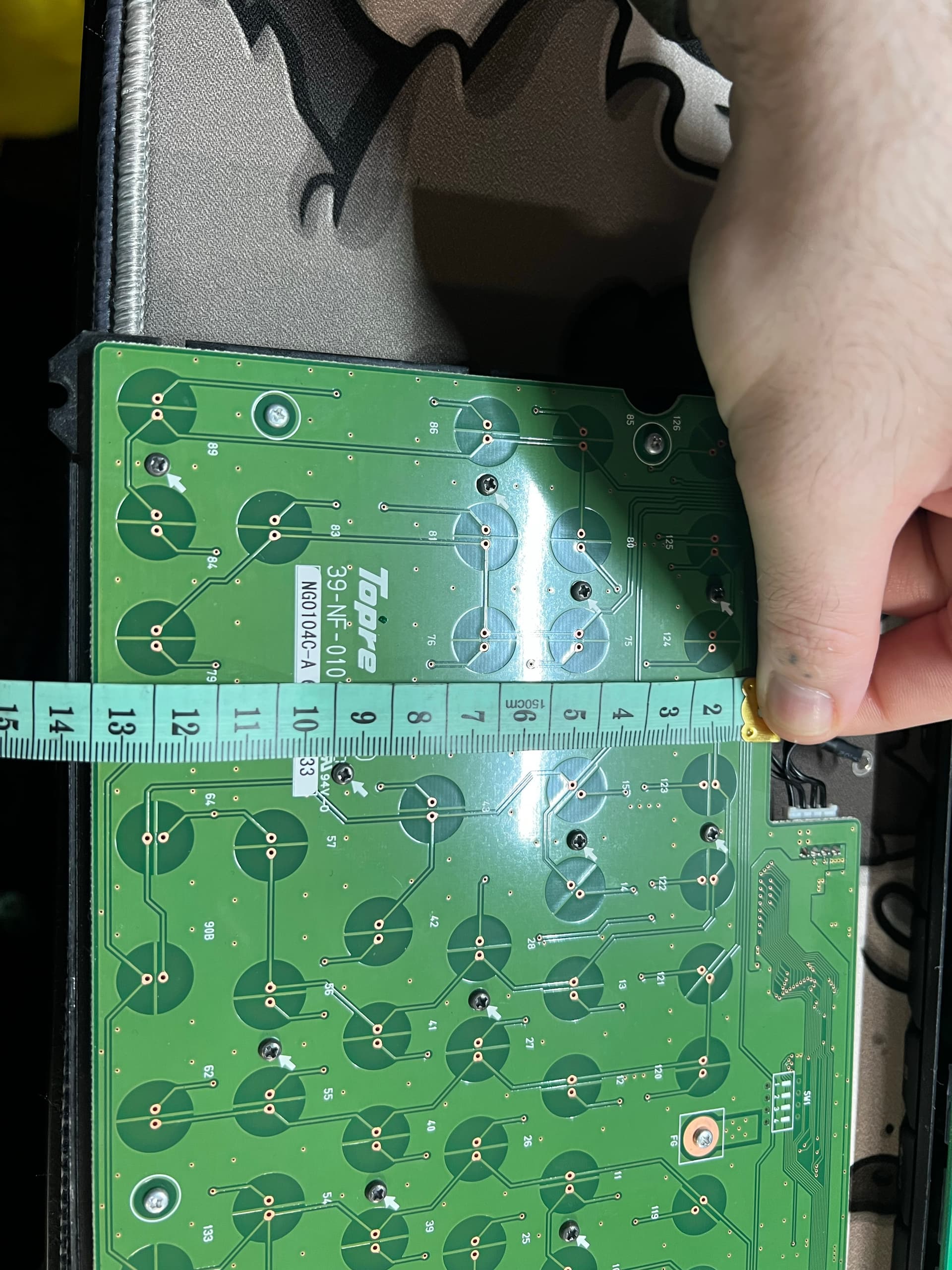
R3 plate length is 37 centimeters (top)
91u plate length is 36 centimeters (bottom)
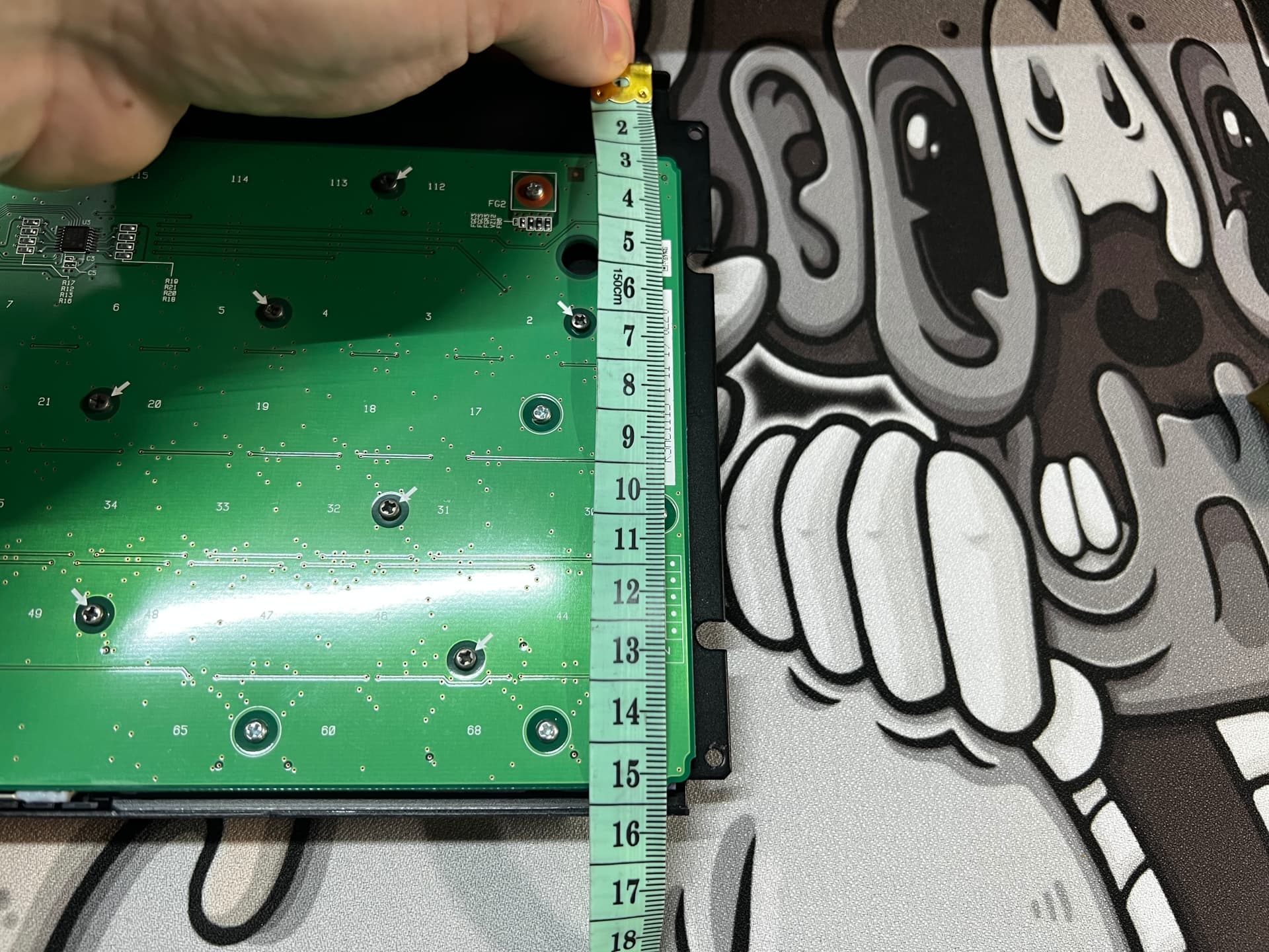
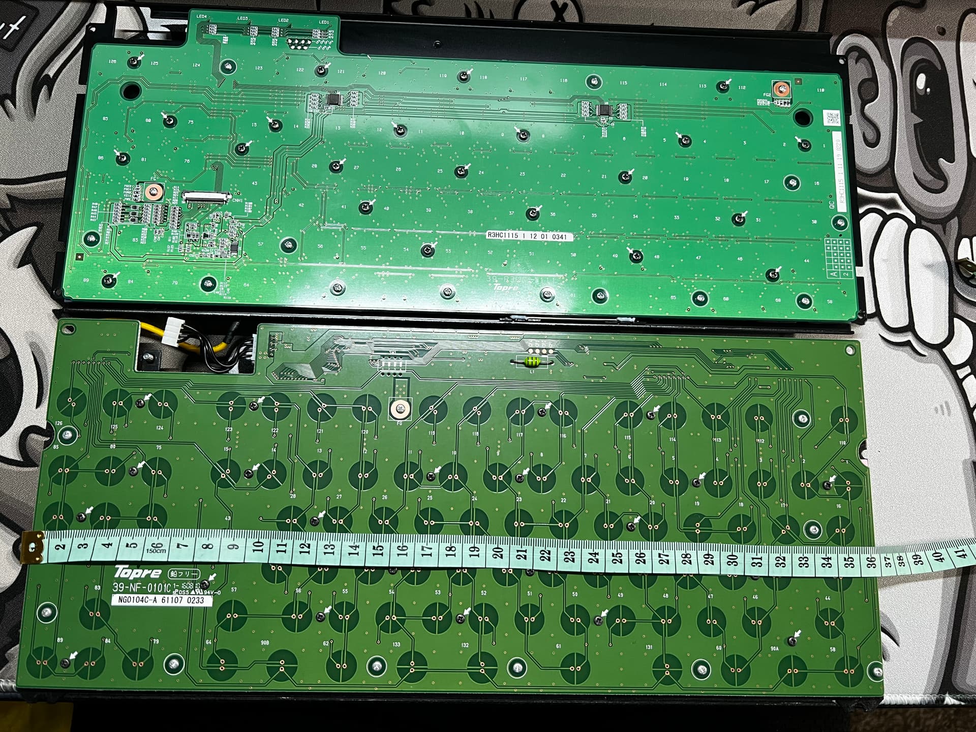
R3 plate from top to bottom is 15 centimeters (top)
91u plate from top to bottom is 13 centimeters (bottom)
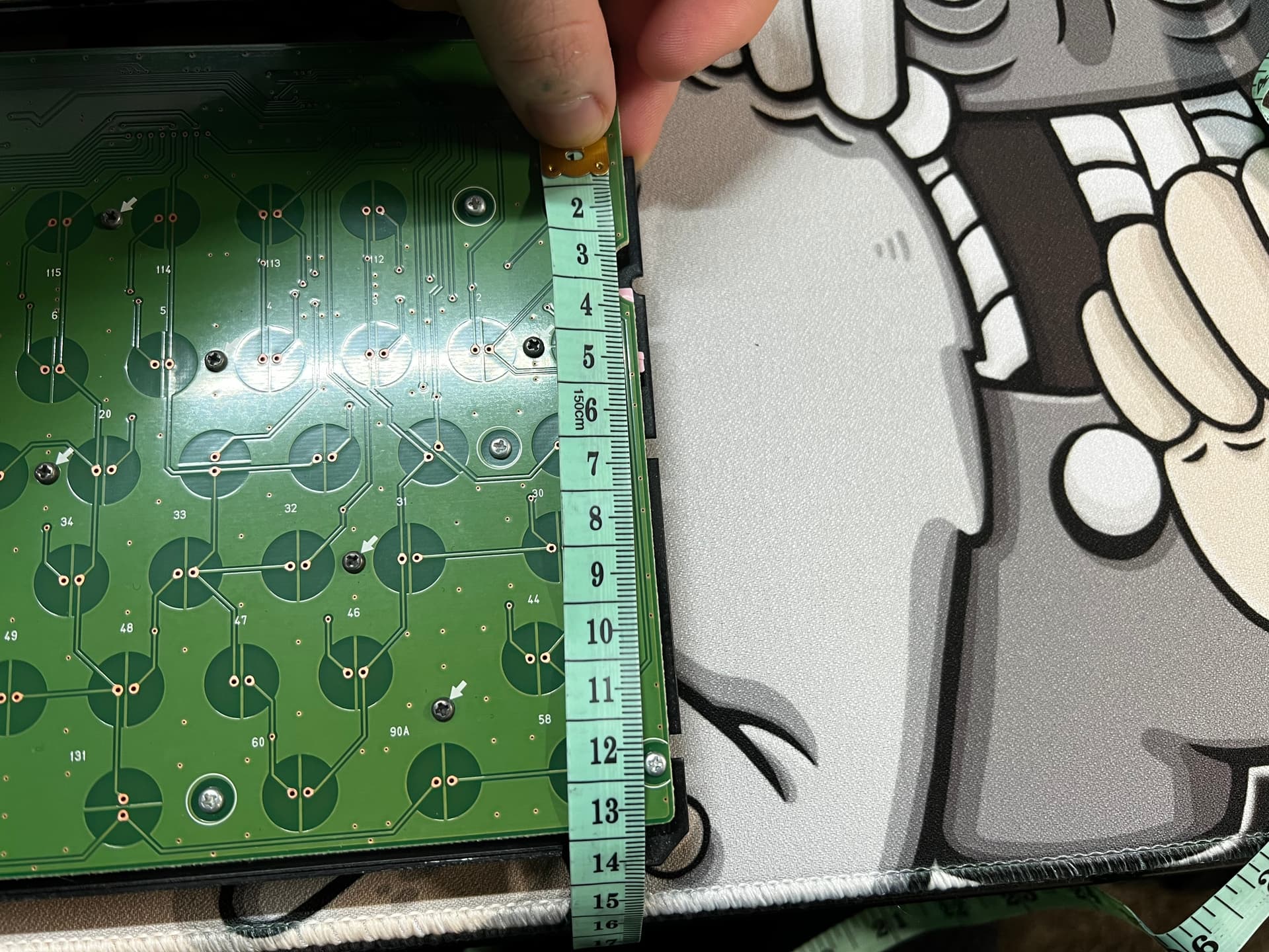
R3 shortest part of PCB is 12.2 centimeters (top)
91u shortest point on PCB is 13 centimeters (bottom)
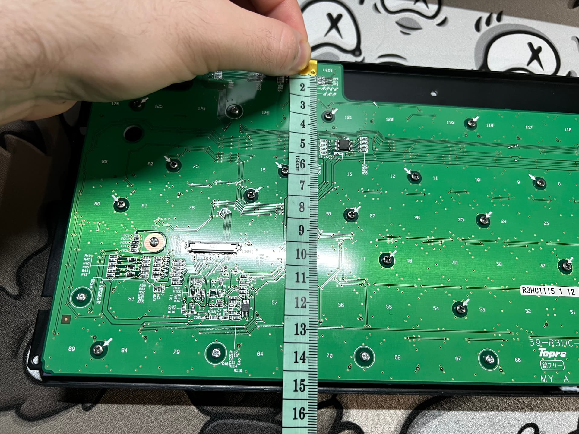
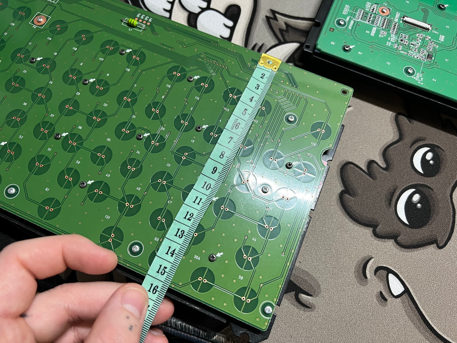
R3 tallest point on PCB is 14.3 centimeters (top)
91u tallest point on PCB is 15 centimeters (bottom)