I’ve been reading sporadic reports of Kailh hotswap socket getting pushed off PCB. This discussion is to share ideas on simple ways to secure the sockets.
Some untried ideas to start with:
more solder - (undoable) around contacts while keeping socket pressed against PCB?
crazy glue - (permanent) around contact pads and/or on sides of socket’s flat plastic parts?
epoxy putty - (permanent) cover the contact pad areas?
While all three of these are good ideals to better support the sockets, I think the biggest issue is people are putting switches in while the bottom of case is still on leaving the bottom of the PCB completely unsupported. I’m not big on hotswap as I much prefer my switches soldered in. In fact I don’t even own a hotswap board, but from seeing how the sockets are installed on to the PCBs I’d personally always make sure I got the back of the PCB exposed & sitting on a hard surface to support the sockets from downward pressure before installing switches in them. Especially since I have also noticed people having sockets pop out a good bit with all the hotswap boards using Kahil sockets. From the M-60 on the high end to cheap Chinese hotswap boards on the low end, they all seem to be effected by this.
Which is not a surprise considering they are surface mount components not really made to have any type of stresses applied to them. So while your suggestion would help a good bit to keep them from popping off the PCB when changing switches without supporting the back of the PCB. I honestly think opening the case & having the back of the PCB sitting flat on a table so all the sockets are supported from downward pressure would be the best solution to keep them from popping off the PCBs.
There seems to be a pretty obvious solution to me here - thick foam layer that allows enough give but still provides some pushback and support for the sockets. Granted, I am no engineer, but I have added foam to fix a particularly problematic socket in my own KBD6x R2.
This is a really good ideal to avoid opening your case every time you want to change switches! What type of foam did you use, I’d imagine it would have to fairly ridged to help support the sockets.
Just some of the relatively coarse black packing foam that’s all-so-common - I specifically cut down a layered-and-cut block of foam that originally held headphones. The same type of foam was also found in the packaging for the NIU Mini iirc, along with the Novatouch box I had.
Hi, I think I’m confused.
how does one push the socket off the PCB, won’t the pads on the PCB come off as well?
I also assume that the switches are PCB-mounted? wouldn’t it be easier to use plate-mount switches for hotswap board?
The sockets, when falling off, have a nasty habit of taking the pads with them if they were soldered properly. Thing is, a lot of the cheaper boards (igk6x, KBD6x) have cheap solder and the solder can fall off and leave the pad. Some boards have PCB mount holes, which is a good thing, as it allows for all MX compatibles to be used without trimming. Most, however, just have plate mount support, which is a shame. Hotswap builds, whether using PCB or plate mount switches, should always have plates, because typing on a plateless hotswap is a recipe for a dead board.
There seems to be a pretty obvious solution to me here - thick foam layer that allows enough give but still provides some pushback and support for the sockets.
This is a good idea but finding the right type of foam may take awhile to find because I don’t think any of us want to reproduce the problem just to see if it’s the right foam.
how does one push the socket off the PCB, won’t the pads on the PCB come off as well?
This hasn’t happened to me yet but I think it happens either when pins are misaligned or socket pad is not fully soldered.
I also think amount of force needed to insert a switch into plate is a factor. Panda remake/clone housings, for example, need a lot of force. Because inserting them also increase chance of breaking them on removal, I now file away side notches by about half before inserting them.
Socket pad desoldering problem may be due to brittle solder type when reflowing, typically one of the low temp kind with bismuth in it.
Just guessing that they are using these low temp solders because when tried to solder hotswap sockets with my heat gun at 300°C I saw that the plastic part melted a litle bit.
This seem not the same kind of plastic or resin as used in other IC/chips (maybe ABS or Nylon ?).
Better use your good old iron and standard leaded/lead free soter to do that.
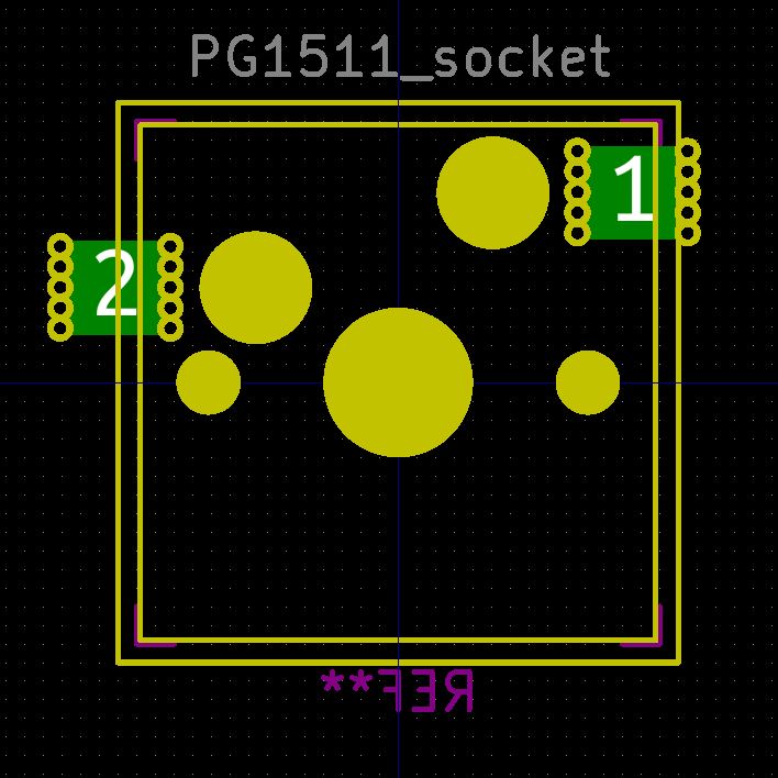
Also pad lifting from the FR4 substrate (the worst of all) may possibly be avoided with a custom PCB footprint design with thru holes added where mecanical forces are applied.
Didn’t tried yet on my own PCB designs, tell me what you think of the proposal (picture below).
I have had three sockets come off so far on preassembled boards, all down to dry solder joints, the pads were not removed from the FR4 though so I just soldered them back on with no adverse affects. Never had the same problem on my hand assembled board though as I used a lot more solder on the sides than you would get if they were reflowed.
Glad to hear that you didn’t had any pad lifting problem
I designed and soldered my own PCB with these sockets and was a bit anxious that it could happen.
For the moment, fingers crossed, it didn’t happened once.
Just like you I soldered all sockets by hand with sufficient amount of solder.
It is effective though i think and it’s been done. My wooden gk64 case has the hot swap sockets touching the bottom of the case. You can see the imprints of the hot swap housings in the fabric that sits on the bottom of the case when you take the keyboard apart.
Finally experienced an episode with Kailh socket. It started with the D key on the HTE60 board (Tsangan version of HS60 from 1upkeyboards) suddenly not working. It’s socket appeared OK but when I disassembled the board, I found that the socket could be wigged a bit.
Key started working again after resoldering the socket. While at it, I added more solder to rest of the sockets. I’m going to do the same to other hotswap boards I have next weekend.
I’m starting to think that these boards should come with the sockets unsoldered and do that ourselves, it is not much difficult than soldering the switches anyway …
Is there any way to repair when the pad has lifted? I tried to replace a faulty socket on my Planck PCB, but somehow managed to lift the pad from the PCB.
I never did that myself so I may give you wrongs advices here.
My take is to glue the pad on the PCB with 2 part epoxy glue.
If there is still the PCB track attached to the pad, take extra care not to break it during the process.
If the pad broked, then you’ll have to figure out how the key matrix is laid out (a multimeter is nice to have for that task) and solder a wire to make a bridge.