Securing Kailh hotswap socket

I never did that myself so I may give you wrongs advices here.

My take is to glue the pad on the PCB with 2 part epoxy glue.
If there is still the PCB track attached to the pad, take extra care not to break it during the process.
If the pad broked, then you’ll have to figure out how the key matrix is laid out (a multimeter is nice to have for that task) and solder a wire to make a bridge.

2 Likes

HI Rico, thanks for the tips. How can I tell if the PCB track is still attached to the pad?

It is very simple.
If you see the lifted PCB pad not attached to any copper trace then you’ll have to make the wire bridge.
If a copper trace is still attached to it then take extra care to glue the pad to the PCB and it is the only thing you’ll have to do.

1 Like

Hi Rico, I’m afraid I don’t even know what the copper trace looks like. Here is a pic of the PCB with the lifted pad. Are you able to tell if the trace has been detached?

Nice to see someone else having the same issues with these sockets. I’ve had problems with them on a Rev 6 Planck and I said I’d never use them again.

1 Like

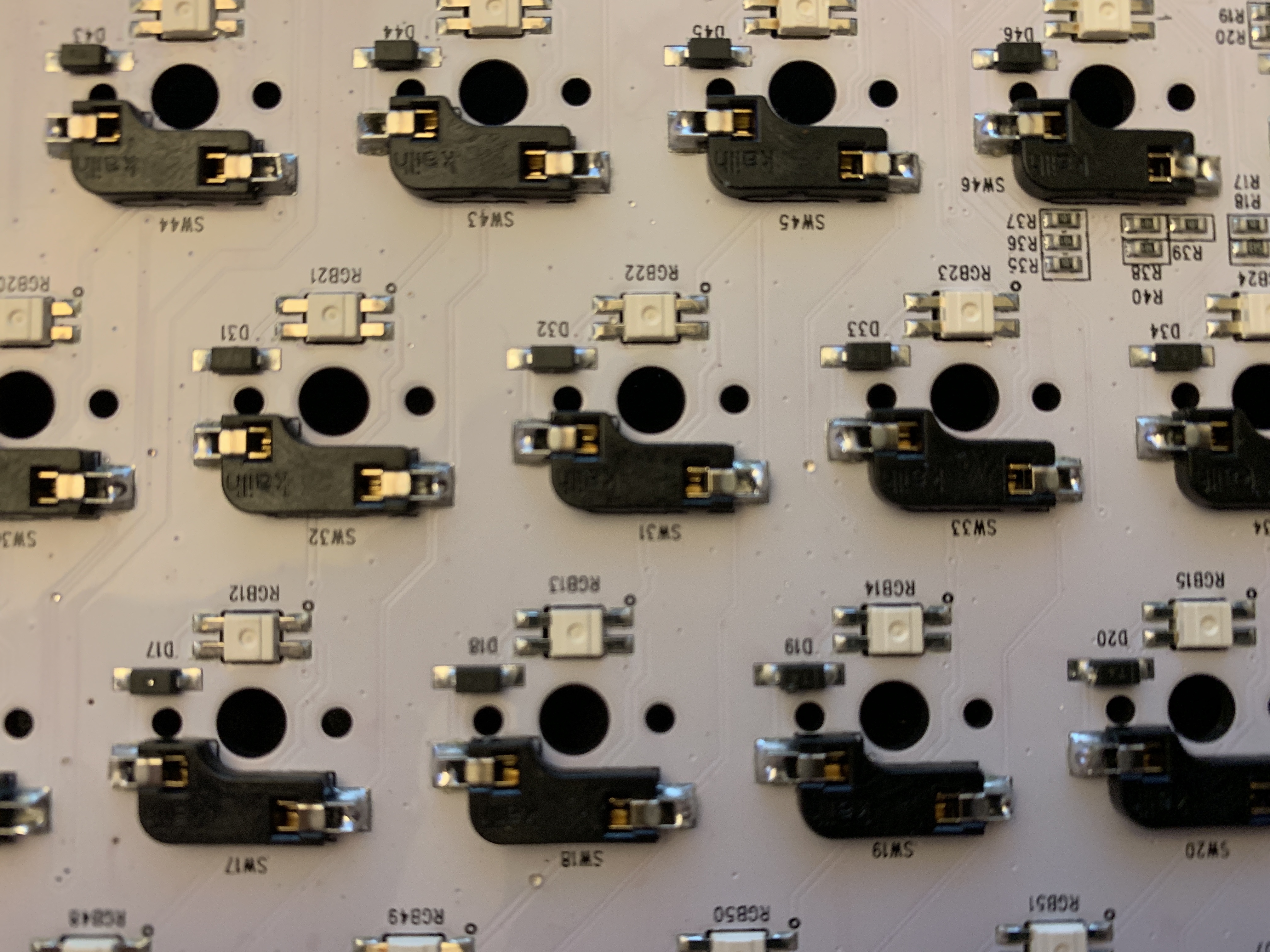
Amount of solder on Kailh sockets varies between boards. On KBD6X board I have, the area above the part touching the pads are practically filled with solder. In comparison, Planck rev6 PCB appears to have solder only on the padding, not unlike KBD6X RGB and 1upkeyboards’ HTE60 PCBs I have which I had to add extra solder to secure the sockets.

UPDATE: Here is one of the PCBs I resolder to secure the socket.

1 Like

I’m beginning to understand why some don’t like the sockets. After thinking they were far superior to soldering, I’m now realizing that once a socket comes off irreparably, you are screwed because you can’t even solder the switch the old fashioned way! Hot swap PCBs should have solder contacts in the pin holes for cases like these…

1 Like

With my current PCB in GB, people are asking out hotswapping. The argument I use is this, as I experienced it first hand:

Kailh Box and Outemu switches are what I’ve been using for some time. They both have very narrow leads and will fit nicely into the sockets…until you try Kailh Pro switches, which have leads almost twice the diameter. Then, the sockets become stretched, and going back to regular sized switch leads will almost always not work.

If you want the piece of mind that if you want to swap switches easily, but don’t really plan to, then use these sockets. But if you’re like me and actually swap out every couple weeks, you need something like Holtites.

1 Like

Makes sense. But for some reason, Holtites don’t get any love in the community. I wish there were a way to get more info about them, and a source other than industrial websites.

Hot swap PCBs should have solder contacts in the pin holes for cases like these…

Kailh socket pin holes maybe too big for existing PCB manufacturing setup. Maybe alternate contacts that won’t get ripped out along with bigger contact pads.

Not sure I understand what you mean, but I probably expressed myself wrong. After a Kailh socket came off my Planck PCB and took the pad with it, I thought I could just solder that switch instead; but the holes where the pins go don’t have metal contacts to solder to, and I suppose this mean the PCB doesn’t even support soldered pins.

There are some other Holtite style hot swaps which are said to be a great replacement, if not better.

Mill-Max Sockets are supposedly better.

They aren’t super duper cheap, but they will save you from buying multiples of the same PCB just so you can have different switches. Or they allow you to skip the headache of de-soldering a PCB.

1 Like

Thanks for the link—do you know if there is a tutorial anywhere about how to install these? Do they require soldering?
P.S. Are you 100% sure the link you provided is for the right size for computer PCBs? Just want to make sure, because I have no idea…

I got the link from here.

I can’t guarantee anything but that person seemed sure. Also I THINK they’re held in place by friction, but I could be wrong.

Gotcha, thanks!

The copper pad on the right is still there so just soldering the kailh socket on this part will be ok.

The big problem is that there is no copper pad on the left :frowning:
A copper trace has been cut somewere around were the pad was but can’t see it in the picture.
This one will be more difficult to solve: to make a wire bridge you have to kwow were to connect what and need a multimeter for that, also need to discover how the switch matrix is laid out.

1 Like

Thanks for confirming my suspicion that I royally screwed up. Making a wire bridge is definitely beyond my capabilities and the time and effort it would take would, I think, not be worth the trouble.

So sorry to give you bad news :frowning:
It may be more cost effective to buy a new PCB if you don’t feel doing that yourself.

Indeed, although since it’s a Planck, it would mean waiting months and months… Oh well!

Do you know someone who could do that for you?

I could try to do something(with no success guaranty) but I’m living in France, shipping costs may be already prohibitive to you.