At first I wanted to talk about the main PCB but in fact I don’t have much information to give and will not post pictures of it because it is not worth it.
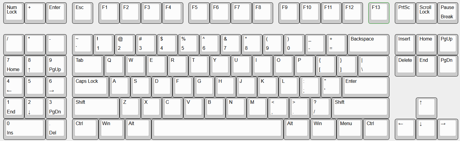
This has been a lazy design were I took the Aquanaut EC PCB as a base (because it proved to work very well) and removed one column (the one with the numpad plus and enter keys) and that’s pretty much it.
Still I made a change to adapt a custom made daughterboard PCB, this one will be much more interesting to talk about later in this post 
So let’s talk about the case!
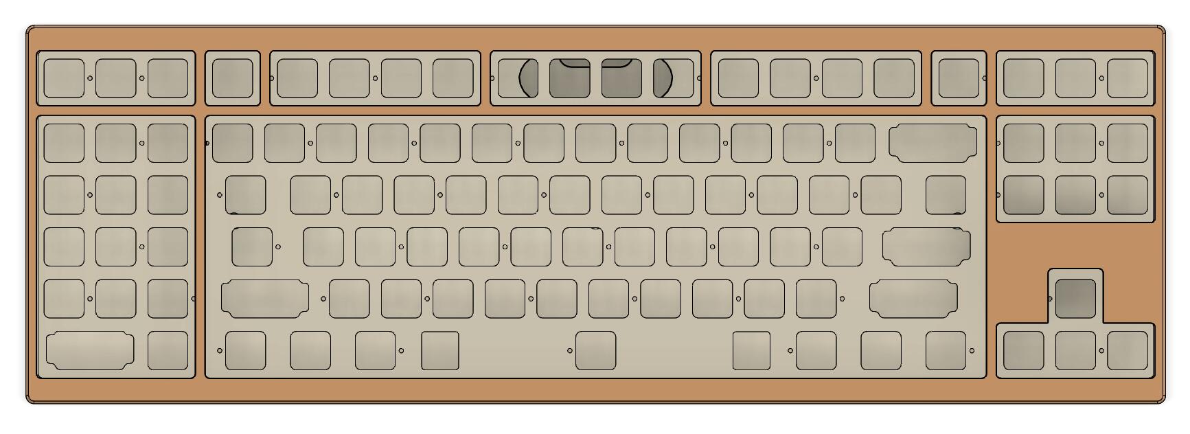
I am a sucker for big bezels but still like the harmonious Korean proportions.
So this time, at least from the top view, you’ll see a keyboard that is very Korean alike; this means 1/2U top/bottom and 1/4U left/right bezel sizes.
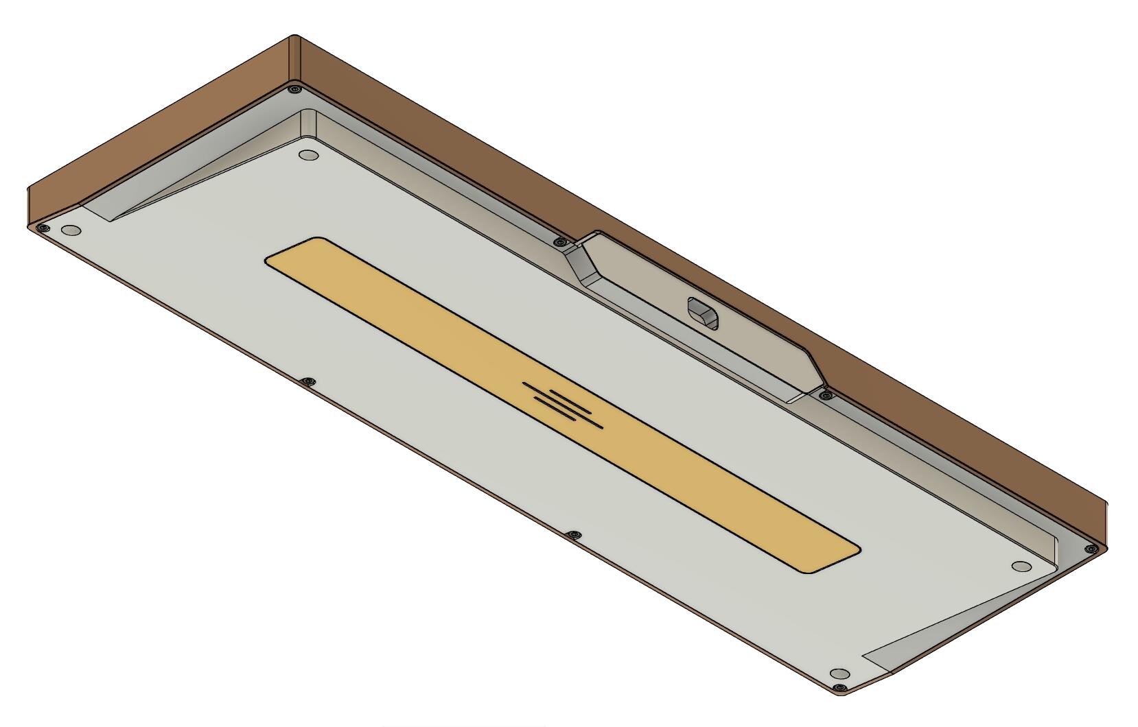
Even from a top isometric view it looks strangely like a GeonWorks F1-8X V2.
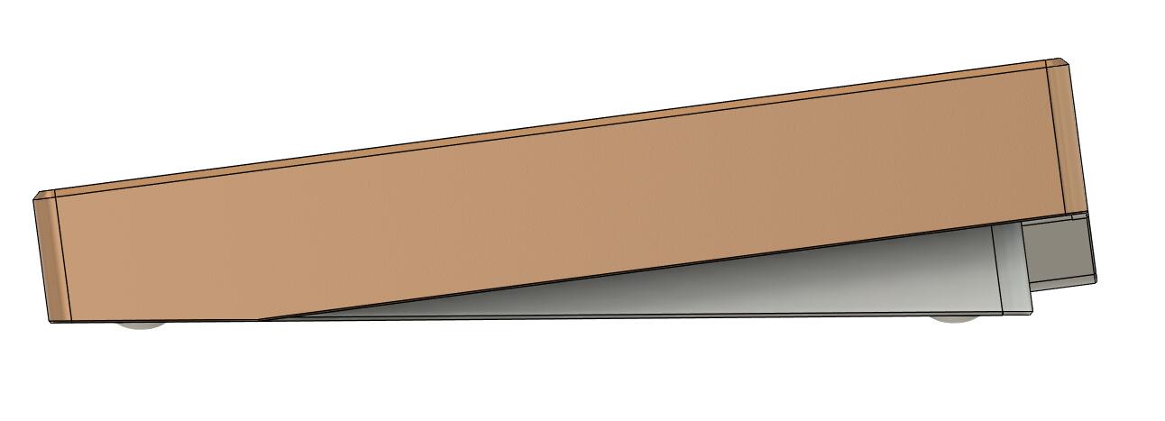
From the side this is a box and wedge design but you can see a strange protuberance on the back of the board.
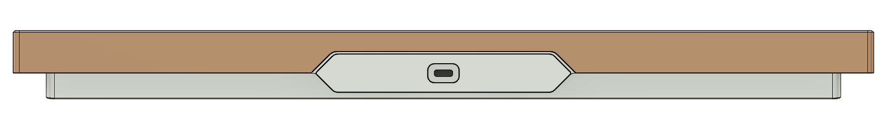
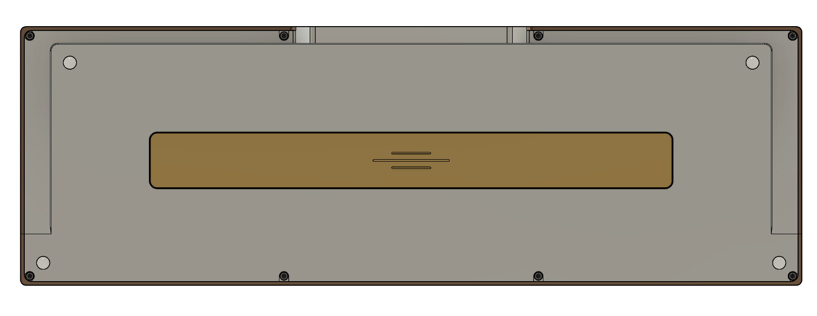
Here is the back view for a better view.
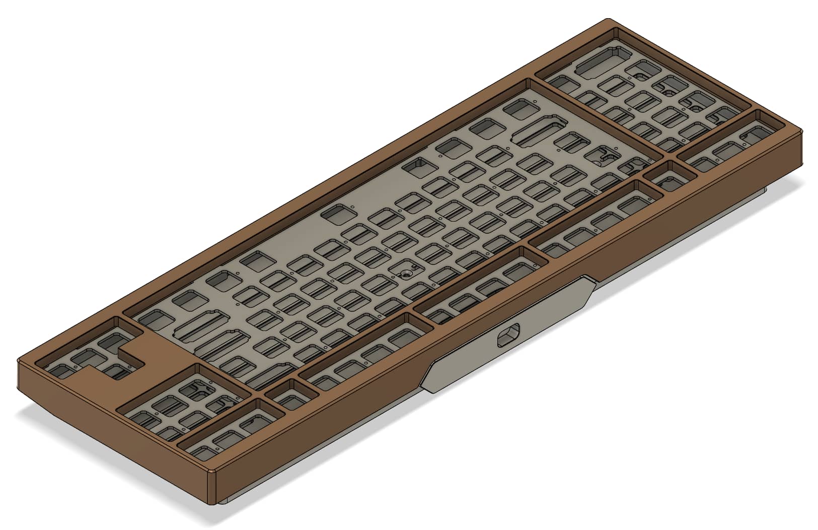
And back isometric views for better shape understanding.
The back shows the weight, the feets, and how the board is assembled.
No complex hidden screw design (still you see nothing when the board in on the desk), simple 7mm adhesive round silicon feets.
The brass weight has a simple symmetry symbol engraved on it.
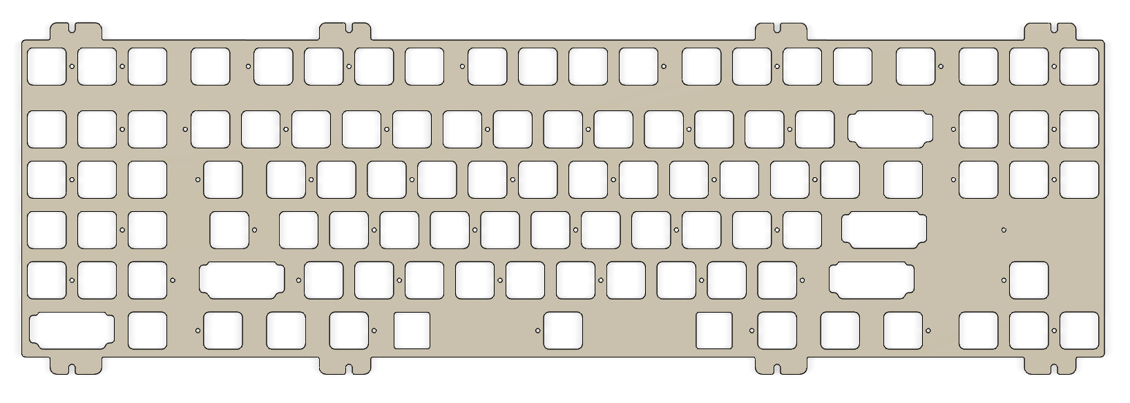
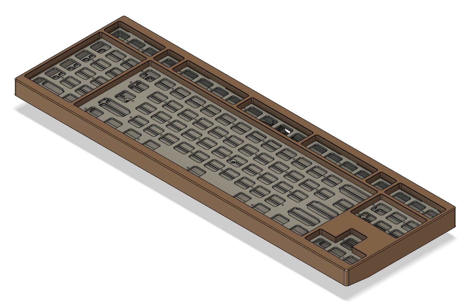
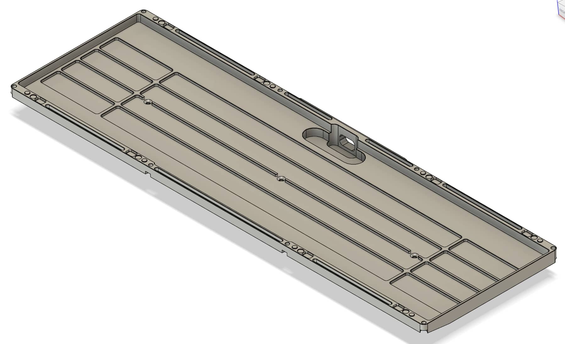
Here is a general view of the bottom piece:
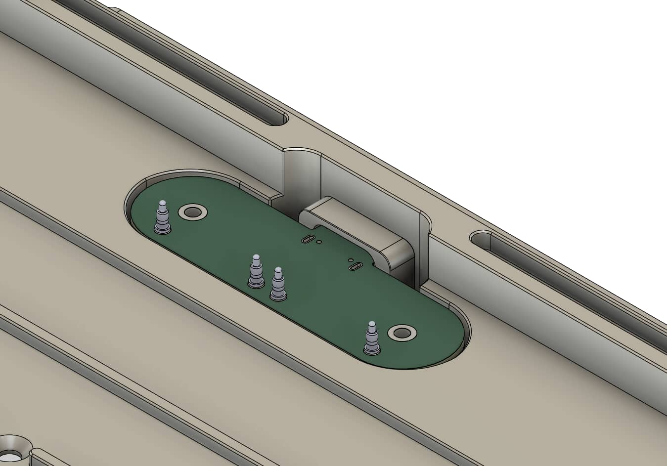
There is a hole on the back where the daughterboard will sit but no screw holes to fix it, strange isn’t it? We’ll come to this detail later.
Most of the alpha and nav clusters have cavities underside them that are 2mm deep.
Under those cavities the distance to the PCB is 4.5mm (2.5mm outside the cavities), this is to give ample space for air to travel and have bassier sound (the ‘thock’ factor that EC people love :p).
This is a mimick of what you can see in those plastic Realforce keyboards that have a lot of room between the PCB and the bottom of the case.
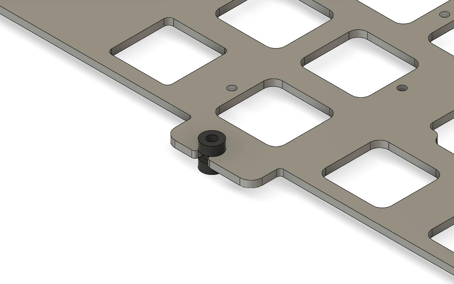
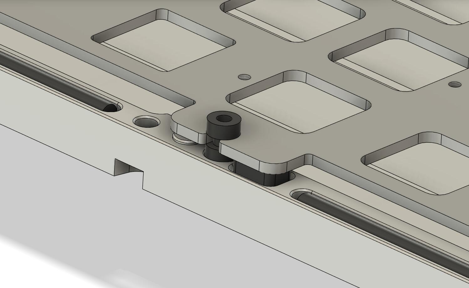
The front and back parts are quite busy, here is a closeup view below.
There are rails to place 3mm Viton (or silicon) Orings that will be in direct contact with the top piece; this is the same general principle as in the F1-8X (or the Aquanaut) but this time the plate is not sandwiched between the Orings.
The goal is to prevent the top piece to ring like a triangle instrument when typing, this is technically a force break technique even if the goal here is not to prevent the top piece to make contact with the bottom piece: the viton Orings are here to absorb all the top piece (and a little bit of the bottom piece) vibrations.
You can see the pole to limit plate travel to 1mm on the left of the mounting pad and the 3mm Poron pad(optional) on the right of the pad.
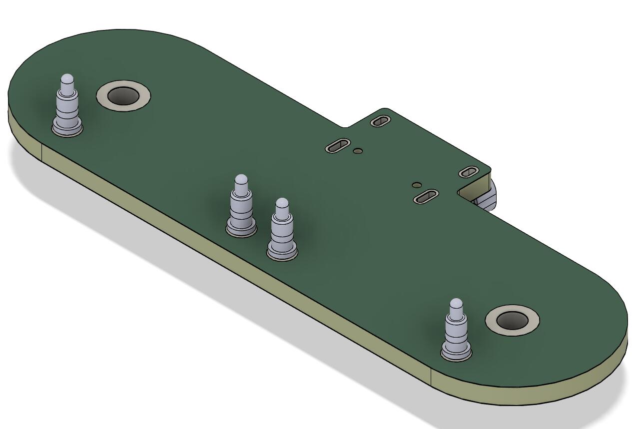
The daughterboard PCB is quite special.
It is not fixed to the bottom piece but to the main PCB itself with the help of PCB standoffs and screws and make electrical contact with the help of pogo pins.
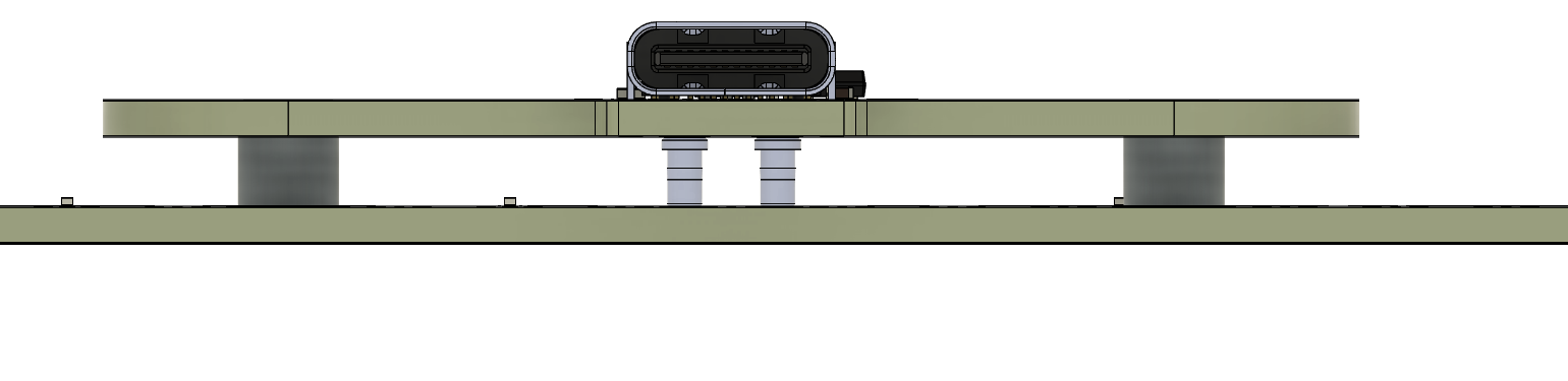
This allows the USB connector to sit low in the case and facilitates disassembly/reassembly: I came to hate JST cables with a passion 
The problem with USB connectors on the main board is the dilemna associated with it as you need empty space around the connector to allow the PCB to flex or tilt without the connector to make contact to the case (and potentially break).
Too little of a space and your USB connector can easily touch the case (but it is darn pretty) or big space and it looks ugly.
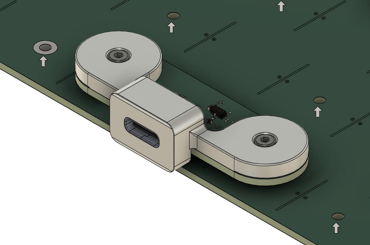
The solution has been to create a USB cover that is fixed to the daughterboard, the best of both worlds (well I hope).
This piece will be 3D printed in aluminium.
Here is a look at the daugtherboard with the cover placed in the bottom piece, this is difficult to see but there is a gap between the back of the USB cover and the pottom piece so that everything can move without any contact.
The board is not a chonker given it’s size, weighting only a little over 2KG with case, weight and plate, but I hope the sound will still be good.
Other dimensions are:
- 7 degree typing angle.
- Front height is 17.5mm.
- Adjusted front height is 18.5mm.
- Adjusted front height with feets is 19.5mm.
The whole board design is mostly complete and in carefull review phase before going to manufacture.
I hope to send the design to manufacture by September.
See you later!