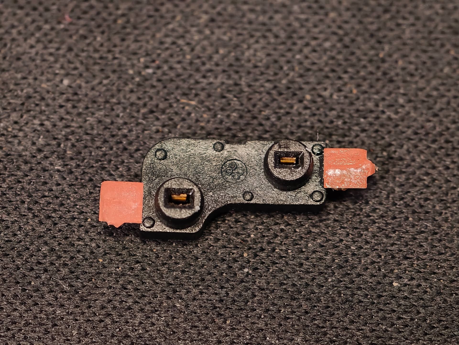
When I was putting new switches into my Akk Monsgeek M3W keyboard, the hotswap socket for the spacebar came off and unfortunately also with the pads. I feel really bad because it destroyed my excitement from the new build and also this particular keyboard has a special place in my heart. Not to mention getting a new PCBA is almost impossible.
I have read people with similar issues and apparently there should be an option of a wire bridge/jumper fix?
So if I understand it correctly, I should:
superglue the socket back in place
using a 28awg wire connect one side of the socket to a nearest diode?
using a 28awg wire connect the other side of the socket to some other corresponding socket?
Since I am not really experienced in PCBA design, could you please navigate me to which diode (and which part of it) and to which “heathly” socket and which part of it should the wires go? I have a friend who can do the soldering but unfortunately I don’t have a multimeter.
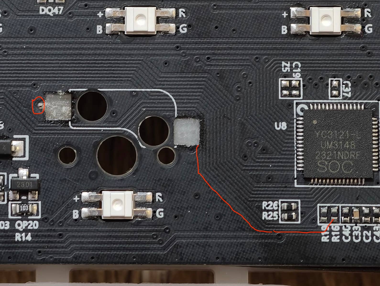
I tried to take very high resolution photos of the board so maybe you will be able to tell? Thank you so much in advance.
If you are planning to do some soldering, make sure you also have a multi-meter. A cheap one will generally be sufficient for stuff like this. You can carefully scrape away the solder mask right next to where the pad tore away, like literally a millimeter or less, then set the meter to continuity mode and check which diode and which column your hot-swap socket was running to.
Also, be careful. My inability to repair a torn pad on a spacebar’s hotswap socket three(?) years ago has led to terrible things, like designing my own PCB’s and cases.
Thanks for the reply. Should the PCB be plugged in while testing with the multimeter or not?
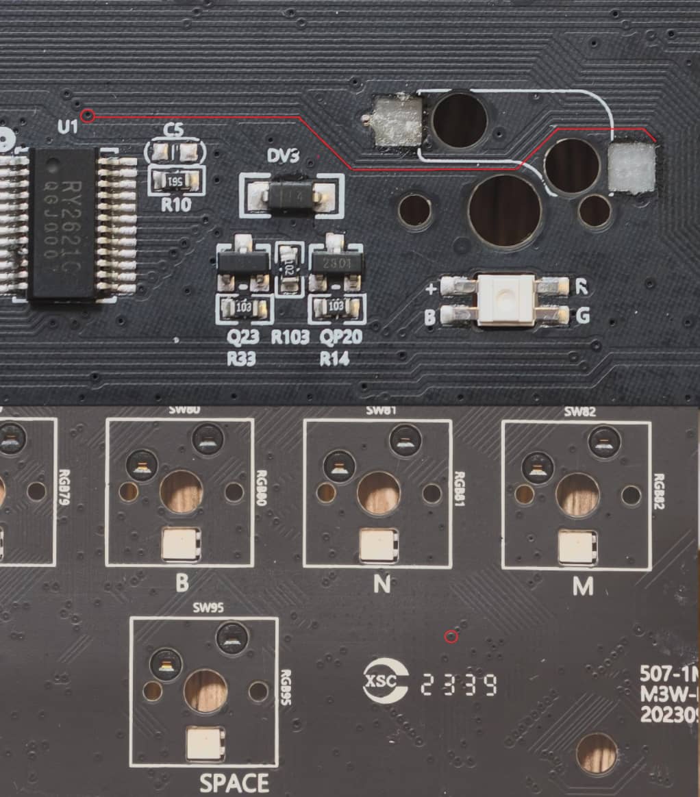
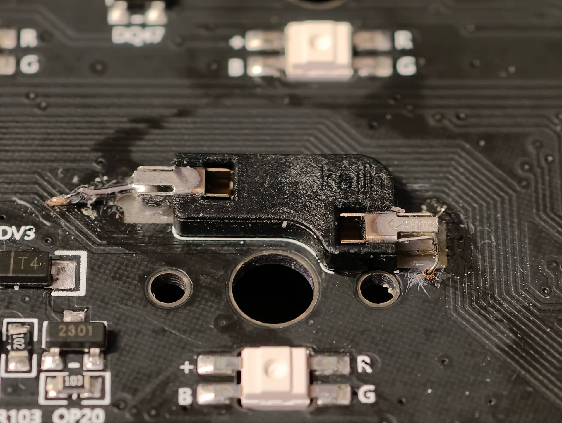
Also I noticed it look like there is a bit of a trace left on the left side of the socket (ground?). And it looks like there is a trace going from the right side all the way to a component (diode?) R16. Do you think its plausible or am I just imagining things?
You wouldn’t need the pcb to be plugged in to do continuity testing with a multi-meter. The meter will supply enough power to check if the traces are connected. It can also be maddening to visually track the traces, but if you can find just a bit of the trace right by the pad, you can check with the meter. The one you’ve highlighted could be it, but I admit it’s a little hard to tell, and it appears you’ve traced it to a resistor (R16) versus a diode. You can also visually track and electrically trace the one that I think is jumping off from the top of the pad and see if lands on a diode or another key. This is really pretty tedious business, and you may ultimately find it helpful to try @Deadeye ‘s idea of looking while the PCB is plugged in with a simple jumper of some sort. You could even try shorting nearby combinations of rows and columns to see if one generates a space keypress, then solder those to your physically repaired socket. It would be nice if this board had open source firmware, as we could then check the code and tell you which “coordinates” would get you a space press, but trial and error could work out. If you want to upload a high-res photo of the entire PCB (front and back if they’re both accessible), we might be able to give you a better set of advice.
Ahh, I see. Sorry about that. In looking, I’m not quite sure. The board doesn’t seem to be using a single diode for every key, so it might be doing something with shift registers or other electronics or firmware. I see that trace terminate at a via, but sure enough, I can’t trace it on the front-side. You may be stuck either waiting for someone smarter than I am or trying to “blind squirrel method of looking for likely candidates to check. You can also see if Monsgeek might send you a diagram of the matrix, but this one’s got me flummoxed.
Hello again.
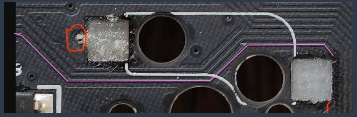
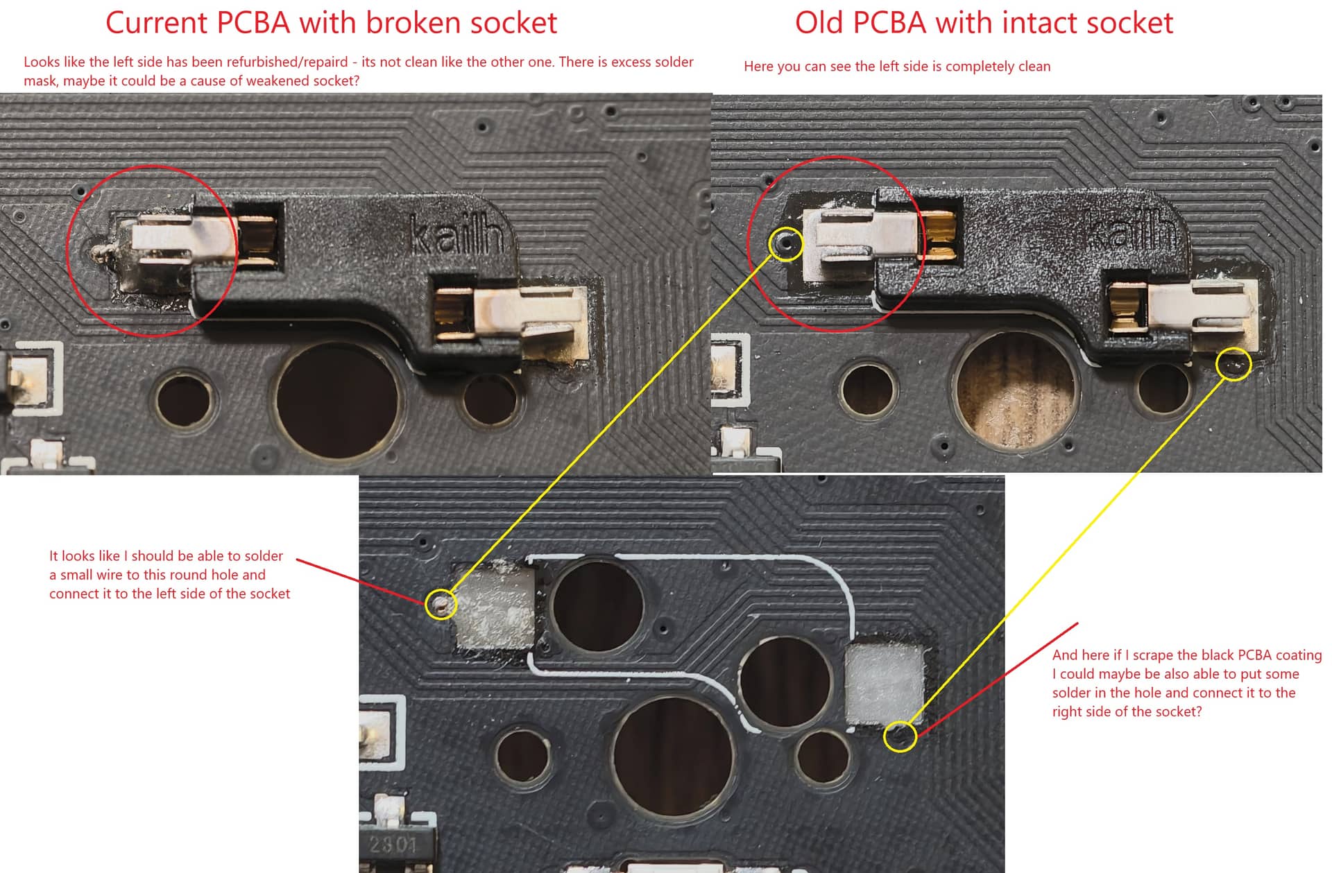
I was once more investigating the photos and comparing my current PCB with the broken spacebar socket to my old burned PCB with the socket intact and it looks like something fishy went on with the left side of the socket in my current PCB.
Anyway I think I might have discovered the connection points and hopefully it will be possible to connect to them. What do you think?
It’s certainly possible. Try to get them both exposed and test with the board plugged in by bridging with some wire or tweezers. If gives you the keypress, you should be able to make it work. The sockets weren’t really meant for this, so just be careful you don’t overfill and make the socket physically unusable, though I suppose there’s always putting the switch in first and just rolling with it if you accidentally end up with a non-hotswap spacebar. Be very careful with that socket, especially inserting switches, for the rest of the board’s lifetime.
If I was going about this repair and those VIAs are indeed the connection you need to make, I would super glue the socket to the board. I don’t know if you have the original socket with the pads still attached from the board. But if you do, I would super glue those squares back down to secure it. If you don’t have them, you might be able to get some super glue around the holes where the socket goes to hold it there. But I would glue and secure first, solder to VIAs second.
And like @wjrii said, you’ll need to take extra care when swapping down the road. You’ll want to make sure you take the board apart and support the socket on the back when pushing the switch in.
perfect! Yes, some super glue on those pads and press them on the board to cure. But you need to test to VIAs to make sure you have the right connections. You can connect them to the pads or run a wire (or solder bridge) to the hotswap metal arms. Either one will be fine. I’ve done both. I prefer to run a wire from the trace to the metal hotswap arm.