The Leyden Jar, a tentative PCB replacement for the Brand New Model F Keyboards

I am happy to say that things progressed quite a bit!

The first step was to design a good matrix scanning program.
This is more difficult than it looks, as during my simulations I saw that I had only 1us window to read all the row values.
So it works no problem using CPU polling if you want to read only one row (and this is what I did to check that the PCB was working as intended).
But reading 8 rows by reading IO pins using the CPU and expecting to have consistent results is another matter…
Several factors can make this process using the CPU unreliable:

  • We could simply not have time to scan all 8 row IO pins, and we’d miss key presses.
  • This could ‘work’ most of the time, but be interrupted by an external code or kernel process and miss some keypresses as a result.
  • The timing at witch to read the IO pins is important, a bit sooner or a bit later and we can have slightly different results; we need to have this timing very consistant (I measured an optimum time of 0.8us between activating a column and reading row IO pins).

While current Model-F PCB is reading row IO pins using CPU “as fast as possible” (said Tom Wong-Cornall in it’s blog), this not gonna do it at least for my design.

But I knew that from the start thanks to the LTSpice simulations and selected the right MCU for this task :wink:
Hello RP2040 and it’s PIO feature!
I should be able to make a PIO program to do the matrix scanning without CPU usage and very tight and consistent timings.
I took me a while to do that (my first time doing PIO stuff and this is another specialized hardware to learn) but finally had my PIO matrix scanning program working like a charm :slight_smile:

Second step, test this matrix scanning program on the real beast, my own Model-F F77 board.
For that I needed to desolder the current PCB and solder the Leyden Jar PCB.
This was a big step for me as it would not only determine that my PCB work on the real hardware, but also would validate that everything fits nicely mechanically.
Not entering too much into details, I have to say that the official PCB has been a bitch to desolder :frowning:
But here is the result:

This is ugly but had to put back the kapton tape as the lower part of the PCB is touching the bottom case (as with the official PCB).

Happy that everything screws and fits as intended, there is even place for my SWD connector for developping/debugging!
Debugging session that started shortly after:

So how does it works?
First the detected voltages are lower than in my simulations:

  • This is normal as we now have to deal with parasitic capacitance and inductance.
  • I have very early timings in my PIO program, this could improve in the future (already tweaked a few things to make it better).
  • We are using 3.3V for the column IO pins instead of 5V for the official PCB, having a lower voltage peak was more or less planned.

But the most important thing to have is consistency and we have excellent consistency here:

  • We have only ~1mV deviation for the same keys tested during several tests sessions.
  • Variance between all unpressed keys is 8mV at most (looks to be the same with pressed keys).
  • We have a peak voltage variance of ~30mV between pressed and unpressed key, this is more than enough to perform a very stable key press detection :slight_smile:
  • Pressing several keys at once or only one does not look to change the detected peak voltage much.

I think that the key of this consistency is to have a reliable 3.3V voltage source as it is generated by the onboard voltage regulator.
On the other end, I had some undetected keys problems with the official PCB when plugged on my shitty USB hub; this may be explained by some fluctuations on the 5V line, that even the calibration program can’t handle. No problem when plugged on my PC USB ports though :slight_smile:

To conclude this will definitely work like a charm and I am excited to start writing a VIAL firmware to confirm this.

On top of that there is another good news, the scanning process is quite fast: as of now scanning all 16 columns and 8 rows takes only 640uS (40uS per column).
This could change in the future:

  • If changing the timings helps to have better peak voltage detection it could end to be slower.
  • But it could also be possible to have something even faster :stuck_out_tongue:
3 Likes

This is sounding like it’s going to be better than the PCB the Model F77 ships with.

1 Like

Those last days I worked mostly on having an early QMK/VIAL firmware working on my F77 board equiped with the Leyden Jar PCB.

Although I previously had a ‘bare metal’ program using the Pico SDK that demonstrated that the hardware was working nicely I was afraid to find many QMK integration problems.

Problem 1:

When talking about QMK firmware there is a significant software fragmentation issue.
This started by the VIAL fork in order to have an opensource alternative to VIA software.
Then due to the need to add support to the RP2040 MCU, things got even worse and you can find on the net many git repositories that gives early support for it.
Fortunately QMK has recently added official support of RP2040 into their main branch, but VIAL did not yet merged this support to their own repo.
So had to select one of the numerous git VIAL repositories for my integration task.
Fortunately Zykrah, very active in VIAL Discord, did all the tedious task of merging official QMK RP2040 support to it’s own VIAL repository:

All my work will use this repository as a base.

Problem 2:

As my matrix scanning is using PIO, I was not sure yet what kind of support would be available for that, if any.
Looking at the QMK source code, there are official support of WS2812 led drivers using PIO.
IO pin configuration is using ChibiOS HAL api directly and for PIO stuff the Pico SDK API is used.
Let’s see if I can do the same thing for my PIO matrix scanning program.

I had to perform different tasks in order to hope to have everything working:

  • Review QMK source code to understand how/what RP2040 support was added.
  • Configure a work enviromnent to be able to use a SWD debugger.
  • Review previous QMK firmware source codes that implement F77/F62 firmware using the official controller, mostly to understand or reuse how physical rows/columns are arranged.

And this last task proved to be more complicated that planned: to my surprise I could not easily reuse the work already done.
So time to start a debugging session and see what happen when you press the buttons, came with this ugly postit writeup of the matrix reverse engineering:

Fortunately using PIO proved not to be the headache I was fearing.

I was soon greated by the VIAL keymap display :slight_smile:

And finally could validate that all the keys were working with the matrix tester:)

It is very early, need a lot code polish and add missing features, but it works !

Things that work:

  • All keys work.
  • Storage settings on external EEPROM works.
  • Storage settings on RP2040 flash storage also works! I was surprised by seeing this feature added in QMK repo. Now need to choose between EEPROM and flash, if flash is selected I could remove the EEPROM chip for future PCB revisions.
  • Key commands to reset the MCU and erase the storage settings (EEPROM or flash) are also working.

Things not done:

  • Implement a proper voltage threshold calibration program, as of now it is harcoded and may not work on other boards.
  • Implement solenoid support, unfortunately I don’t have such hardware at the moment so this task alone could take time.
  • Tidy up code, fix bugs, add F62 support.

Happy man I am :slight_smile:

4 Likes

The Model-F soledoid and it’s driver juste arrived today, ty very much @Ellipse for having sent this so quickly!

So now on to try to make it work!

I already checked that the solenoid connector on the Leyden Jar PCB was correctly wired, good :wink:

I could work a bit on the software part also.
Having the connector pins connected to the I2C IO expander makes things a bit more complicated as QMK firmware does not handle this case at the moment.
With a bit of cheating and after studying QMK haptic/solenoid management code I could come with something not too terrible.
But I’ll definitely assign 2 MCU pins for a future revision of the PCB, this will make it more QMK friendly for the implementation.

The biggest unknown is now if I can drive the solenoid with 3.3V logic instead of 5V, time will tell …

2 Likes

Was the time to work on the solenoid support this WE.
And to discover if a 3.3V logic would be enough to drive it correctly.

I had read long time before the datasheets of both the current limit and the darlington array chips that are used inside the solenoid driver PCB.
At that time I concluded that a 3.3V signal would be enough to make everything working.
It is time to confirm that I guessed well !

Here is my current test setup in picture with everything attached:

After a long time of frustrations, numerous failures, and fear that in the end it may not work, I finally managed to make it work perfectly :slight_smile:
And oh boy this thing is noisy as f**k :smiley:

I have been very lucky up until now, having everything working as hoped.
Of course this design is still not perfect and may need further investigations and probably a revision 2.

Things that are still to do:

  • Cap sensing voltage variations are smaller than I intended, need to investigate how to improve that.
    This does not prevent to make Model F keyboards work very nicely, just that with more columns used things could get more complicated and would prevent BeamSpring keyboards to work reliably enough. I could try to improve this my modifying the current revision of the board.

  • Solenoid is driven by IO pins from the I2C IO expander chip. QMK has native support to only direct MCU IO pins usage; had to do little code tricks to make everything work. Would be best to use MCU IO pins next time.

  • Current design uses 2 I2C devices; again the QMK API does manage only one I2C device, I had to rely on ChibiOS API to drive the second one, complicating the code a bit. I’d wire all used I2C chips to only one I2C device for the next design.

  • External I2C EEPROM chip is now not needed as QMK has official support for EEPROM emulation using RP2040 flash storage; I tested that both were indeed working but would remove the external chip to reduce BOM (and then cost).

  • @Ellipse would like to have 2 additional columns to drive for possible future BeamSpring projet, like for example a 122 keys battleship. I saw a possibility of doing that and may add it in a future revision.

See ya !

2 Likes

Hello all!

Long time no see in this thread, did you thought it was a dead project ?
Far from it :wink:
It fact I continued slowly working on it, mostly on the firmware development side.

As I had little visibility on how this controller would work on other boards than mine, I needed someone with other variations of capacitive keyboards to help me.
And after discussing with @Ellipse he kindly accepted to give me some help on that task.

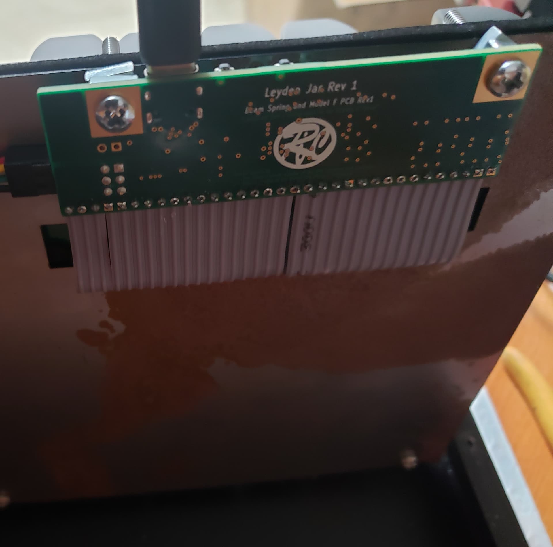
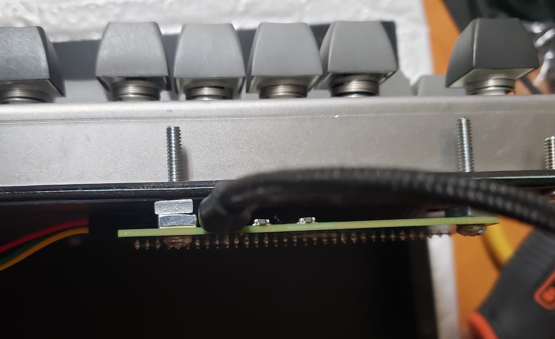
After receiving the Leyden Jar PCB he decided to solder it to one of it’s Brand New Beamspring Round 2 Full Size keyboards, our goal was then to try to make the Leyden Jar controller PCB work with this hardware.

Here are some shots of the Leyden Jar PCB assembly on the Beamspring Full Size, courtesy of @Ellipse.

As I didn’t have the board on hand, making the controller work on it was a complicated matter.

First I had to figure out how the switch matrix was organized and did a complete visual reverse engineeing of the beamspring PCB plate based on images provided by @Ellipse.

And also had to find the correct values for the calibration process.

After quite a few back and forth exchanges and firmware revisions we finally managed to do it :slight_smile:
There is now at @Ellipse workspace a Brand New Beamspring Full Size Round 2 keyboard with a Leyden Jar controller working nicely with solenoid and leds support, than you very much for your great support Joe!

Now is this controller perfect ?
Of course not, even if the most important feature, the capacitive sensing technology, is working very reliably.
So it is now time to make a revision 2 of this PCB and try to make it perfect.
The plan is also to add two additional columns, if possible, for future keyboards with a lot of keys like 122 keys battleships.

See ya people!

1 Like

This is interesting to me, as I’m becoming more interested recently in the new Model Fs after a surface-level look a while back. Thanks for the update.

1 Like

And with recent Joe announcment for selling IBM Model M like keyboards with Model F technology, this makes the appeal even stronger :wink:

1 Like

Whaaaa?

1 Like

Yes, look at model f website :slight_smile:

1 Like

I have big news people :slight_smile:

The Leyden Jar design and software is now officially open source under the GPLv3 licence!

The Github repository is available here.

Have a good dowload and reading session !

3 Likes

Amazing work.

As a prospective owner of one of the newer Model F keyboards and someone whose experimented with embedded development from time to time I have a few questions about this project.

  1. How’s the consistency of the matrix scanning and USB report frequency compared to the xwhatsit controller? As I understand with other keyboards, not all MCUs have consistent performance when running QMK with stricter timing requirements.
  2. The xwhatsit controller has a signal level monitoring utility to diagnose capacitive sensing. Does analogous functionality exist for the Leyden Jar, either as a utility or existing in concept but needing a utility written for it? :slight_smile:

Best regards

JTL

Hello @jtl !

The matrix scanning is entirely done using PIO hardware of the RP2040, it is very consistent in term of timing and gives very stable results during use.
The matrix scanning time is also very short (at 640us) and as the USB polling rate is set as 1ms you can expect around 2ms latency from the keyboard to the PC.

I already wrote one although it is very basic and not user friendly at all, it is just enough for me to look at useful data when troubleshooting.
It would need a lot of time to make a monitoring tool like for the xwhatsit (make by Pandrew), not a priority for now but maybe in the future ?

Best Regards,

Rico

Excellent. That’s one less problem to worry about.

I don’t know when I’ll have the time to potentially work on it, but I wouldn’t mind seeing what you have so far as a starting point.

Best regards

JTL

I may in the future add the Windows executable version of the tool in the Github repository.
In the Leyden Jar firmware source code there is some code to communicate with the tool, could be easily extended in the future if needs be (the communication protocol runs on top of the VIA/VIAL protocol, both are usable at the same time).

I just received the Rev3 Leyden Jar PCBs from JLCPCB, and also PS2 AT to USB daughterboards.


I’ll have to find time to solder this new controller to my F77 in order to check that everything works and tune the firmware code.

2 Likes

Hello everyone,

A little bit of news about the Leyden Jar Revision 3 PCB.
And before going to explain the validation status of this new PCB maybe explain a bit why another revision of the Leyden Jar PCB (after all the Revision 1 is already working nicely) and a bit of news on the Revision 1 itself.

Revision 1 has been up until now the center of interest of both @Ellipse an I to fully validate the basics of the design.
For the validation this PCB has been tested and proved to work reliably on several keyboards:

  • The Brand New Model F F77, firmware development and testing/validation done by me.
  • The Model F Labs Beam Spring 104, firmware development done by me, testing/validation done by @Ellipse.
  • The Model F Labs F104, firmware development done by me, testing/validation done by @Ellipse.

Parts of the validation process have been:

  • Check that keys are all working.
  • Check correct solenoid support.
  • Check correct status LED support.
  • Check correct VIAL support.

For people asking were is the Revision 2 ?
Well this revision is purely an internal development milestone in-between Rev 1 and Rev 3, so no need to advertise much on it.

As for why a Revision 3, both @Ellipse and I wanted to refine the design a little bit and add a few extra features:

  • Remove the external EEPROM chip (QMK has now RP2040 support for EEPROM emulation into flash storage).
  • Drive the solenoid with dedicated IO pins (no need to make QMK tricks to make solenoid work).
  • Add support for potential two additional columns, @Ellipse future BS122 and F122 keyboards will use those additional columns.
  • Add future support for a PS2 AT to USB converter board(firmware development not started yet).
  • Add another 6 pins header for both SWD debugging and future I2C device connection of any kind that may suit the user if wanted (you’ll have to work on your own firmware code for that).

Now is the Revision 3 working ?
I recently installed it on my own F77 and everything worked first time: key activations, solenoid support and VIAL integration.
While the support of the LED status and the two additional columns still need to be validated, I am stocked to see that most of the design is working flawlessly :slight_smile:

It is now time to work on the firmware code again, add support of the two additional columns and make the controller work on F122 and BS122 boards.

2 Likes

Debugging setup ready !

The board on the top left is a standard Raspberry Pi Pico controller, configured as an SDW probe with picoprobe software installed on it.
The board on the bottom right is the Leyden Jar PCB Rev 3.
The SWD probe allows to:

  • Load and run an executable on the Leyden Jar PCB.
  • Reset the Leyden Jar PCB.
  • Step in/out firmware code.
  • Inspect variable and memory values.

For the best experience I compile my code in debug mode with no optimizations and with debugging symbols.

As you see the location of the SWD connector has changed location (now on the top left of the PCB) and has been improved in the Revision 3:

  • There is now a ground pin (where the white wire is connected) and it is also merged with an I2C device extension port.
  • The 3 pins on the top of the connector are for ground and SWD pins, the 3 pins on the bottom are for 3.3V output and I2C protocol pins.

Without SWD debugging support it would have taken me ages to have a working Leyden Jar firmware working.
Not only it helped me tune the low level code on my test application, but also has been very usefull during QMK firmware development (yes you can also debug your QMK firmware with it).

2 Likes

I am quite excited that there will finally be a capsense controller board based on something more powerful than an AVR micro. :grinning: Great work…I can’t imagine how much time + effort + knowledge + skill goes into something like this.

Will you be leaving the SWD header on the final production boards? I think it would be a good idea to do so, even if it adds a little in cost. There are times when it would have been nice to have easy access to JTAG or ISP on the AVR Xwhatsit boards. It looks like there is space for one to stay in place, so why not keep it there and have it populated with pins installed by the factory on all shipping boards?

I’ve also been very curious to know what the story is / what your plans are for the PS/2 daughterboard. Maybe you aren’t even sure yet what strategy you will pursue? The dilemma I foresee is that QMK apparently has some limited PS/2 host-mode capabilities, but has zero support for / implementation of PS/2 device-mode on any platform. When it comes to being a client & presenting itself to a host, QMK only knows how to do USB (at least at this point). There is the ps2avr firmware project, but 1) use of this or a similar project would require users to re-flash their controller with non-QMK firmware everytime they wanted to be in “PS/2 mode”, and then re-flash back to QMK to return to USB mode, which is…not ideal, and 2) naturally ps2avr itself is specific to the AVR platform, so you’d have to basically rewrite from scratch anyway in order to do something similar on RP2040.

So are you actually planning to implement PS/2 device firmware from scratch yourself?

1 Like

Hello @nathana !

Nice to see you in this forum :slight_smile:
Heard you made good progress on putting XWhatsit firmware into official QMK repository, congratulations !

The project has been announced in June 2022, but I worked on it far before this date, so at least 1 year and a half of work (part time). This is indeed a lot of work …

The cost may be an issue for @Ellipse as for any production process every dollar count.
As an examble the two reset buttons (1$ each) are not soldered by default for cost reason.
Maybe ask him in person to have this header installed by default ?

Just like the buttons, the end user will probably never see the need to use this feature.
And in the case they do for experimentation, the soldering job is not out of reach of someone that knows how to use a soldering iron: just unscrew the controller from the plate to give you more fiddle room and voila !

I can confirm that there is enough place for the header to be soldered while the controller is installed on a board (tested on my F77).
Although to plug some wires you may need to unscrew the controller and move it away from the plate to give you a little room for this operation.

Yes you are totally right, I have absolutely no idea on how this could be done for the moment :smiley:

My strategy would be first to see how QMK firmware reacts when the firmare is running with no USB connectivity. Will it hang or with it execute its logic while not sending data to a non existent USB bus ?

Then look at QMK source code to find ways to hook into the system for the PS2 logic.
Will we need a custom QMK source code for that or can it be done just in the keyboard specific code ?

If none of the attempts are succesfull this would be the path to take, although this is a huge task to to and we could question the validity of the approach.
Ideally we’d want the PS2 connected keyboard to use most of the QMK logic to benefit from the layers, macros, and other nice features already available into QMK.
You’d want to configure your keyboard with VIAL while the keyboard is connected to USB, then when it is done plug it using PS2.

1 Like