Gang,
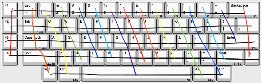
I’ve been planning a handwired build for quite some time, and we’re now in the final stages (just waiting on plates and a couple loose ends!) and I had a couple questions about row/column wiring. A diagram for my layout is shown below:
With this current layout, it would be 17 rows and 5 columns. That would require 22 pins on a microcontroller. I still haven’t quite picked out a microcontroller, (though, the Teensy 2.0 is probably my biggest consideration at the time) and I was wondering if:
A: there was a different, better way to wire
and B: what microcontroller you’d recommend for wiring as such.
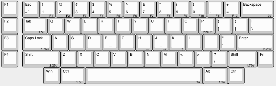
I plan to use a 24wire ribbon cable and a DIP connector to solder right onto whatever microcontroller works. If you guys have any ideas to improve my wiring, below is a diagram with no wires on it.
Thanks guys! Any help is greatly appreciated.
1 Like
You’ve got 63 keys it looks like, so I’d say do an 8x8 matrix. Gimme a few and I’ll pull up a potential matrix design.
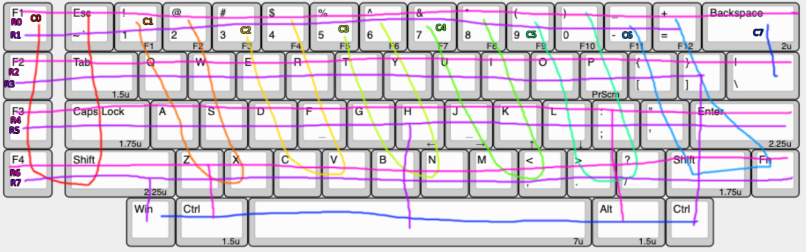
It’s not super pretty, but bear with me. Each colored “U” is a column, and each pink/purple line is its own row except where they extend down. Pink is touching the first switch on each column, purple the second one.
The easiest explanation is it’s like you’re taking every second column and stacking it down under the previous one to make a matrix that’s closer to square, since a square is the most efficient area coverage given a number of rows/columns.
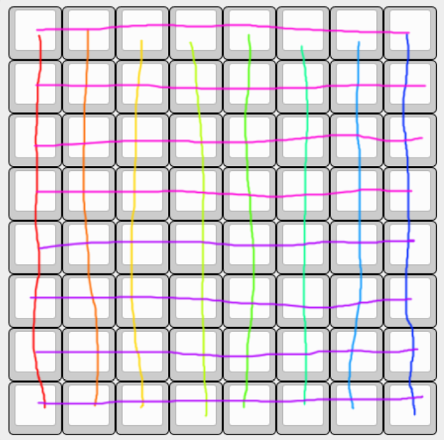
This is also what you’ll be telling your firmware the electrical layout is for mapping. It gets easier to read if on each switch you add what row and column it is like your F1 would be R0C0 and something like A would be R4C2. Also don’t get caught up on the U shape of the columns I did, it’s better to go by the row number first.
Some people would call this a “duplex matrix” but I don’t like that term because it doesn’t mean anything.
Even a ProMicro should handle 16pins of input depending on what else you’re wanting to add.
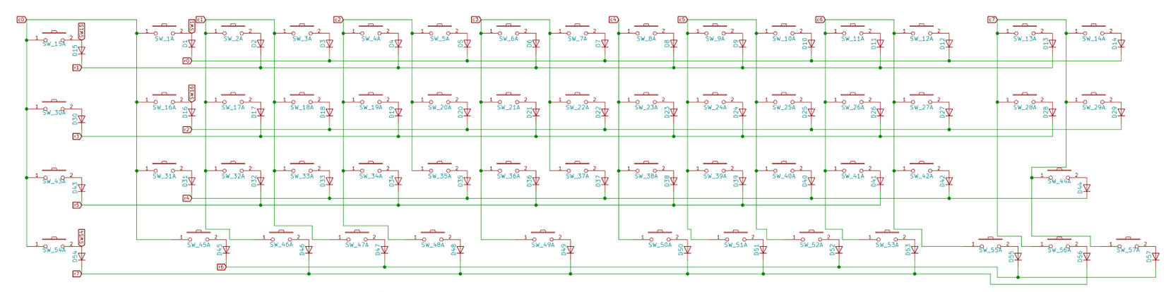
For an example, here’s the schematic on a commission PCB I did using this same methodology.
Updated with row/column denotations on the first image.
1 Like
Wow. This helps a lot. Like a wicked amount. I’m definitely wiring like this. Thank you!