I’m in the market for a macropad. Preferably 3x3, and it’s gotta be programmable. Hotswappability isn’t a definite must, but it would be super nice. However, I have no idea where to start: there are soooo many to choose from. What’s your recommendation? I’ve heard good things about custom-made ones with Arduino Pro Minis, and I’ve also heard the name BDN9 thrown around a bit. Thanks!
2 Likes
BDN9 is a nice little pad for the price and what you get. Rotary encoder support, no diodes, “socket” Pro Micro footprint, and SMD RGB footprints; all neat stuff. The PCB itself is super clean and just feels nice to look at. About my only complaint is that if you’re using MX switches and no middle layer then there’s a little bit of sideways movement possible due to the Alps support in the plate, nothing that a couple bits of hot glue can’t fix or just making sure to get a middle layer. Overall I think it’s a nice little kit and it’s given me some ideas for improving some of my designs down the line.
1 Like
I like the butter stick from @qlavier
Just handwired a 4x4 (first full project including case) with Teensy 2.0, Ponoko acrylic sandwich case and Zeal purple switches. Running QMK. Build from scratch is very satisfying if your open to that.
@jbcbrett How difficult is handwiring nowadays? I’m still new to the hobby, but eventually I want to handwire something (also, I haven’t springswapped any switches yet  )
)
For the record I’m writing this answer to myself and my knowledge level 7 weeks ago before I found answers. For all I know you’re a mechanical engineer.
Soldering is a snap. The beauty of handwired projects is you can cut your teeth with a few switches, a Teensy, solder and soldering iron just to get a basic understanding. And to make sure your development environment (computer, QMK installed, compiling and flashing) is operational.
Keebtalk is Awesome
Also you’re in the right spot. Everyone here is VERY HELPFUL! I was looking for a resource to help me create a custom hand wired board and found Keebtalk this July. I had never touched a soldering iron. Didn’t know a single fact about keyboards other than I had a favorite that I couldn’t use any more due to it’s size, QMK software, switches, switch plates etc. etc. Seriously I knew nothing.
Strip An Existing Mechanical
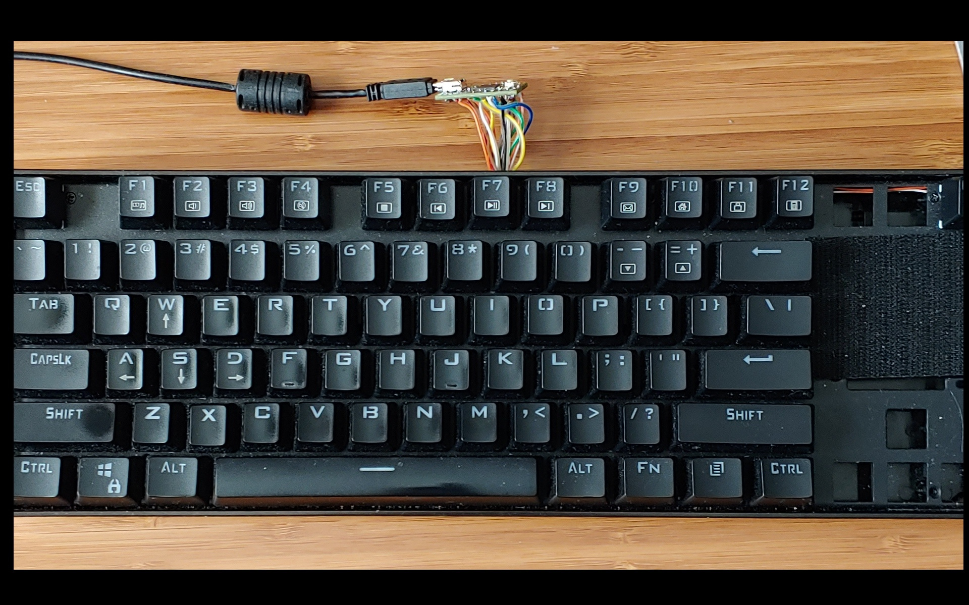
My first mini project was taking a cheap mechanical keyboard I had bought about a year ago and stripped the PCB and keys off it, wired a Teensy to it, programmed it with QMK and it’s been great. It’s not pretty but it allowed me to learn and build my first programmable keyboard for about 16 bucks…the price of a Teensy.
Yes that’s really the matrix wires sticking out of the back of the keyboard and attached to Teensy. Wasn’t going for an award, just functionality.
Macro Pad
The problem was I wanted to run macros to navigate back and forth between desktop apps for specific work projects I have and managing those macros with my daily board was a pain. So I decided to see if the keyboard success could be duplicated on a macro pad.
Use What’s Available
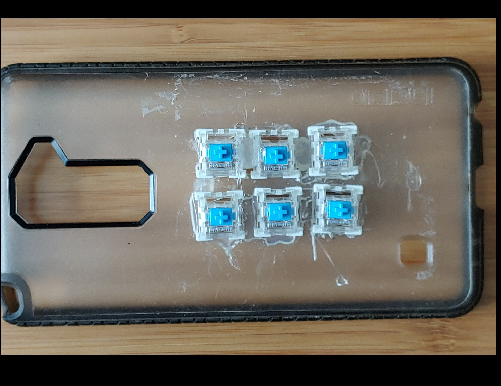
Took an old cell phone case, cut 6 holes in it, wired in a Teensy, programmed it and I literally used that for a couple weeks.
Custom Case
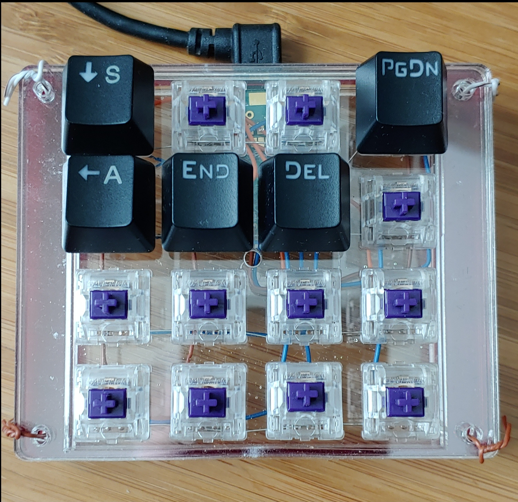
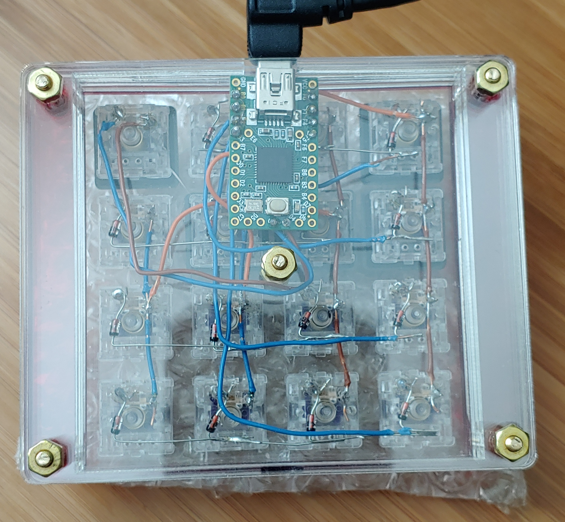
Once I knew a macro pad was just a small keyboard, I had a custom sandwich case built by an acrylic laser cutting house and I’m up and running. The case design will not win any awards and I haven’t completed it yet but it works and does exactly what I need.
Still have to get screws, a standoff for that hole you see in the middle and a couple of other things…maybe some keycaps but it works.
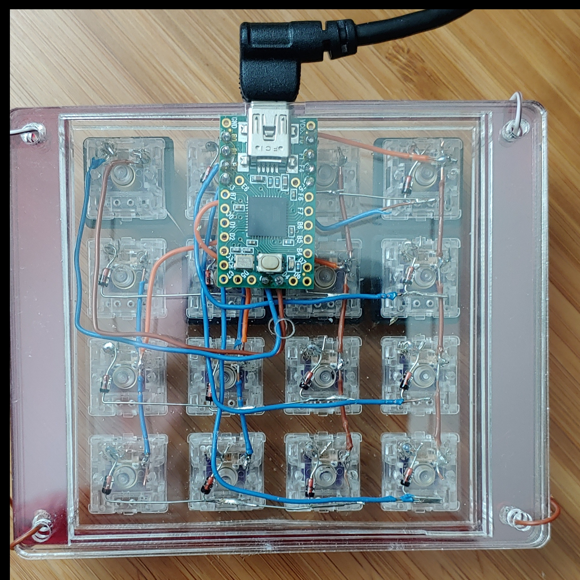
There’s really only 15 switches in the matrix on this. I like to have a mechanical switch for resetting/flashing my boards so the switch in row 0 (zero index), column 3 (physical key 4 from left) is for flashing the macro pad. One side of the switch is wired to the GND pin and the other is wired to RESET pin on the Teensy.
Notice the 2 solder points/wires immediately below the reset button on the Teensy. Since I can’t get to it when the case assembled, I reset using a keyswitch.
By the way you can also reset using an RESET instruction with QMK. I had run into a snag flashing my keyboard and the QMK key assignment stopped working so a mechanical reset will always work if there’s an issue with the QMK reset code.
What You Need To Get Going
Here’s what I wish I knew 6 weeks ago. A few things to get your macro pad running. Remember I’m a novice compared to others here talking about a subject I knew nothing about up until 6 weeks ago.
Development Environment (Linux, Windows or Mac.)
Get your environment installed/ready with QMK (or maybe some other I don’t know about). Obviously you can’t confirm your environment is working until you have something to program. But knowing what needs to be done should help remove some of the mystery. This means the ability to compile the QMK code, flash it (send it from your desktop/web tool to the memory chip on your controller/Teensy or other successfully). There are GUI and command line tools for this.
Teensy 2.0 or 2.0++: This is the engine that you’ll place QMK instructions on.
Switches: 3-6: One will do but it makes learning more difficult.
Soldering Iron: (I wired an entire keyboard using crappy solder that came with my crappy 12.00 soldering iron). I’m typing this on that same board and I used the same iron for the macro pad.
Keyboard Jargon Don’t sweat any of this stuff…it’s not rocket science, just unfamiliar. Don’t let the acronyms drive you nuts. The community specific verbiage is thick. Just ask someone. They’ll help.
Wiring Matrix:
Understanding the matrix will help answer some questions you might have. The matrix, through soldering, is going to connect your switches by row and column. Those rows and columns will be connected to the Teensy and your build environment (QMK software) has instructions allowing QMK to understand which physical switch is located at row 2, column 1.
How Many Matrix Pins Do I Need?
Cell phone case macro pad used 5 pins on the Teensy. 2 rows + 3 columns = 5 Teensy pins.
New macro pad is a 4X4: 4 rows + 4 columns = 8 Teensy pins.
Never intended to run on like this. Hell I may be violating some rule in Keebtalk and you’ll never see this post, but a bunch of stuff came to mind while explaining this.
If you do see this, and it helped, let me know and I’ll take you step by step through what I did (or at least what I remember), the resources and tools I used including vendors. Just know if you need help and I can help, let me know. Good luck!
5 Likes
I’ve always needed to learn this, but I’ve never been able to get myself to do so. Where would you go for advice about learning?
So, let me get this straight. Is the case custom-printed, or did your order it from somewhere?
This one is a really novice question. Matrix pins are the holes on the Teensy, yeah? Thanks for the lengthy post: definitely got a foothold now because of that. Handwiring doesn’t seem as bad as I initially thought it was.
The only rule you’re violating is how awesome this post is! But that rule is meant to be broken.
2 Likes
There are plenty of good beginners’ guides online! This one is pretty detailed: How To Solder: A Complete Beginners Guide - Makerspaces.com
You can also e.g. watch a keyboard build stream VOD on youtube to get a general idea of how experienced people do it. Of course, both of these examples are going to be mostly aimed at through-hole soldering (using a PCB) which is easier than hand wiring, but you can also look up handwire-specific videos like this: https://www.youtube.com/watch?v=zY2k75eWrLQ&feature=youtu.be&t=407
And, as jbcbrett said, always feel free to ask about anything you don’t understand! Handwiring is far from my own area of expertise but there’s no lack of experience between the users here in whatever you’re looking to do ![]()
Thanks @cijanzen, hopefully it will help some people.
This 5 minute video from Collin’s Lab, removed any self doubt about soldering I had. When I first saw this, I didn’t even have a soldering iron. Remember, many cautions you’ll hear in how-to soldering videos revolve around applying too much heat to the PCB (printed circuit board). The macropad in this example does not have a PCB. One less thing to worry about.
For my application the case was not printed it was cut, and I did order it from Ponoko.com (acrylic laser cutting vendor).
You’ll often read comments from people talking about printing cases, enclosures, accessories etc. They are using a 3D printer to do so. I have zero experience here but these machines use a filament/plastic type printing material versus a traditional desktop laser printer that uses ink as an overly simplified explanation.
I designed (not a designer, not a CAD guy, this is all new to me) the layout (4X4 / 16 square holes for the switches to snap into. Cherry type switches require a 1.5mm “switch plate” so when you push the switch into the plate, each switch snaps into place. The advantages of acrylic is it’s cheap. This macropad case, custom cut, delivered was 35.00 bucks…amazing.
You’re welcome…glad to help!
Matrix = result of soldering keyboard rows and columns together.
Teensy Holes = referred to I/O pins. I/O means IN/OUT.
Matrix Pin Requirements = the number of required Teensy I/O pins is calculated by taking the sum of device rows & columns. 3X3 device has 3 columns and 3 rows (3+3 = 6 pins required). 4X4 = 8 etc.
Handwired (macropads and keyboards) is BETTER = complete freedom for you. Don’t need someone to design a PCB based on your requirements. Once you understand handwiring and how to design a switchplate (optional because you can use anything stable enough to hold switches in place) for production, you can literally make any custom keyboard you want. Switches + Teensy/controller + plate equals custom device.
Industry Speak
This community has many methods to communicate the same thing. It’s not a bad thing but to the uninitiated it can be painful. If you don’t know…Google it. If you don’t get an answer there…ask. This is what I did and the Keebtalk community has answered many of my questions! I got answers to questions I didn’t even know to ask.
Switch Pins (only 2 for soldering)
Keyboard switches have 2 pins that are soldered. This is part of creating a matrix. This is how the device knows you want to type the letter A or W. The switch that the letter A is assigned to is “usually open” meaning no activity. Just like the light switches in your house…“usually open” so the room is dark. Press either switch and you get either an A or light. Simple right?
Keyboard switches have other physical attributes described as pins that have nothing to do with soldering. Plate VS PCB Mount Switches.
Plate mount switches: Often referred to as 3-pin. Two pins to solder and a single plastic protrusion on the back side of the switch. No idea what purpose the 3rd pin serves but I’m guessing it’s a manufacturing thing.
PCB mount switches: Often referred to as 5-pin. Two pins to solder, a large single plastic protrusion on the back side AND two smaller protrusions on the back side. So 3 plastic pins and 2 soldering pins. These two smaller protrusions help keep your switches straight when soldering to a PCB. Image trying to keep your switches straight when soldering them to a PCB (without a switch plate to keep them straight). Chances are many of them would be off by a degree or two.
Design Process:
- Create your layout.
- Take layout information and create case design
- Take case design information and get quote at vendor
1: Create YOUR design. Go to Keyboard Layout Editor. Up top select Preset | Blank which clears screen. Upper left drop down menu next to Add Key, choose add 10 keys. Delete one (left mouse click press delete) key leaving you with 9 for your 3X3 macropad.
This tool is awesome. Left mouse click drag around (entire key) multiple keys to select and position them using your arrow keys.
Once your device is designed, in the lower half of the window click “raw data”. Select all this content and paste into TXT file on your computer. To return to this design anytime in future, paste content from TXT file into raw data tab. Go to step 2.
2: Plate & Case Builder to create CAD DXF File for Laser or Water Jet Cutting. Don’t worry about the process, focus on preferred material. In my case I used Ponoko.com. I don’t know this company well. All I can say is my first experience was good.
Brass Bolts
There’s been progress since last posting. Replaced the strands of wire holding the plate layers together with brass nuts and bolts. The middle of 5 bolts is a standoff which supports the middle of the switchplate when keys are pressed. At only 1.5mm, the switchplate is somewhat fragile. Had I known what I was doing initially, aluminum or stainless would have been chosen for the switchplate.
See The Layers Of Acrylic?
For reference the very top layer is 1.5mm thick. The red layer below it is 3mm thick. At 1.5mm, your switches will securely snap into place. This is what Ponoko created for me.
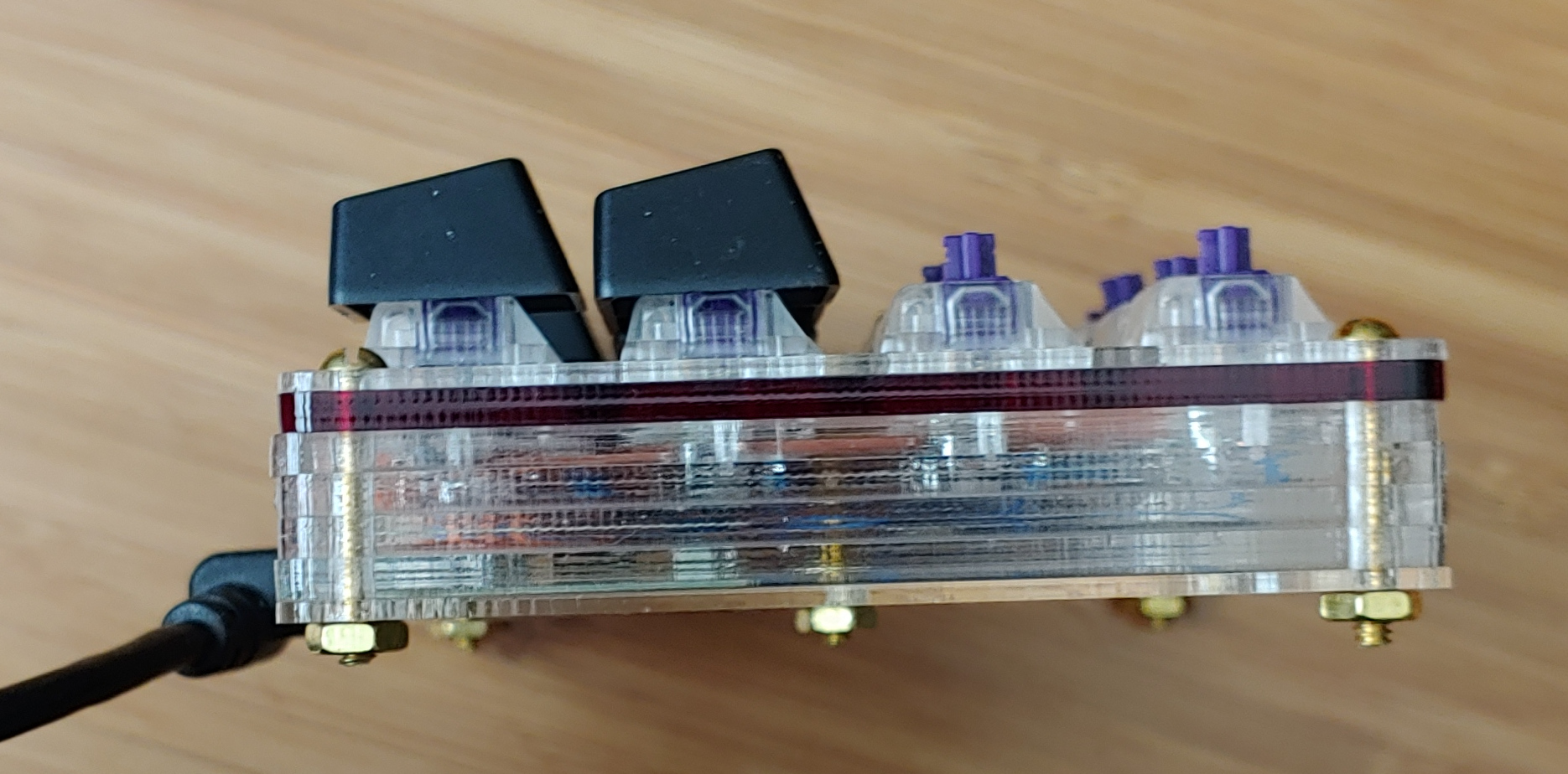
Well…why not use a switchplate created from 3mm stock? The switches don’t snap into place and most likely need to be glued. Not a good option on a clear acrylic design.
Overall the design is this: The switchplate with the switch cutouts, 6 perimeter layers (one being red by choice) building depth for the switches to fit, then a bottom layer that acts as the bottom of the device. This is referred to as a sandwich design and you’ll see an option for selecting this setting in the Plate & Case Builder.
3: Wiring Matrix Visual from KBFirmware. KBFirmware will serve multiple purposes depending on your project.
- Handy switch matrix layout visual which is helpful for keyboards.
- Source files (SUPER helpful when creating a new handwired project) to be used with QMK.
QMK Configurator from what I can gather (again not an expert) is primarily for use with boards that are already represented in the QMK keyboard layout list. The boards are somewhat or massively popular and someone has gone through the effort to make the source files available conveniently from within QMK Configurator.
KBFirmware helps, at least it did for me, in creating the source files for your custom device that you will not see represented within the QMK Configurator. Me just typing this shit makes this sound so frigging hard. It’s not…just not familiar.
3 Likes
Great page @Laughmaster…thanks.