Ergo87
This thread is to track and share my progress on the Ergo87
| Project Status | In Development |
| Project Description | An 87 key ergonomic keyboard, inspired by the Atreus. |
This thread is to track and share my progress on the Ergo87
| Project Status | In Development |
| Project Description | An 87 key ergonomic keyboard, inspired by the Atreus. |
Today I finished the first build using one of the rev1 PCBs. Throughout the
build process I learned a few things that I will take into account in the next
revision of the PCB.
The height of the board can be reduced by placing the ItsyBitsy upside-down so
that the Micro USB port is sandwiched between the switch plate and the PCB.
Doing so allows the middle plates to be only 9mm and also has the added benefit
of providing protection for the USB port.
The main problem this poses is that the reset switch is no longer accessible so
I will need to add a separate push button to make flashing the controller
easier. Jumping GND to RESET is not a pleasant workflow.
RGB underglow can be added to the board but it is a pain on the rev1 PCB. I
accomplished it in my build by handwiring the bottom row to the MISO pin on the
ItsyBitsy to free up D7 which supports PWM.
In the next revision of the PCB, I will update the trace so that row 6 is
connected to MISO and then add 3 pads to the PCB for 5V, GND, and D7 so that
adding RGB is trivial.
I received some great advice in another thread about supporting LED
backlighting and think I should actually be able to accomplish this now,
although it will be the lowest priority feature of rev2.
When I have some time, I’m going to try to prototype a 2x2 macro pad PCB with
LED backlighting to make sure I understand what I’m doing before implementing
it on the Ergo87.
Hey, wanna be friends?
That’s a nice looking keyboard ![]()
Any pictures of prototypes?
Definitely! That is actually quite similar to the last keyboard I designed called the Speedo but it looks like you’re putting much more thought into yours. ![]()
I wasn’t very happy with the thumb keys on the Speedo. I think the angles I chose were a bit too aggressive and I will dial them back again if I ever get around to making a new version. Having used an Iris as a daily driver for a bit, I think the layout you’ve chosen for the thumbs would be superior.
I do indeed have some pictures!
These are from the first build which was hand-wired
These are from the second build I just finished this morning which uses a PCB. It actually has underglow but the dark red translucent material I chose for the middle layers doesn’t diffuse the light nearly as well as I had hoped it would. ![]()
I chose angles/rotation based on the length of my thumb (from the first joint), so in theory they should fit me perfectly at least. I haven’t had the time to wire up the board yet, but preliminary tests feel very good.
That’s very nice looking ![]() Too many keys for me, but still a nice board. Utilizing R0 and R5 is great!
Too many keys for me, but still a nice board. Utilizing R0 and R5 is great!
Last night I finished adding the three features I wanted in the next version of
the PCB:
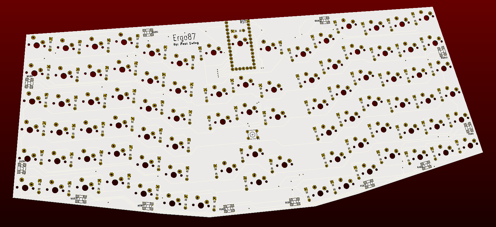
So, the back side of the PCB now looks as such:
Note the 12 spots around the edge for WS2812b SMD RGB LEDs as well as the
footprint for a B3F-1000 push button right in the center.
I decided to postpone adding LED backlighting as I think it will take me a
while to get around to it.
Today I ordered enough parts to build 5 copies:
Although the intent of the project isn’t to make money, I will likely sell
three sets of the materials as kits to recuperate some of the costs.
Prototyping is particularly expensive because of ordering in such low
quantities. Also, in some cases, such as for the PCB, it is impossible to have
less than 5 manufactured.
I likely won’t receive all of the parts and get around to building the new
version for a few weeks so I will post an update then!