Fat plates

I’ve been toying with the idea of a ~4.5mm thick plate.

I know others have done this but I haven’t seen a lot of information and/or progress. There are not a lot of custom keyboards with extra thick plates.

Why are there no more fat plates? I suspect because there are a few elements in the way.

The main reason I wanted to try to make this work is because of weight. An extra thick plate can increase the weight of a 40% keyboard by around 400 grams (0.88lb).

The second reason would be stiffness, although I’m not yet convinced about having a super solid keyboar. We’ll see.

So here is my custom plate journey:

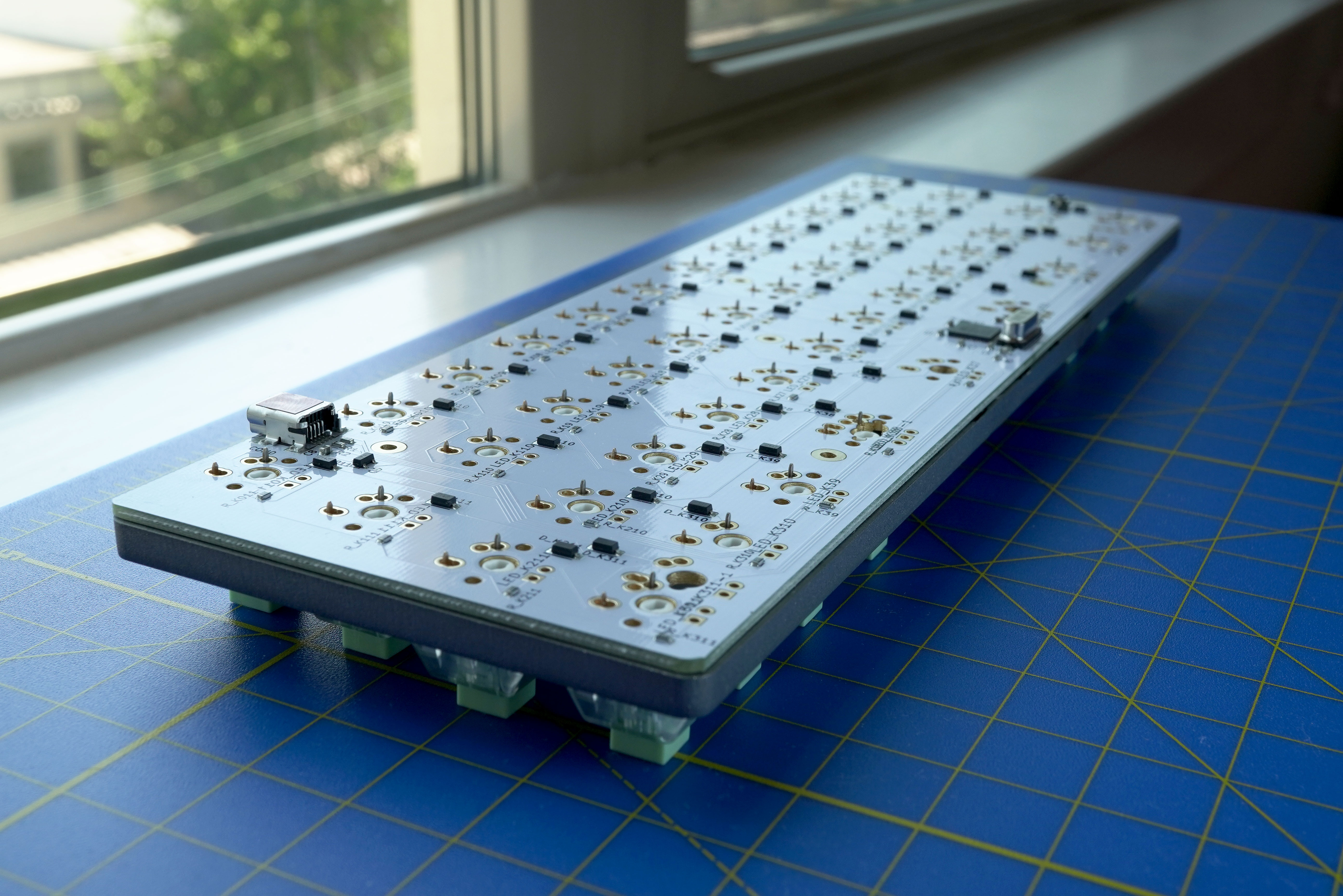
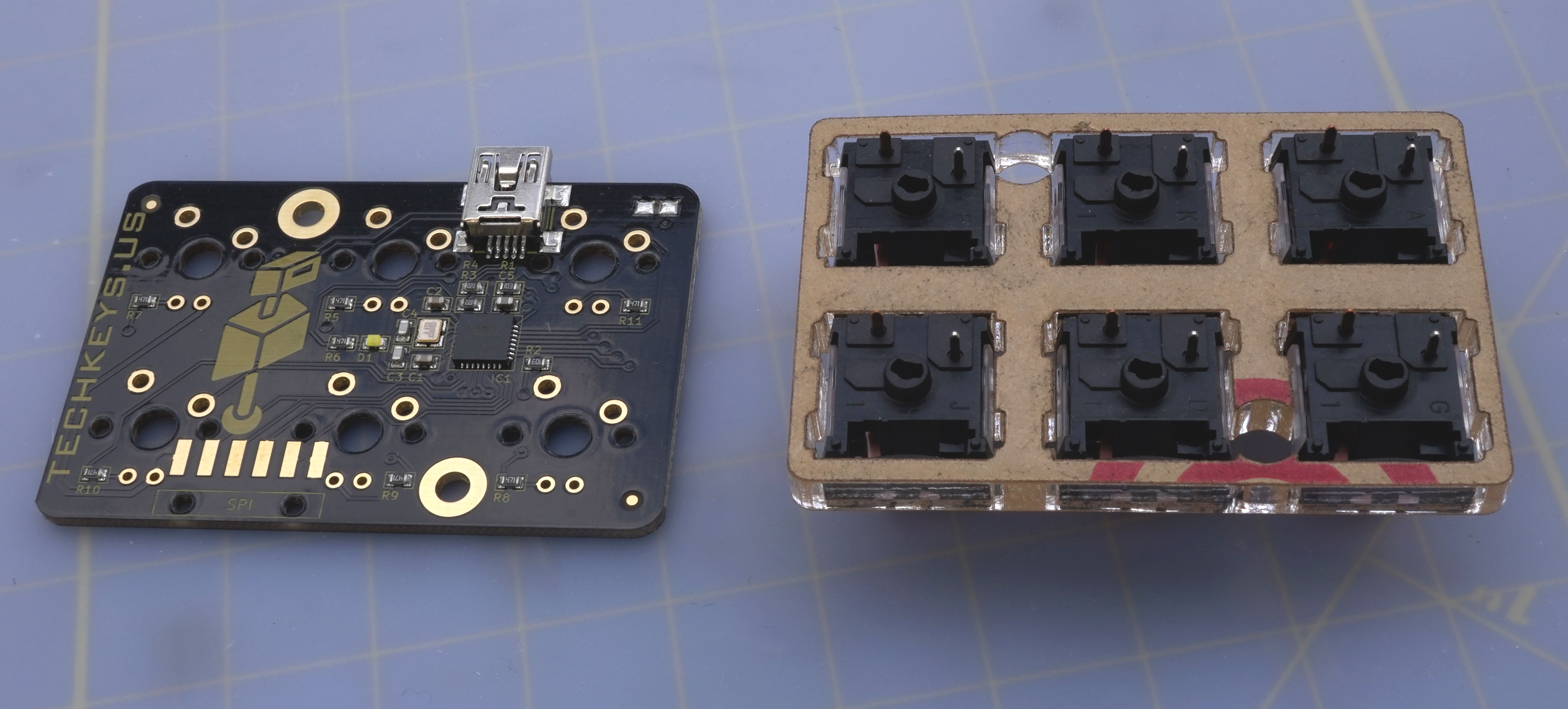
I started by using the DXF file provided by The Van Keyboards for the MiniVan Rev. 3 PCB in their site.

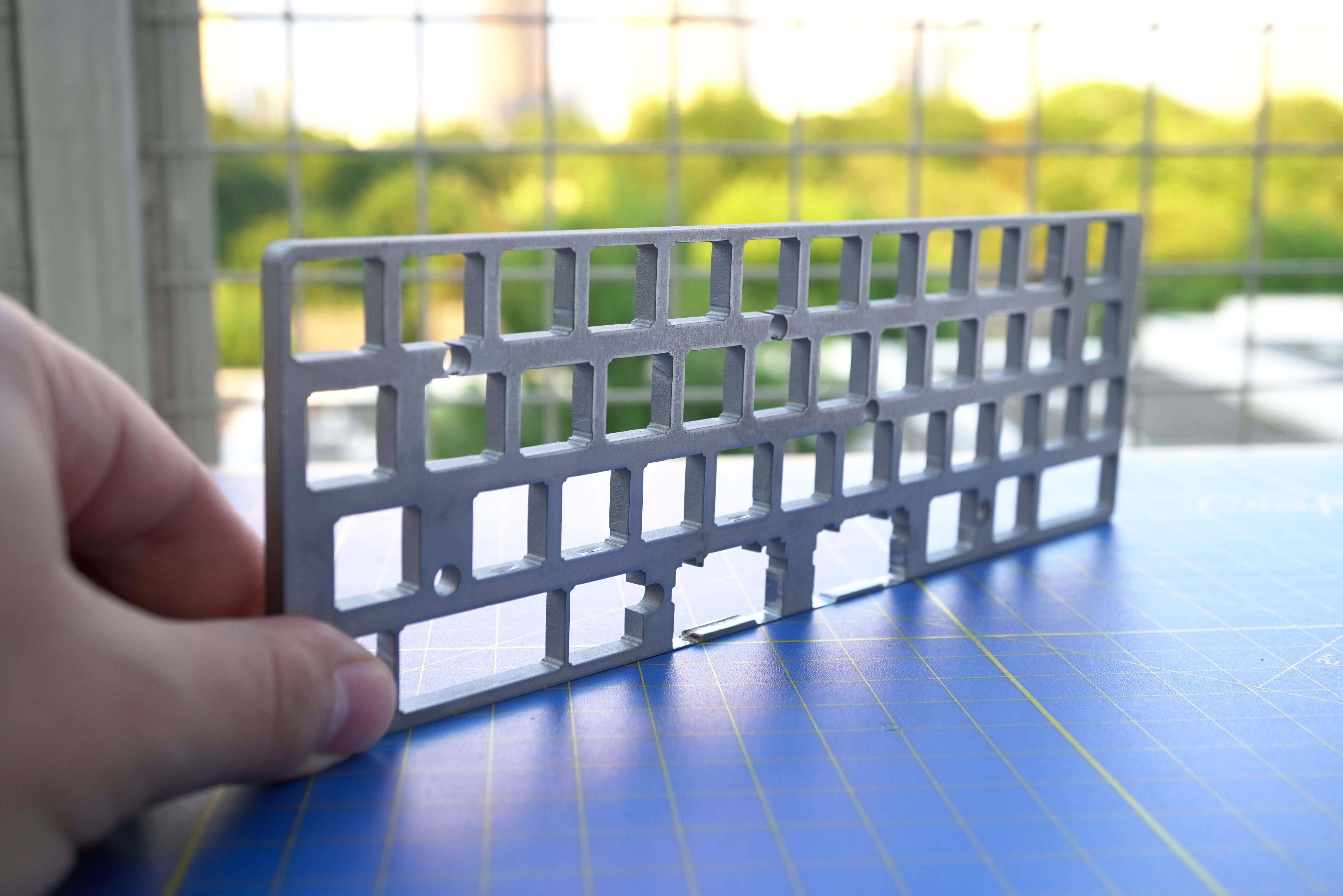
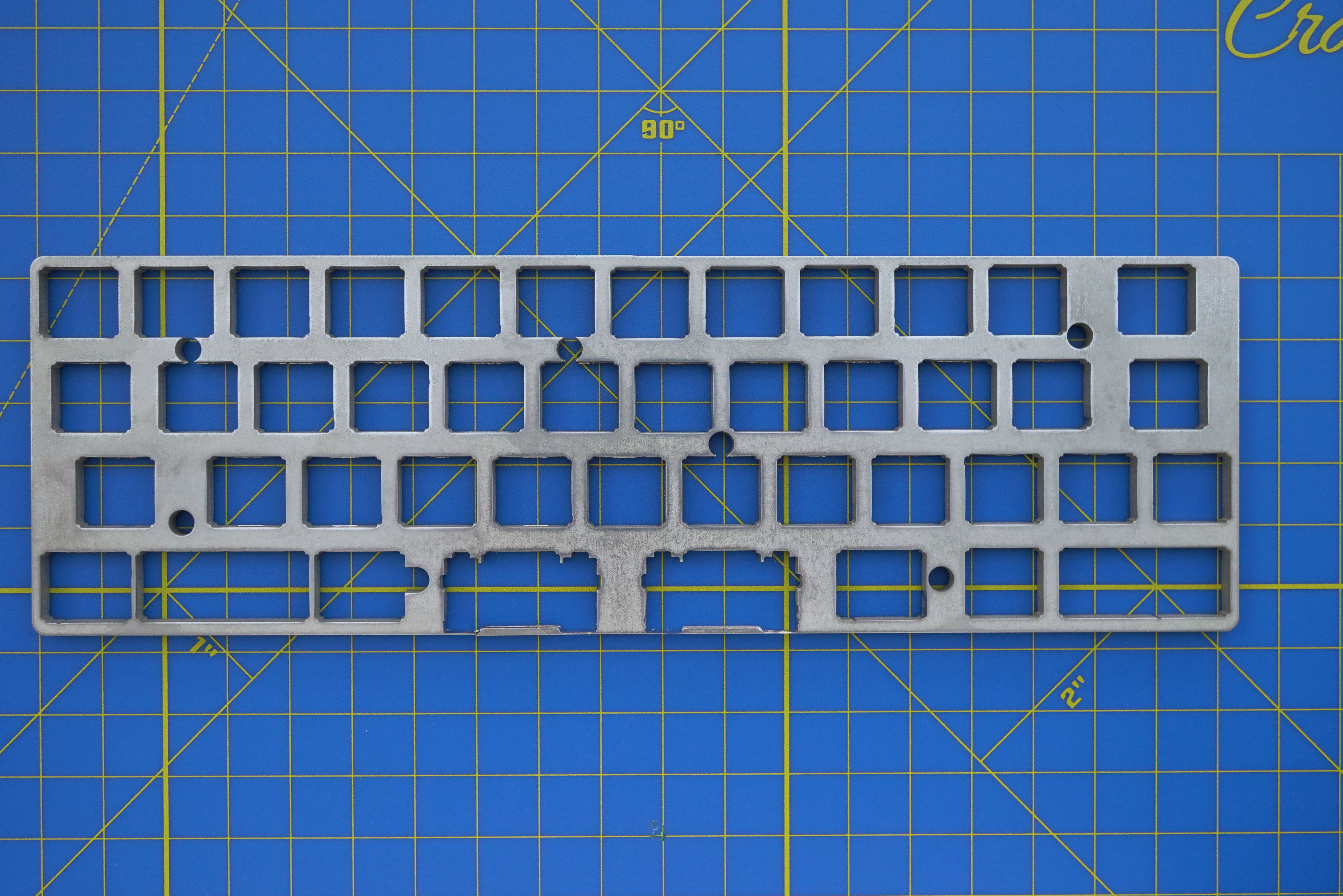
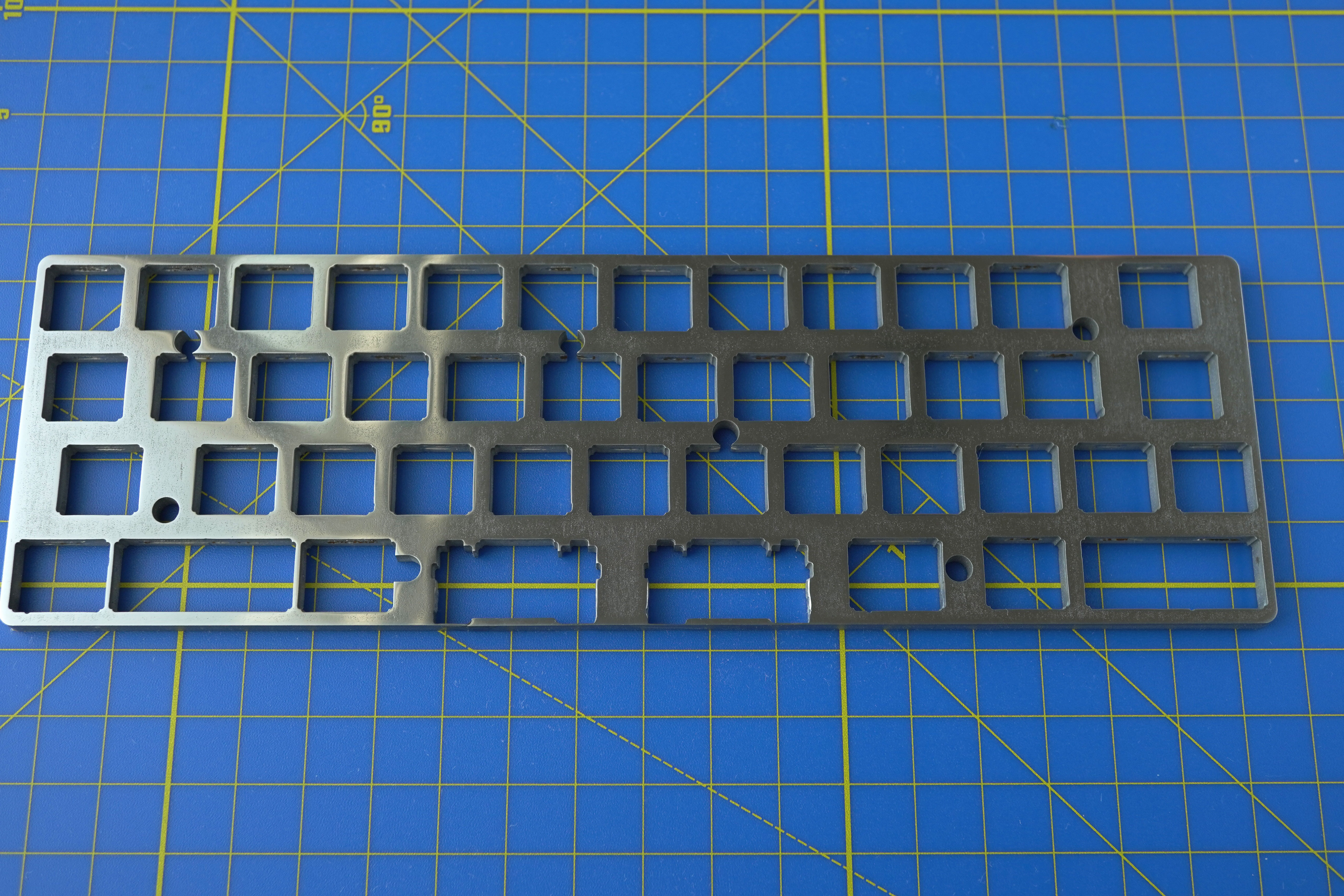
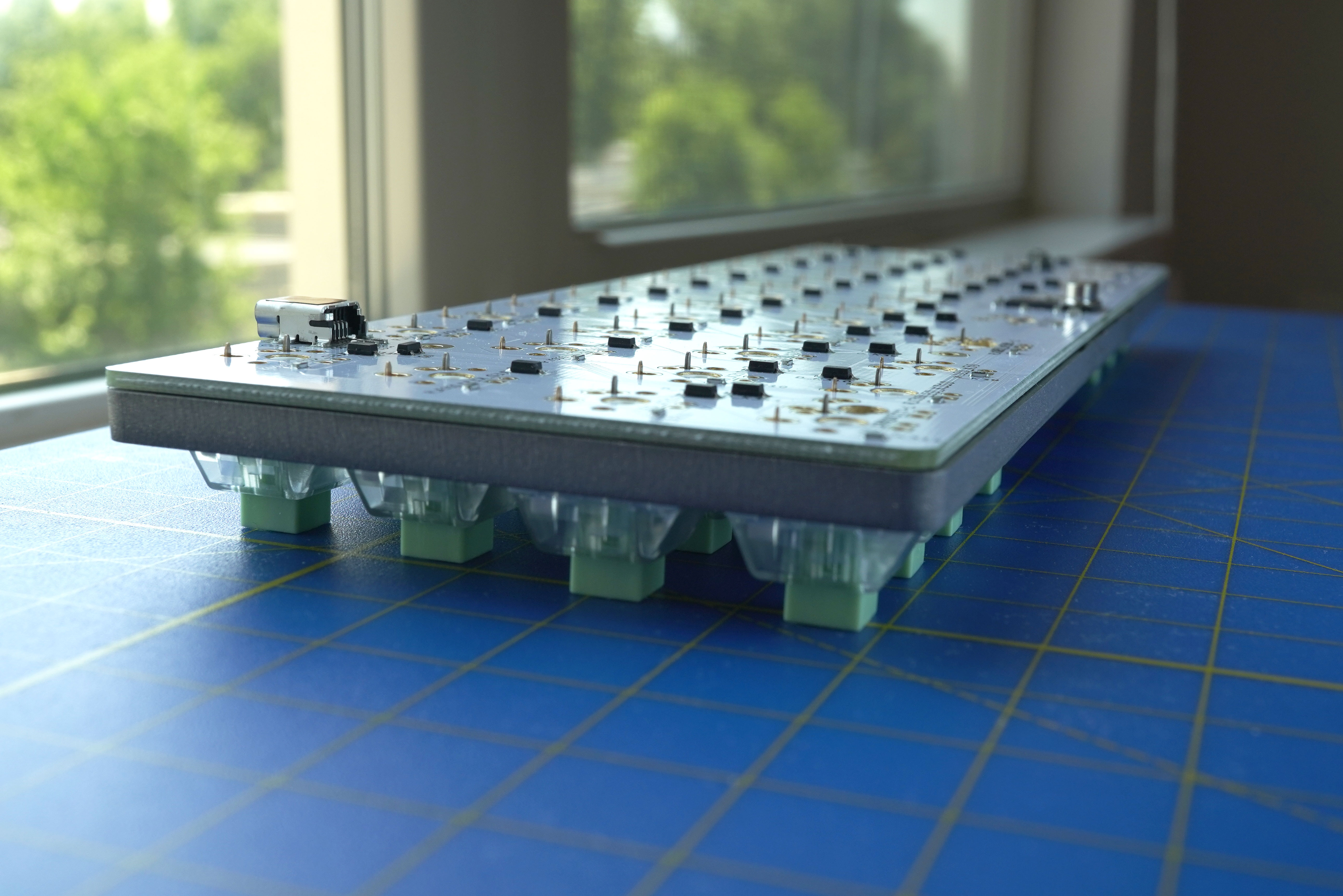
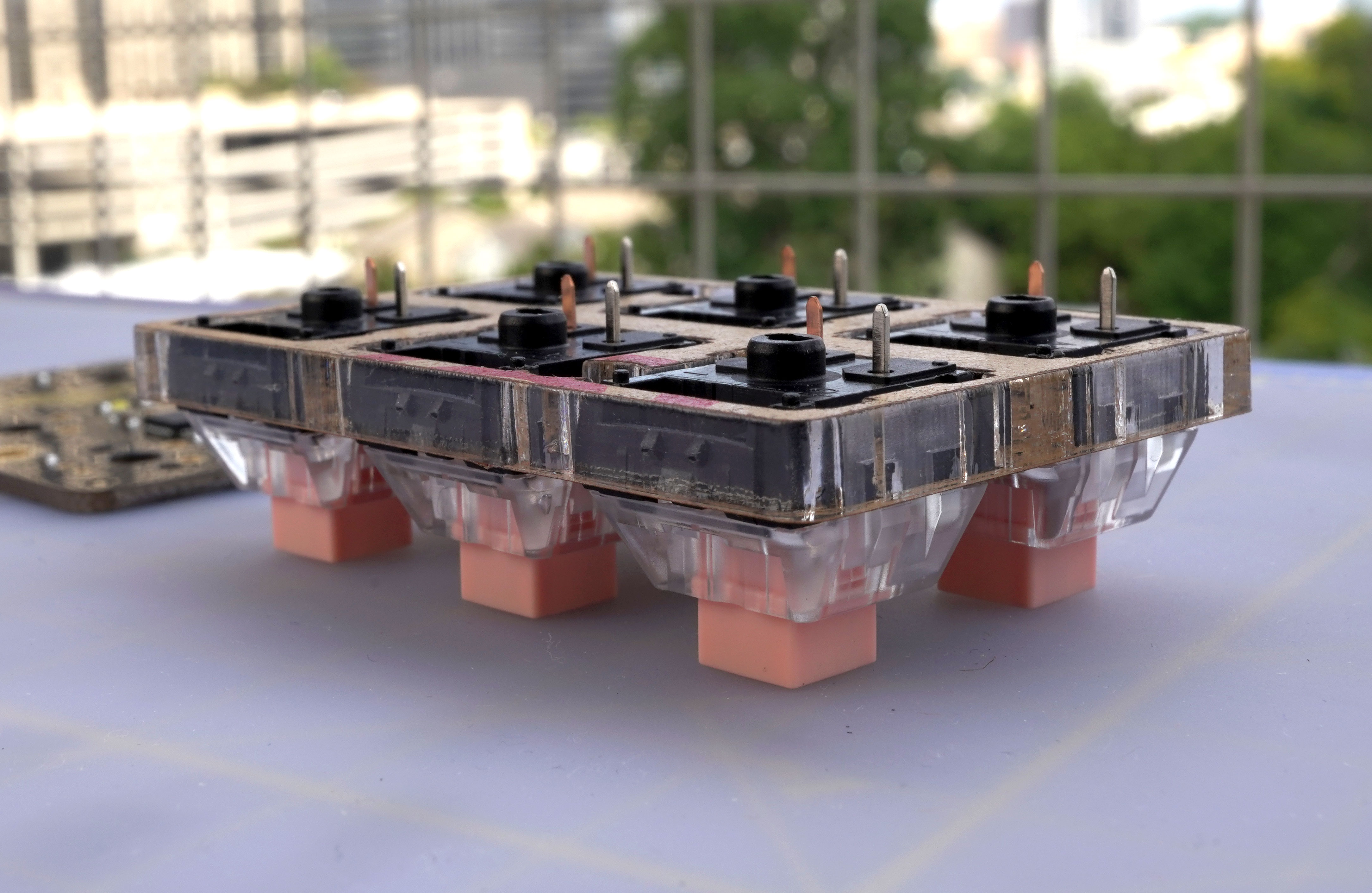
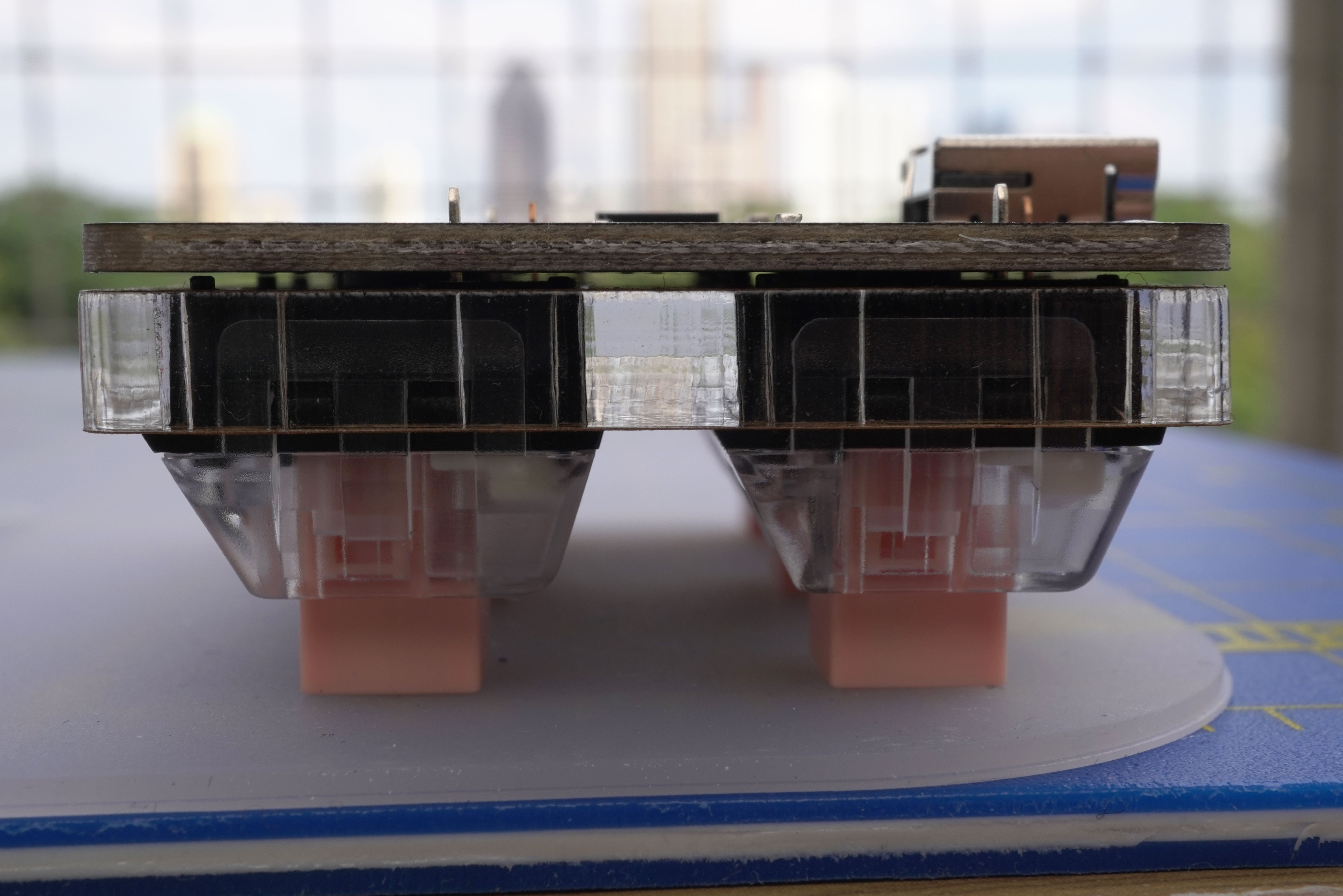
The plate was cut in 4.76 mm thick (0.1875 inches) Stainless Steel.

The main challenges of this oversized plate were:

  • Stabilizers: The DXF file is designed to accommodate PCB stabs. PCB stabs will not fit between the plate and the PCB unless the plate, or the design, is modified. Plate mounted stabs will also not work on this design.
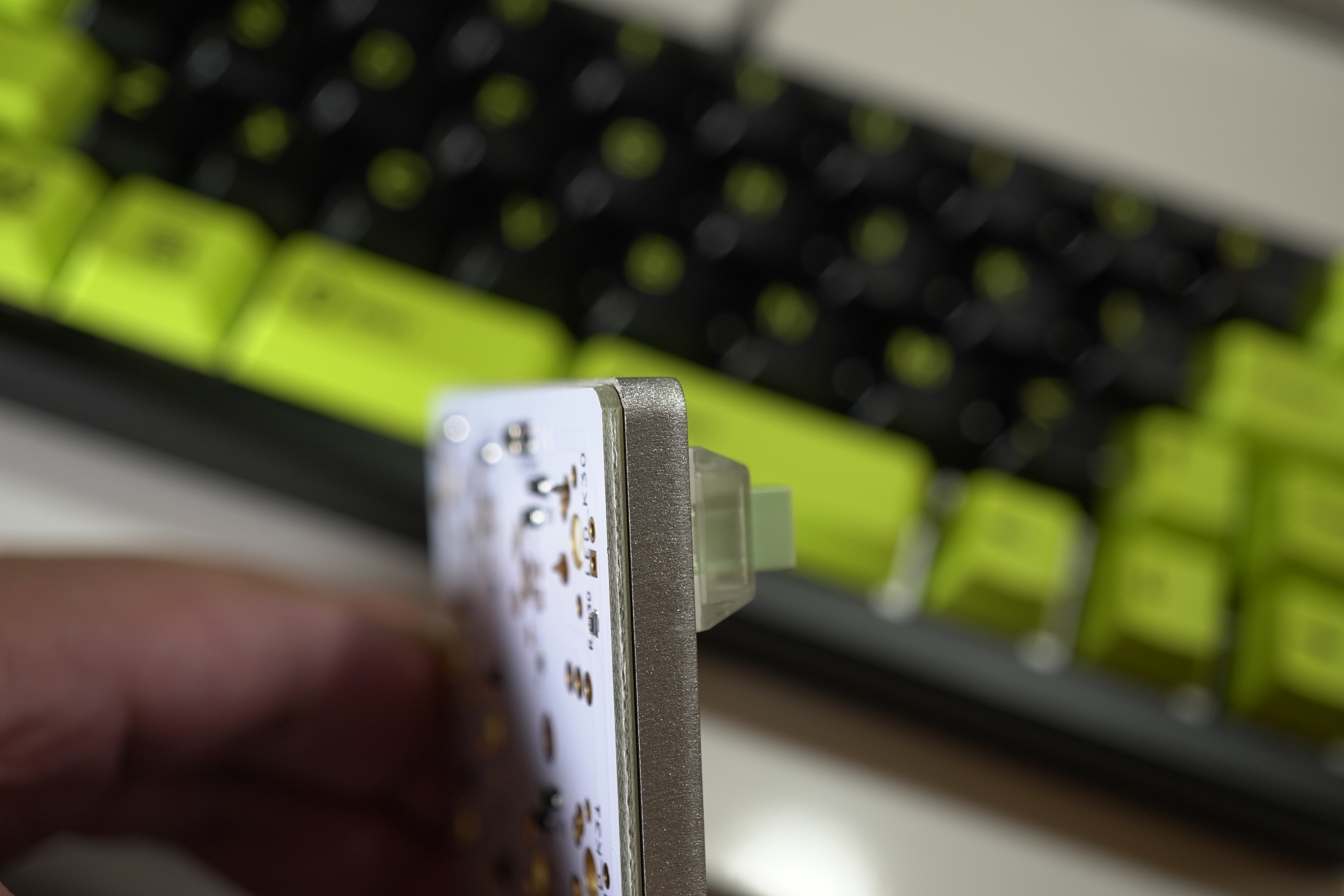
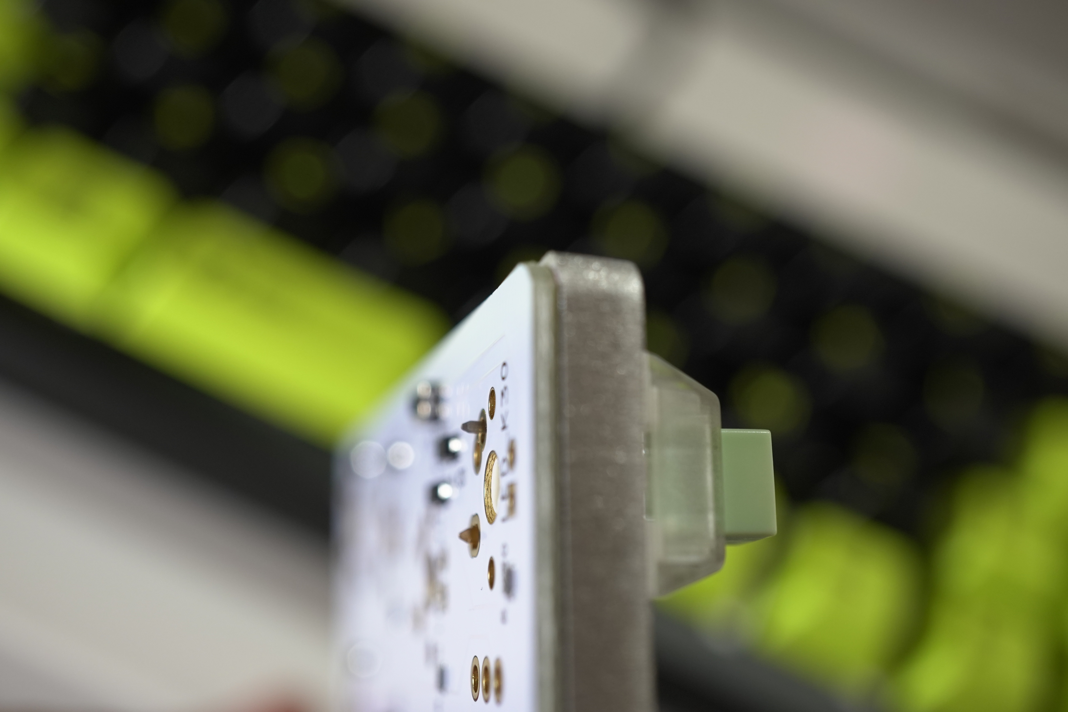
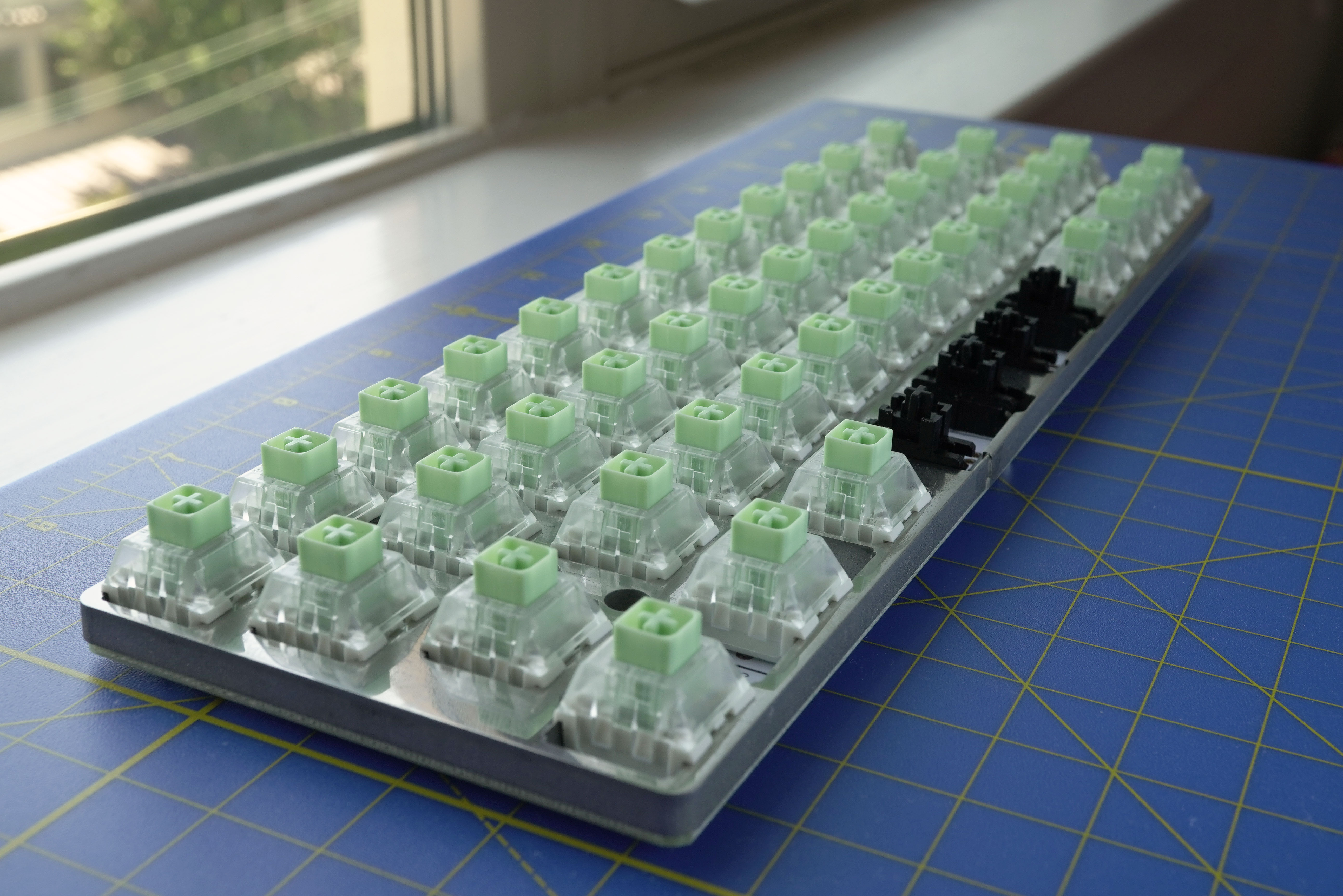
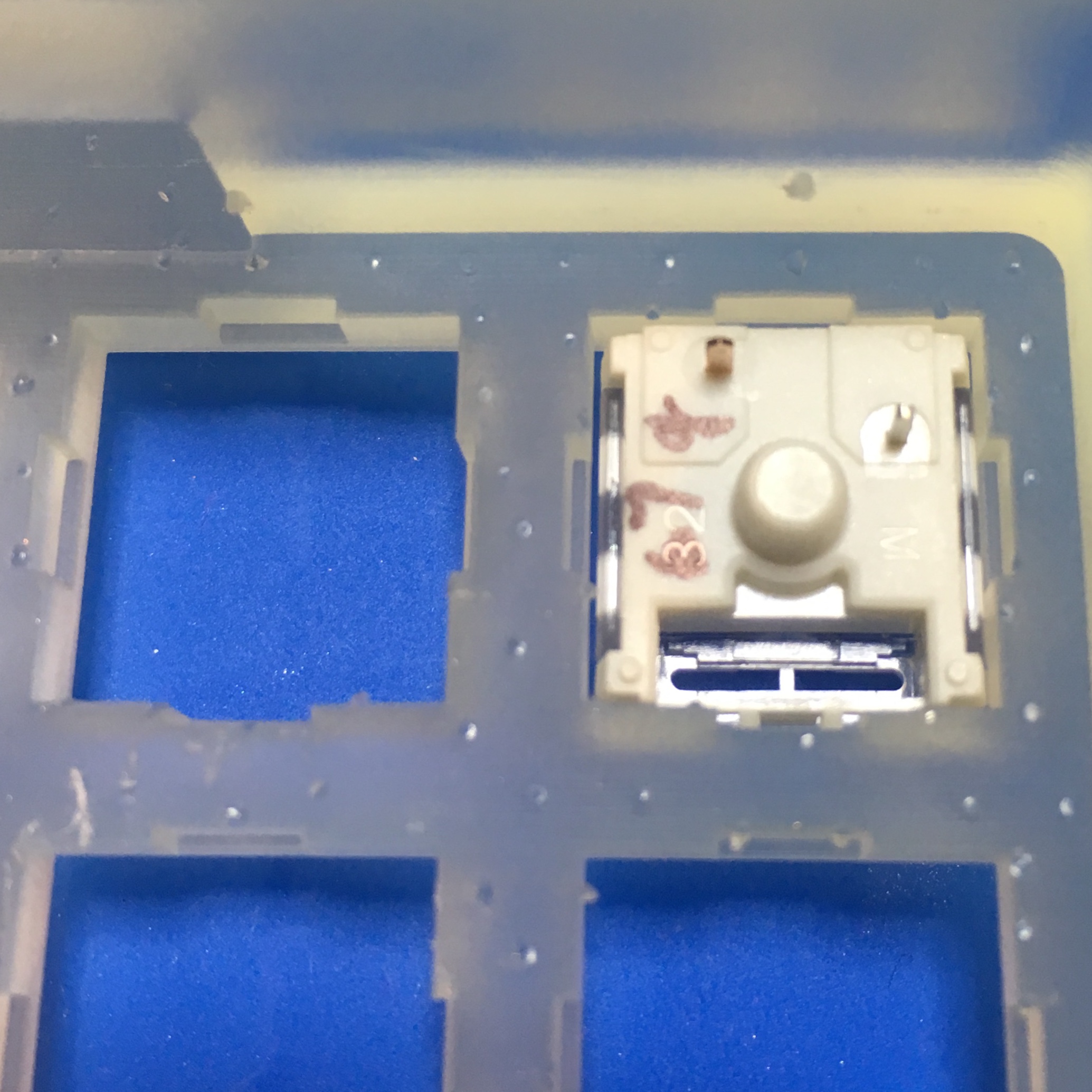
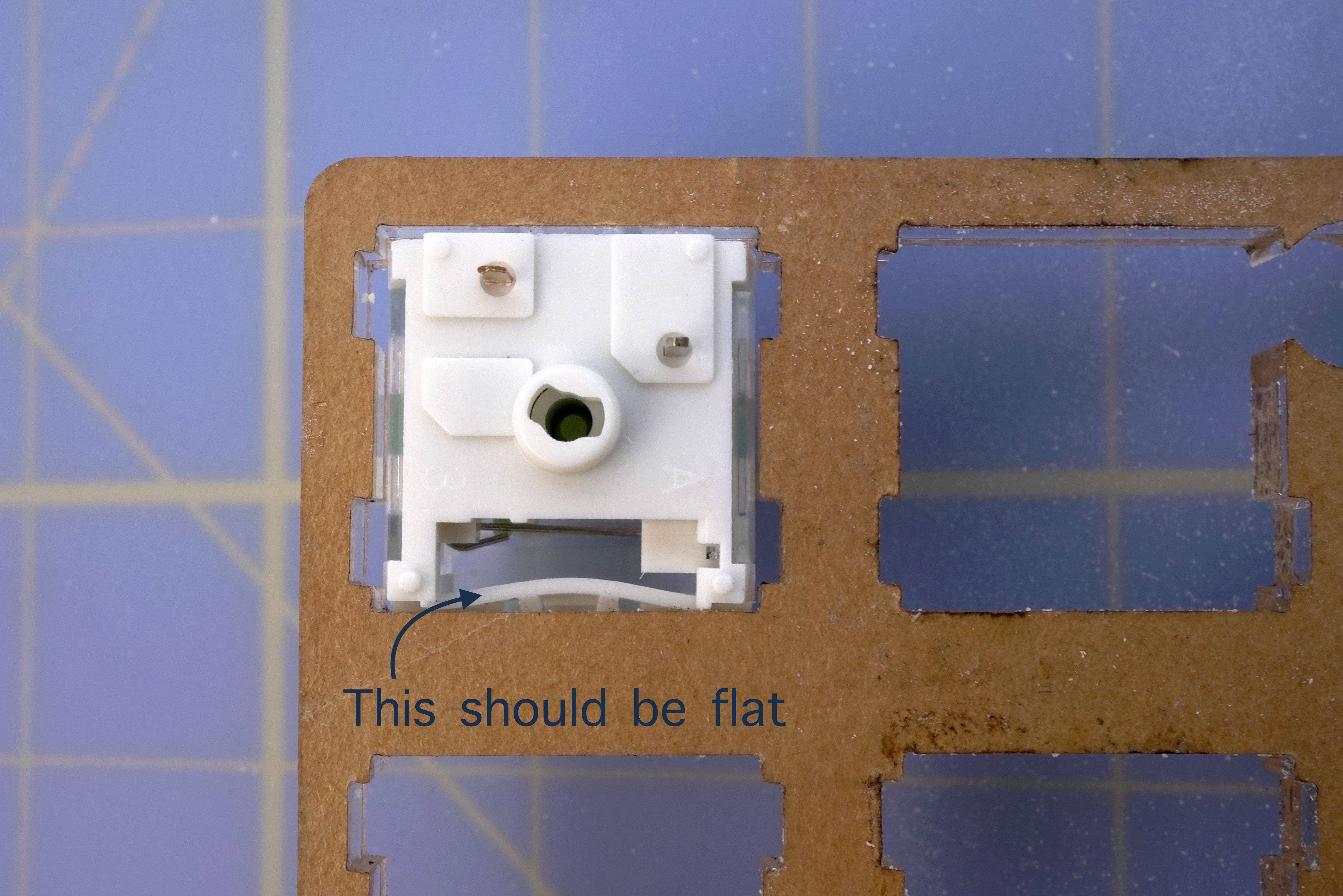
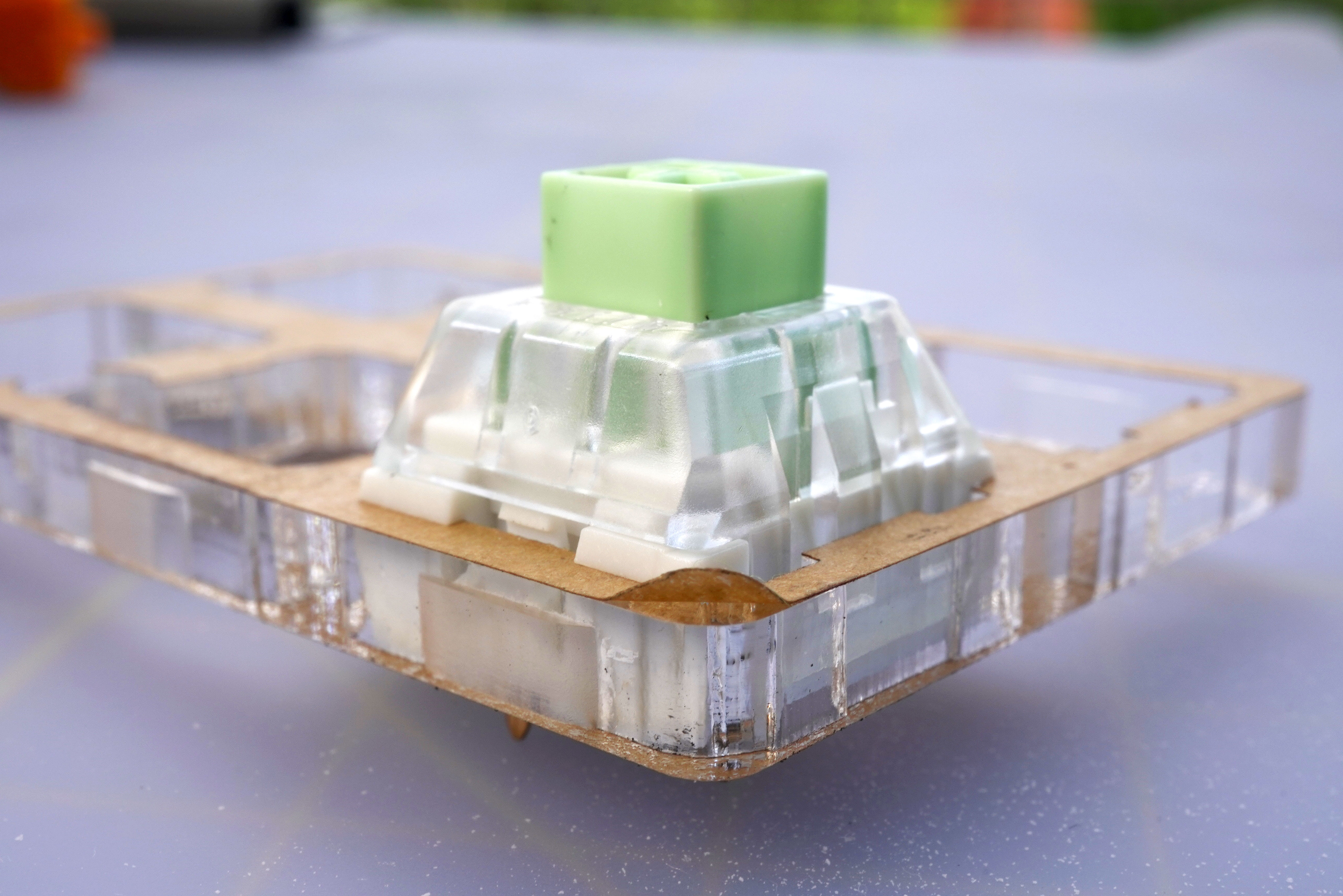
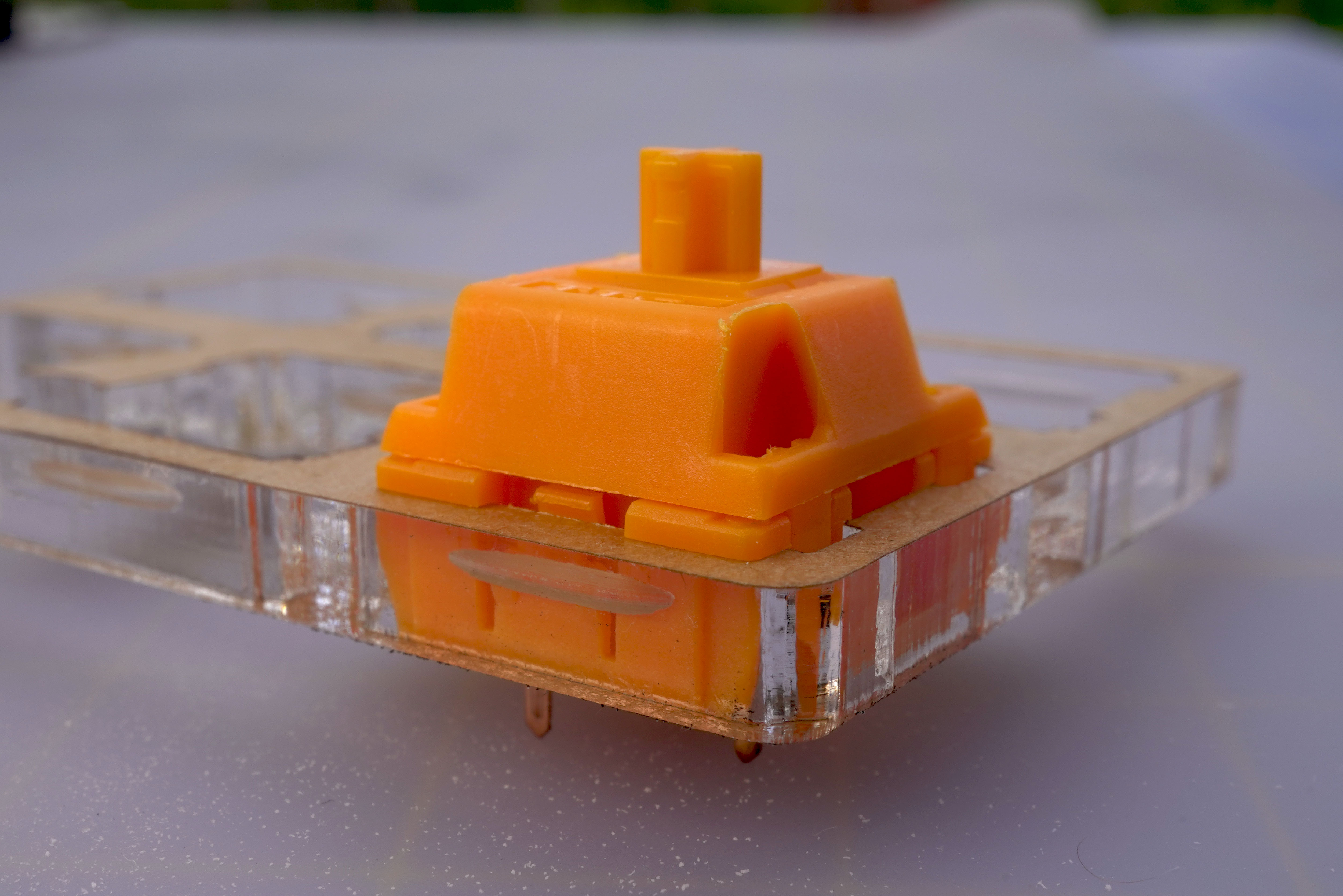
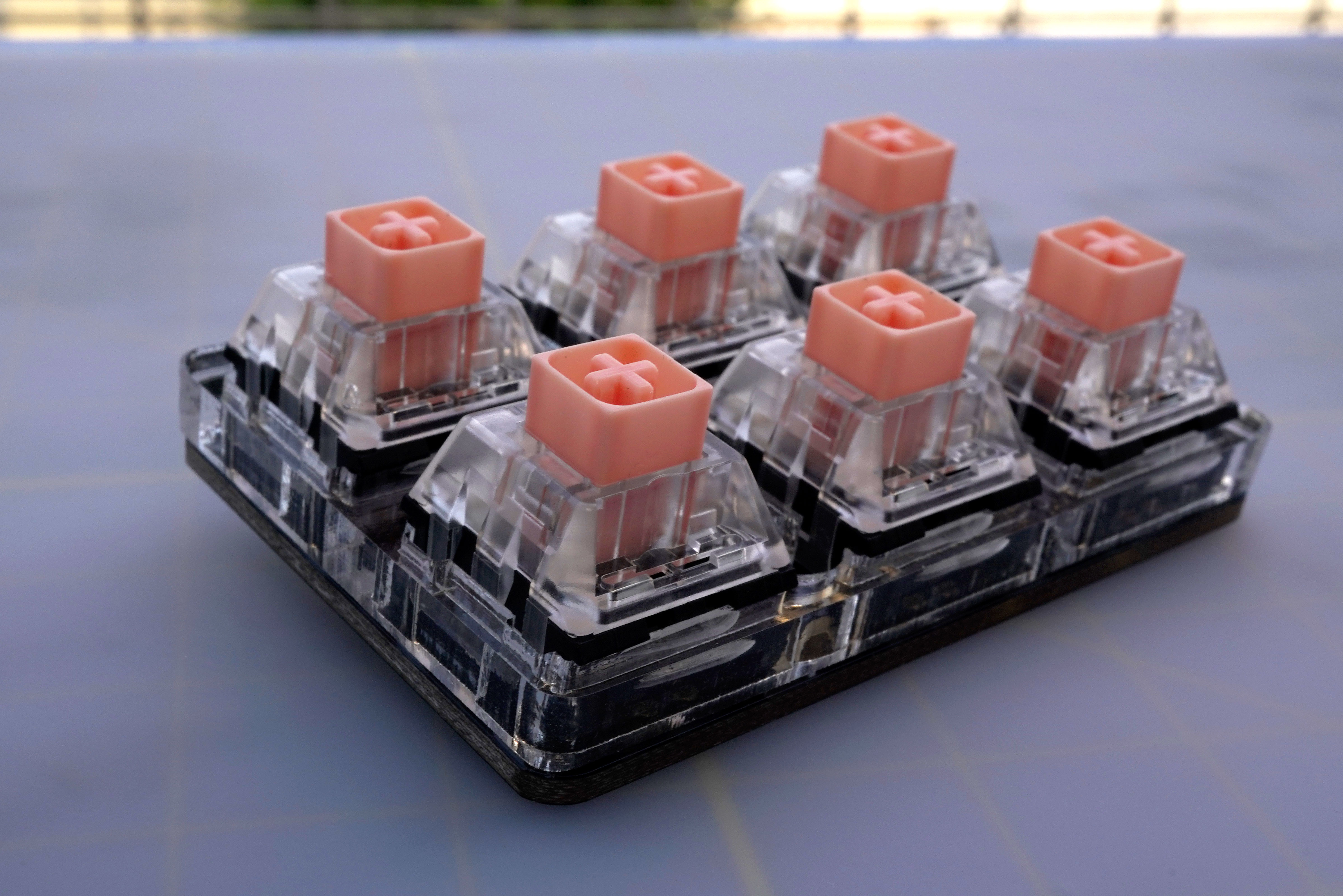
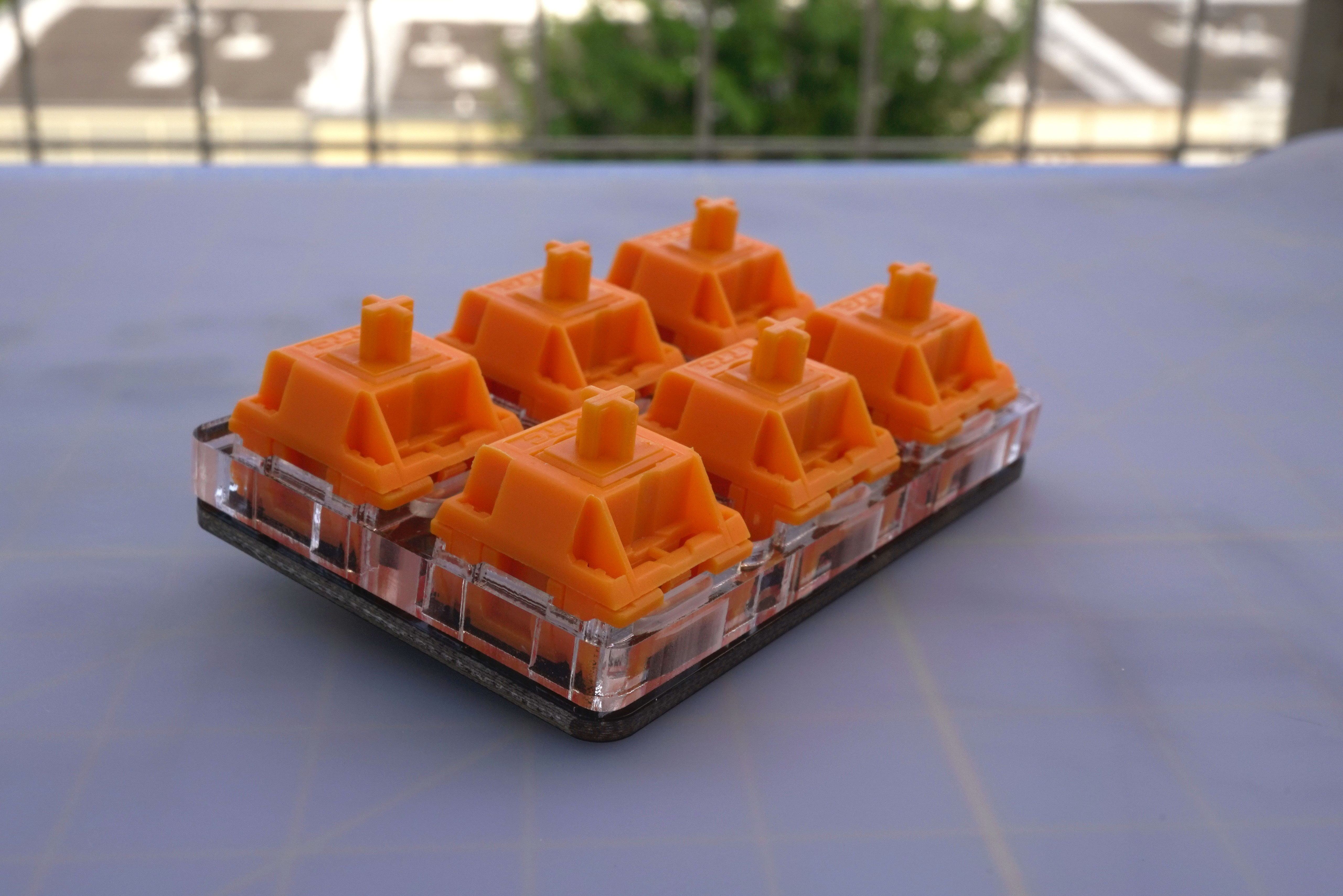
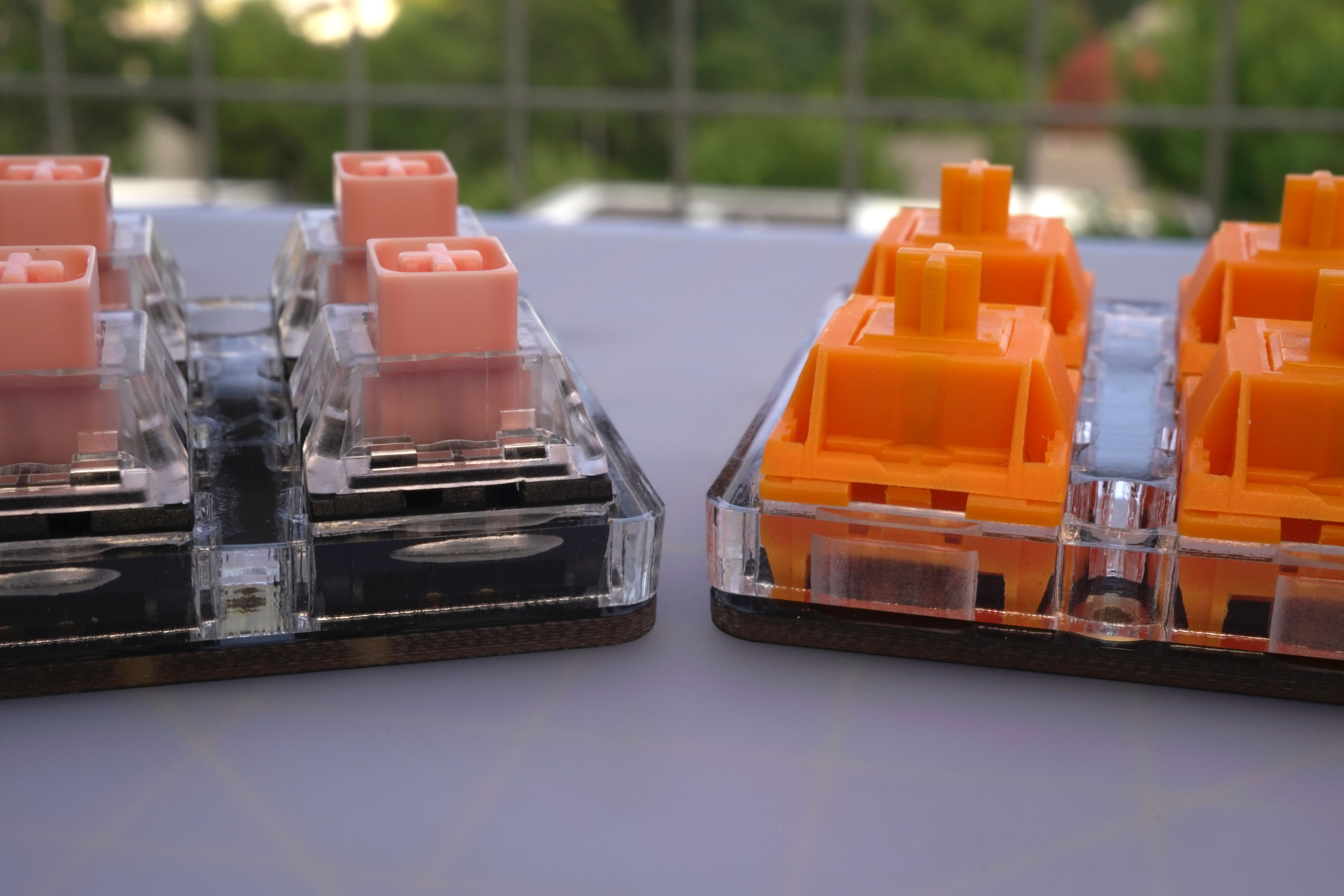
  • Switches sitting: Because the plate is thicker, the clips on the top and bottom of the switch will not sit securely in the plate. I.e. the switches will not click when you first install them.
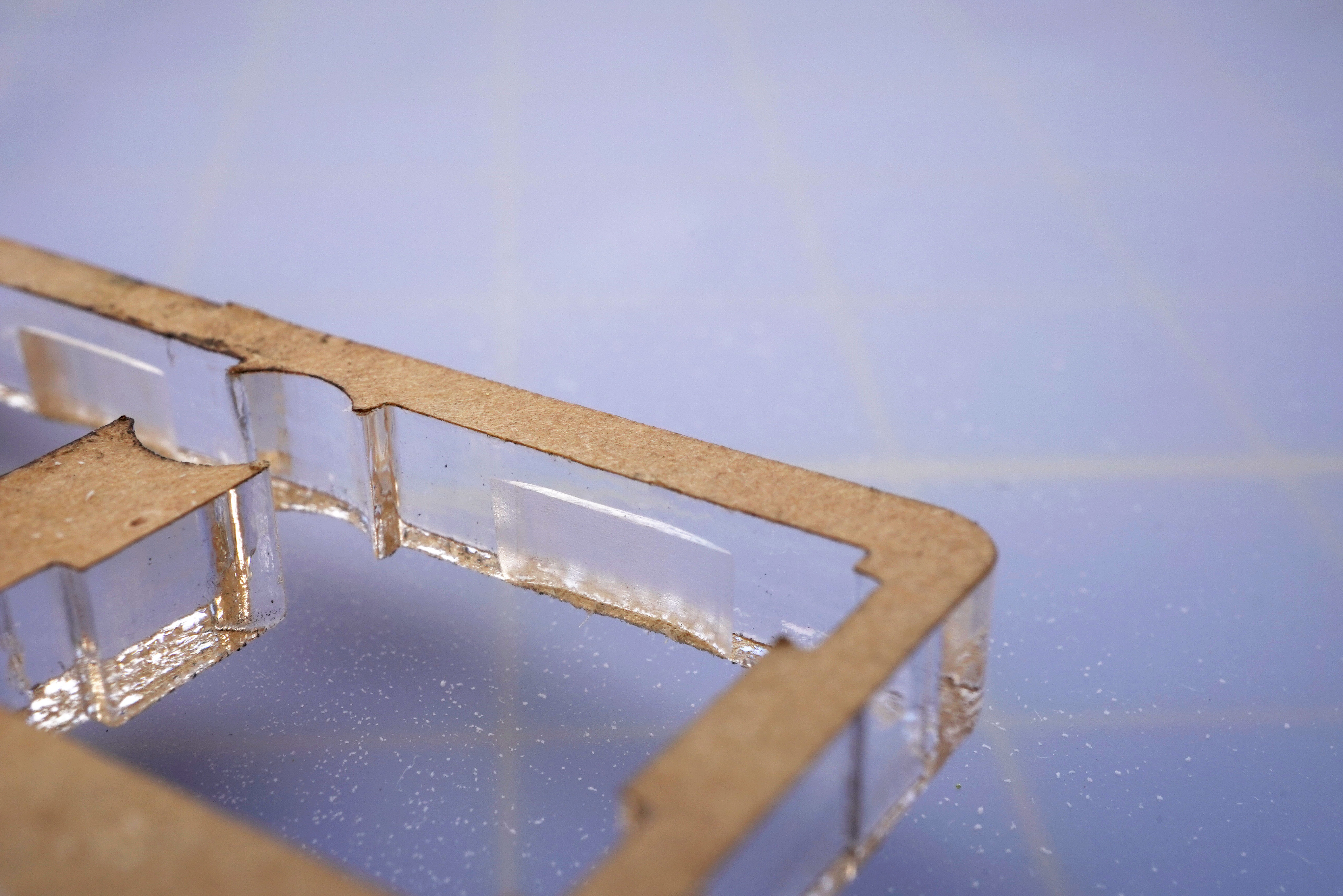
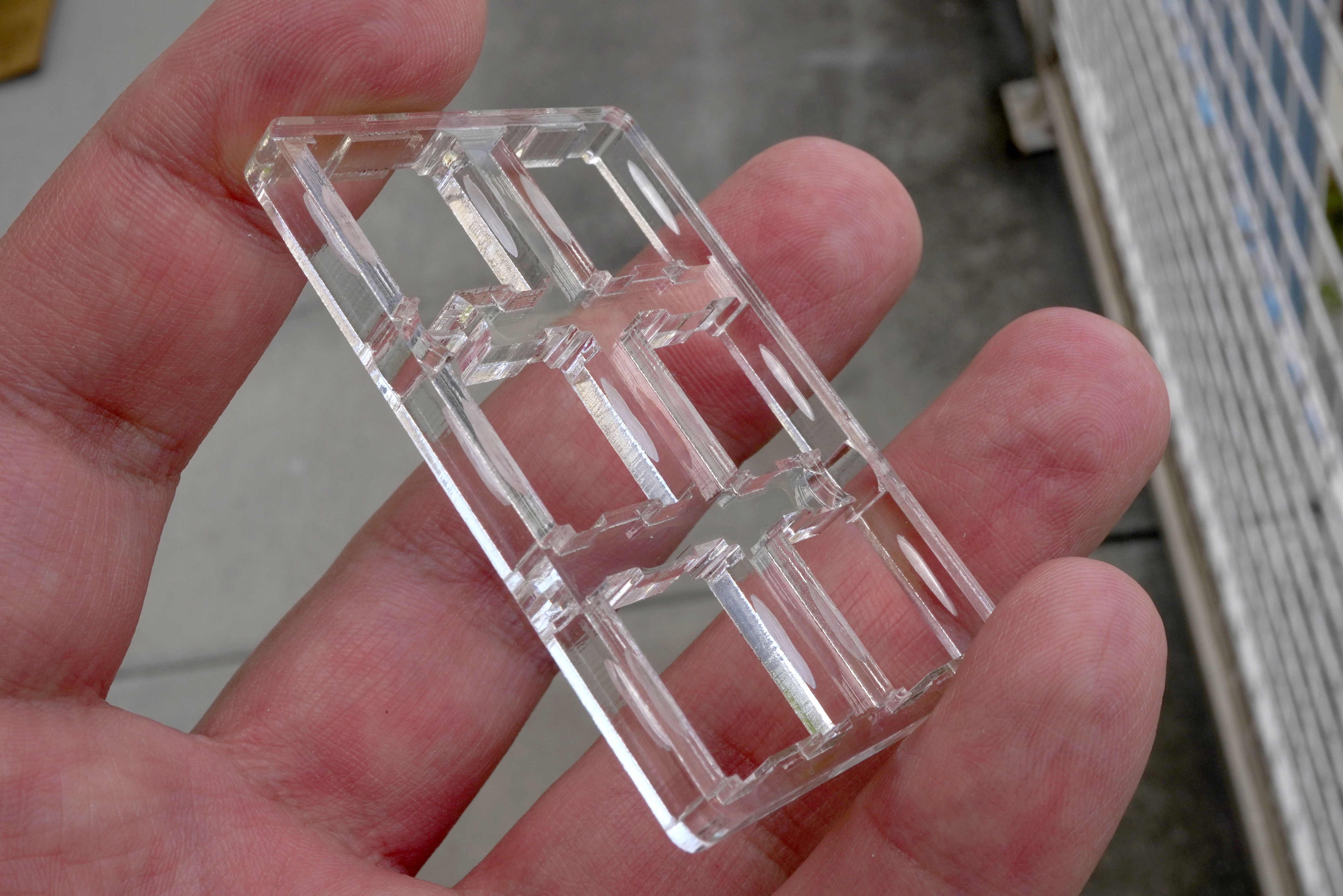
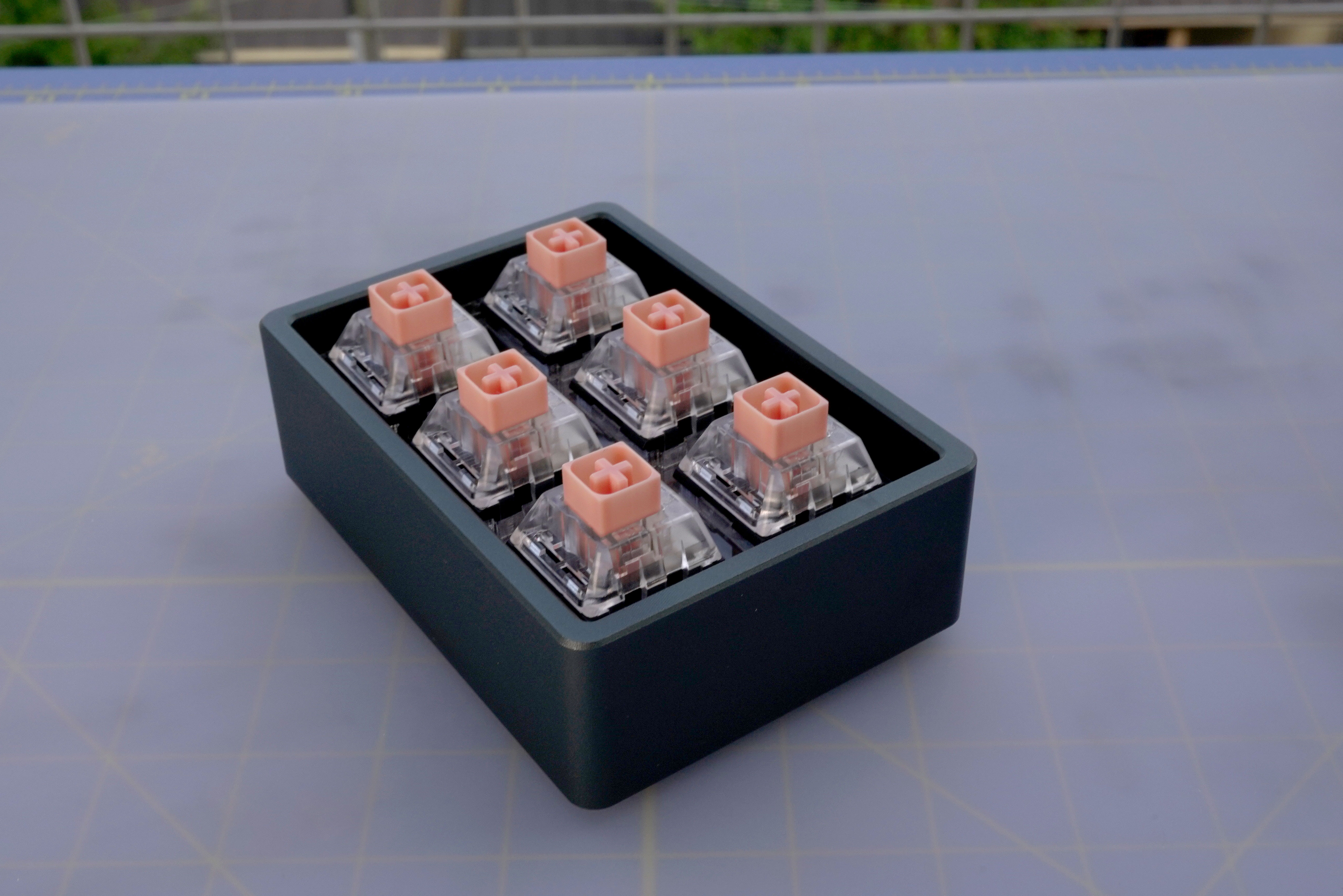
Here is the plate:

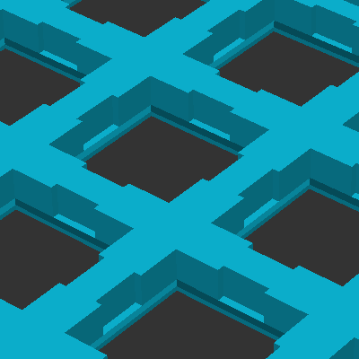
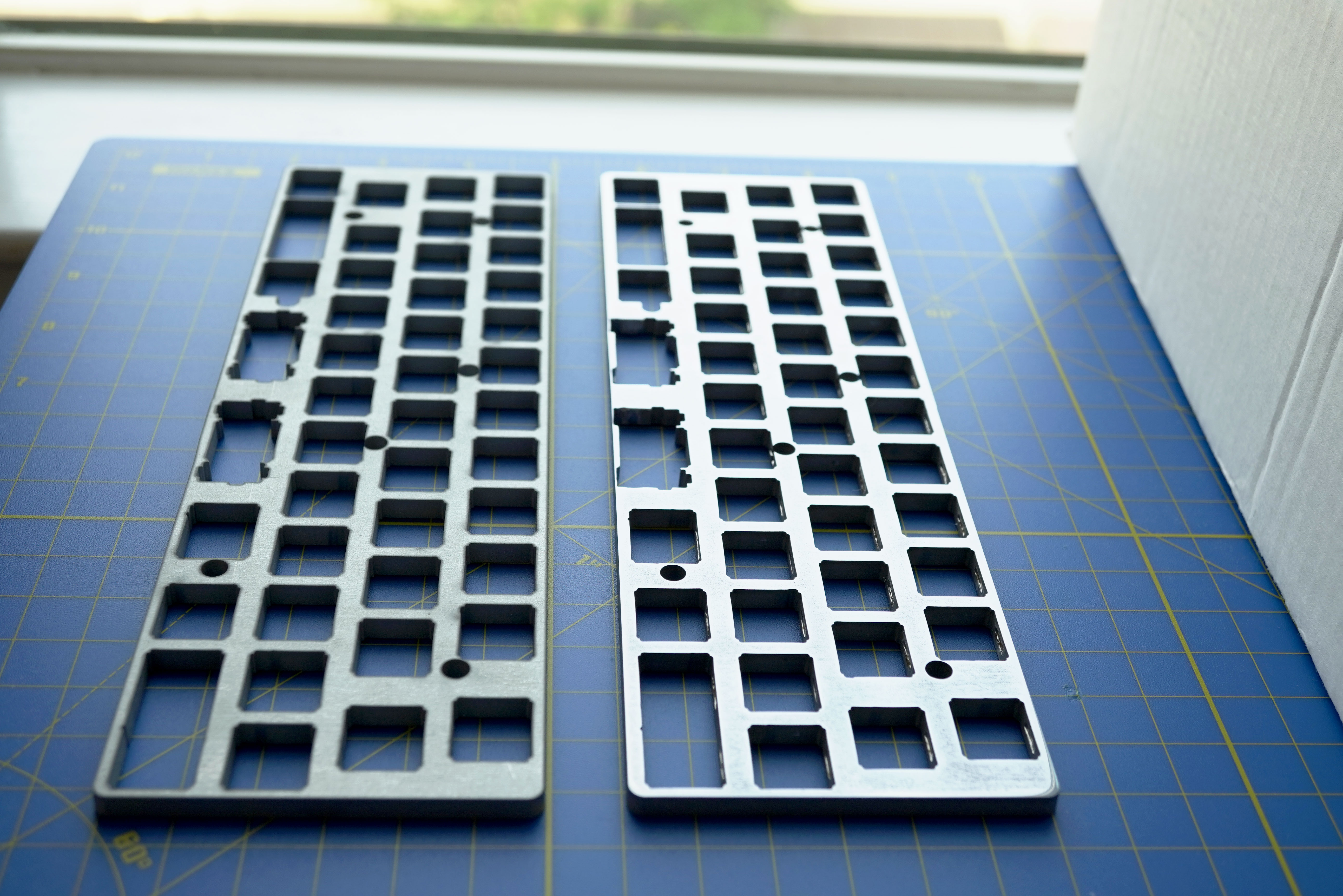
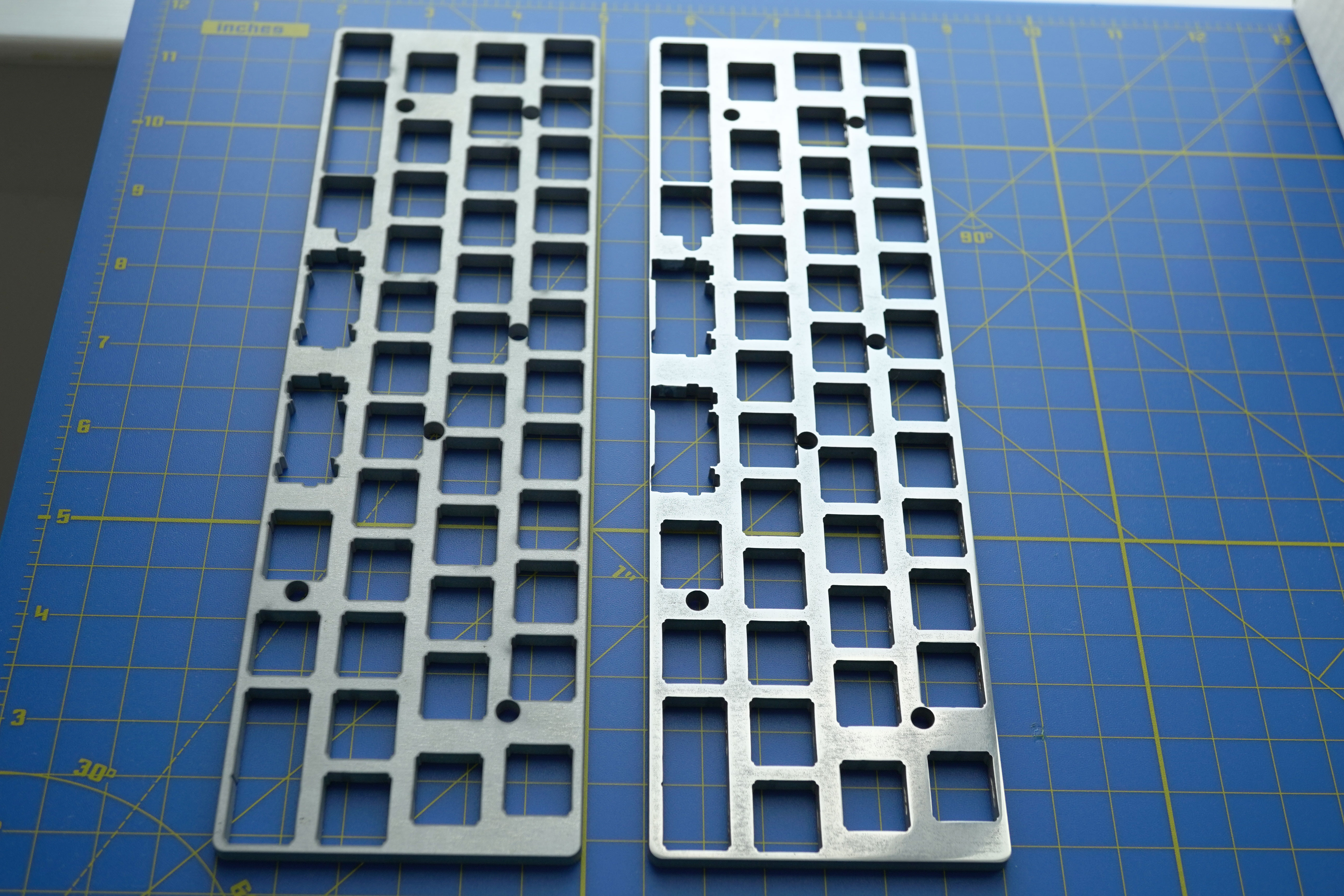
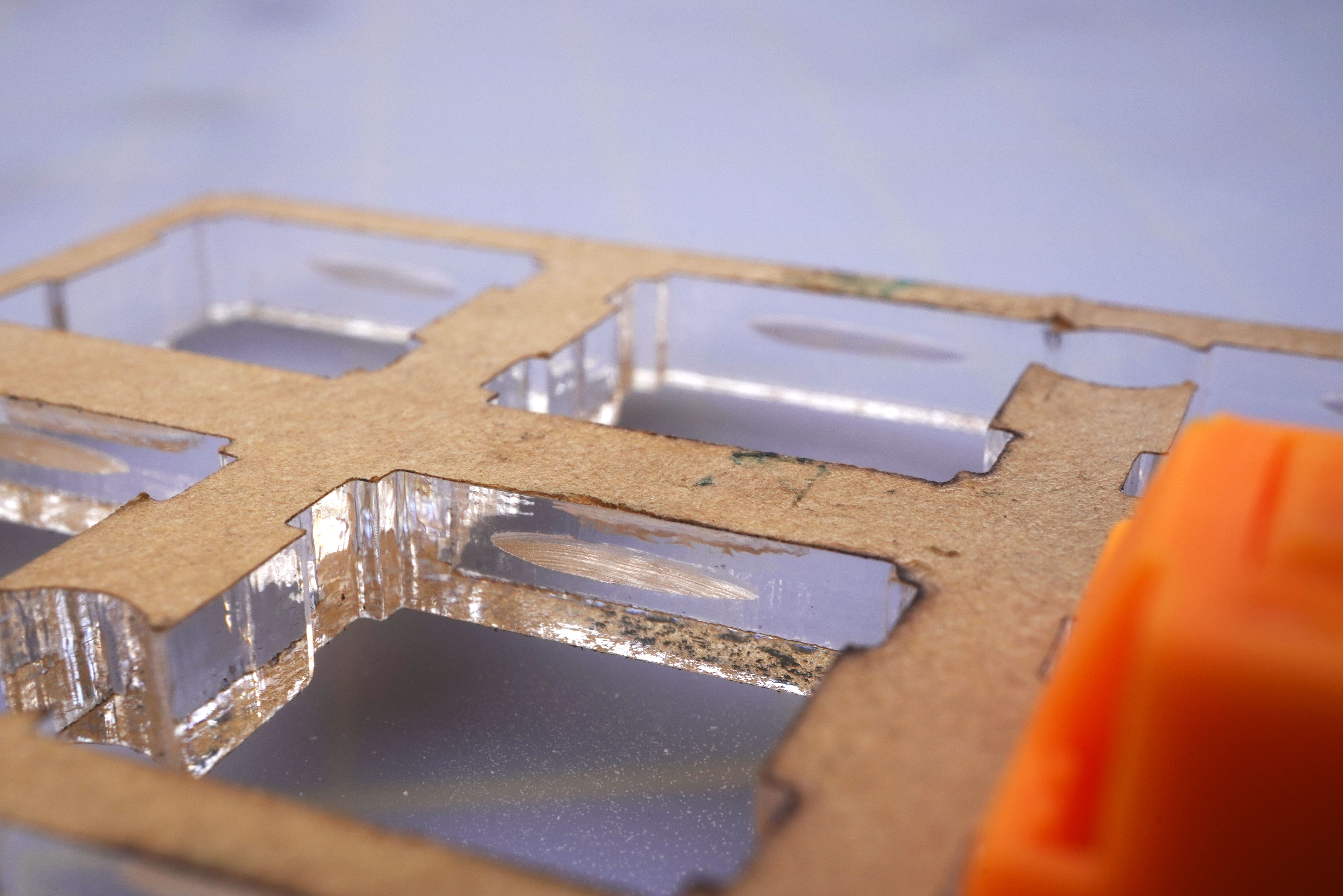
I decided to use plate mounted stabilizers, so I modified the plate to accept those. I had to remove some of the material at the bottom of the stab holes, here is a comparison of how much was removed:

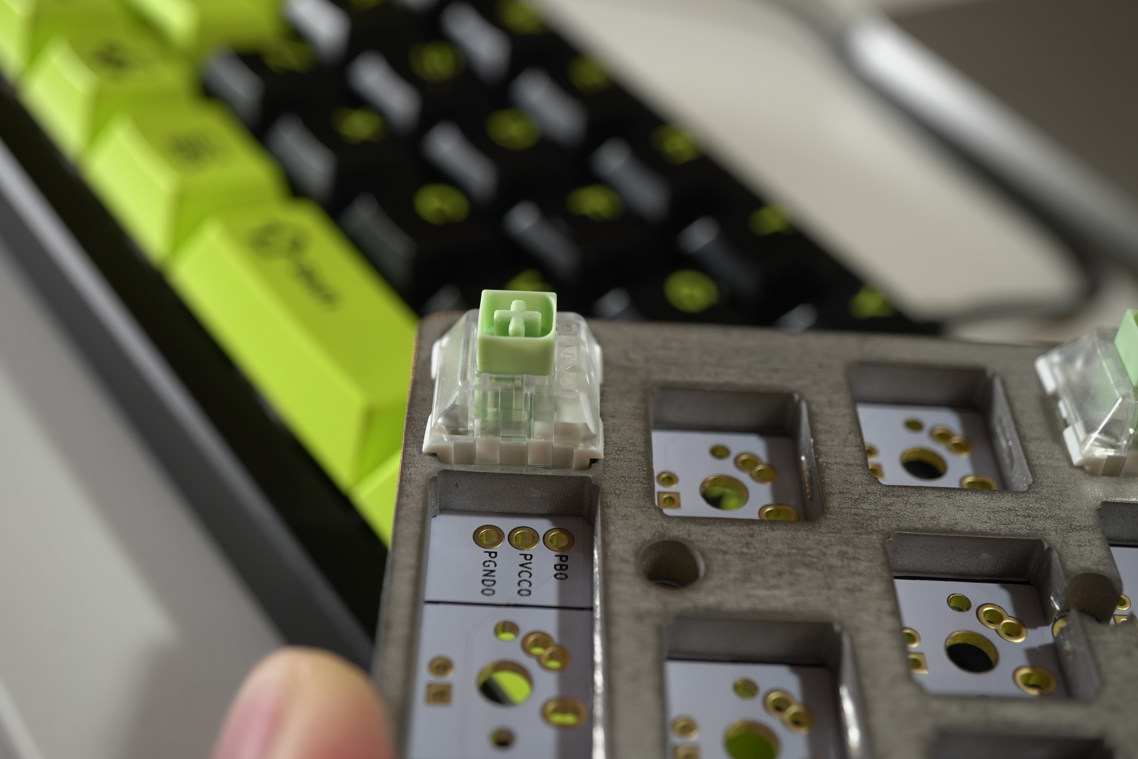
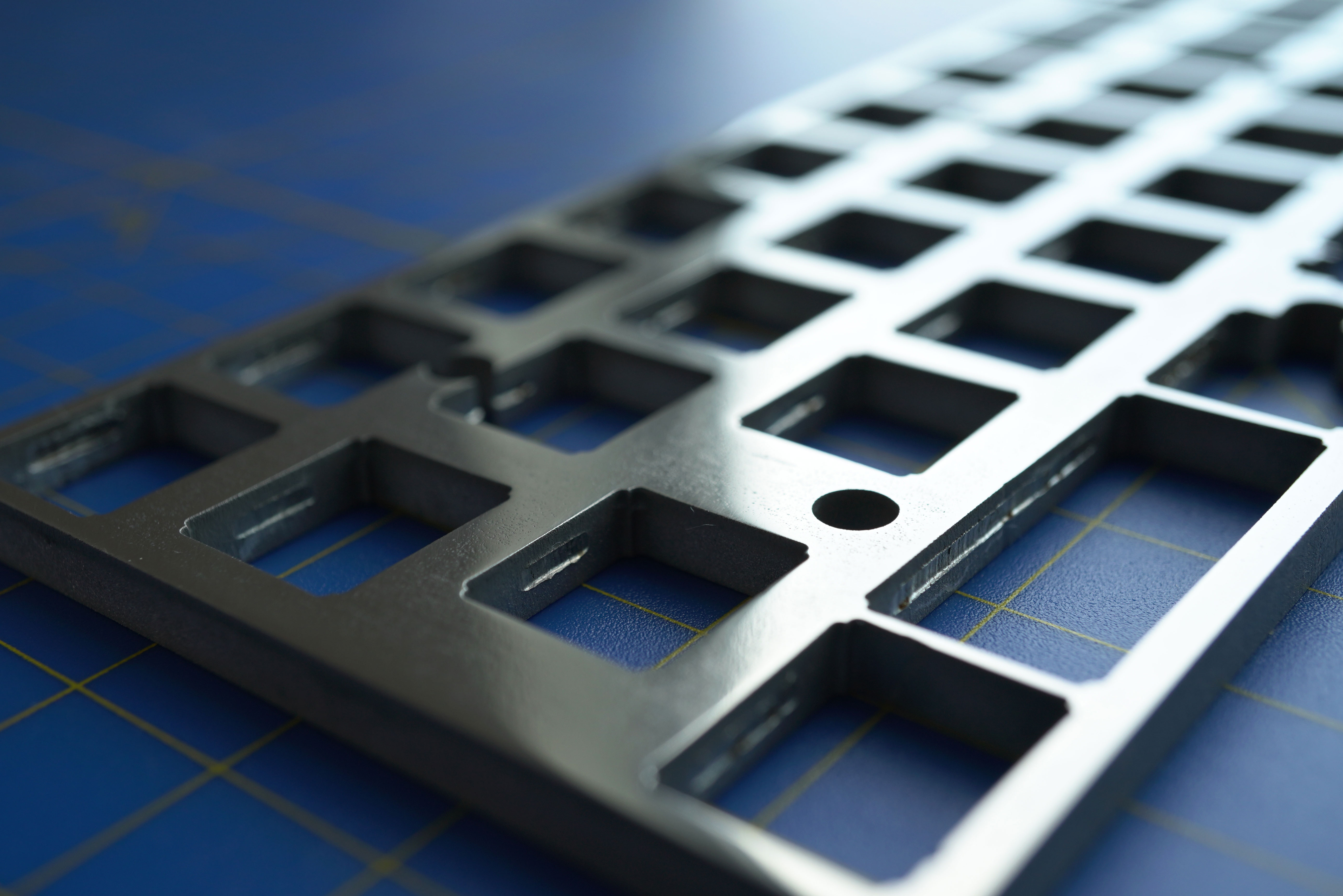
I also carved two notches on all the switch holes, top and bottom, so the switches clip and sit snug:

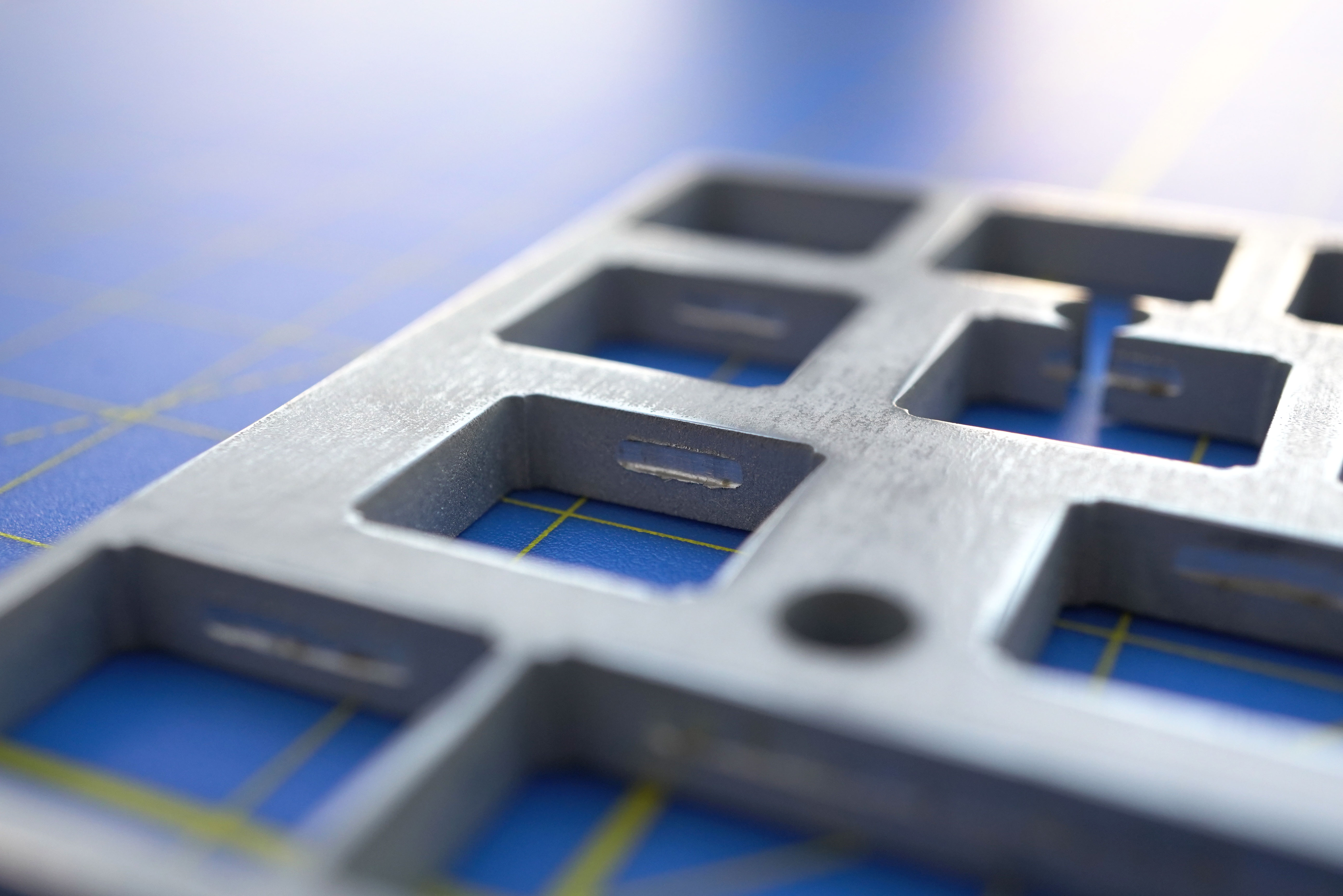
I am debating whether these notches are needed or not. The switches sit properly without the notches anyway. I guess if you are planning on using hotites to change your switches often, then the notches make a bit of sense. If you are not planning on changing switches, then the notches are an overkill.

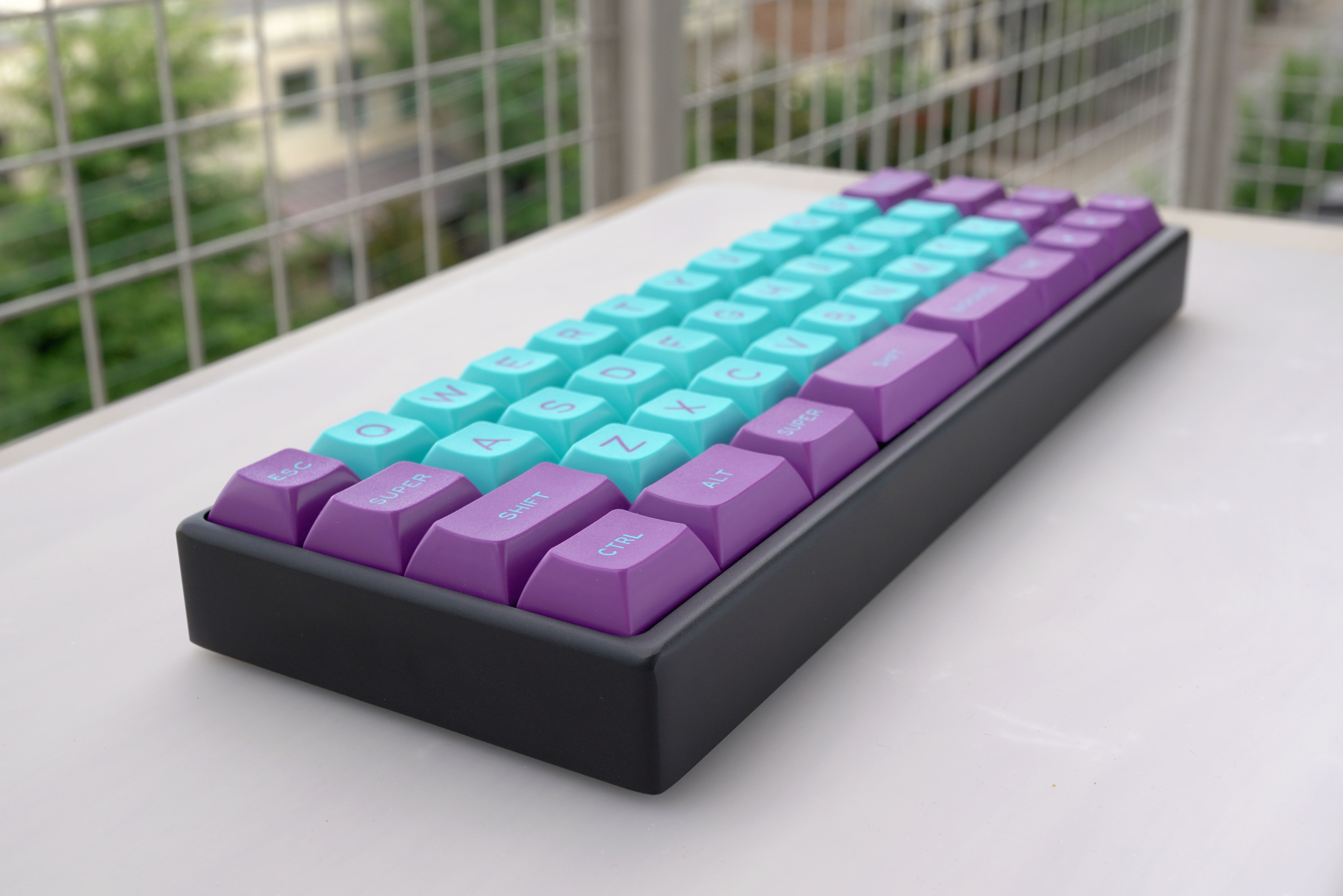
Now I need a case. I was only able to get the PCB.

Does anyone have a MiniVan case I can buy?
Yes, I saw the KUMO Kickstarter and yes I already joined. I was hoping to get this project done this year.

(This is my first post on Keebtalk!)

24 Likes

Email me, I’ve got some b stock cases evan@thevankeyboards.com

3 Likes

If you are already milling out the slots for the switches to clip in why not mill some breathing room for the traditional PCB mount stabs as well? This definitely looks like a really interesting project that I’ll be keeping my eye on, though. Great work so far!

1 Like

I love fat plates. I’m assuming this was laser cut. I don’t think there is any easy way to make provisions for switch snap-in and stabilizers on a purely laser cut plate. If it were machined it’s pretty simple but would likely be stupid expensive for a one-off.

1 Like

You’ve run into the main shortcoming of fat plates: without either machining in ledges (Lunar AEK) for switches to clip into or adding a foam layer (Modern M0110) or dots of hot glue on switches with 3mm acrylic plates, the plate will just slide right down the switches and sit on the PCB where you run the risk of abrasion or scratching (more so if any through-hole components were used (like diodes on the Alps64)).

A large chunk of plates currently are laser cut simply out of cost-cutting and/or time-saving measures. Machined plates (like the Monarch, Lunar, and Zephyr) add to production time and costs. I’ve seen a couple sources mention that cutting EVA foam is a nasty process requiring some industrial grade ventilation. And dots of hot glue on your nice acrylic plate ruin the whole æsthetic …

For laser cut acrylic, there’s the winkeyless.kr “cheat”: cut the top switch plate out of 1.5mm acrylic and then cut a 3mm support plate with larger holes that sits directly underneath the top layer to reduce the chance of cracking the top acrylic layer.

… which leads to an idea for a laminated plate – 2 or 3 layers of laser cut metal bonded together …

4 Likes

It’s recently become a trend in customs

2 Likes

@evangs, thanks!

@jetpacktuxedo: Just like @holtenc said, the plate was cut using water jet, so recessed areas have to be carved manually.

@cerement, I agree, that’s clearly the main problem with fat plates.
The reason why I don’t think it will be a problem with this plate is because this plate is so thick it will not fall, and also because the dimensions of the design and the tolerances of the execution make the switches fit quite snug. Also, raw stainless steel is pretty rough.

I just took a few pics of the plate with the PCB and switches, while I listen to this week’s Keebtown:

If you see below, the switch is all the way through the plate and through the PCB. The pins are protruding the same length they protrude if the plate was not there:

I’m pretty happy with the results so far.

Your idea of a laminated plate sounds pretty interesting, but a bit messy to build.
My Mechmini 1 uses this approach using acrylic plates.

You could do three layers:
1.5mm (top)
1mm (clips notches)
2mm (bottom)

6 Likes

that looks pretty good.

With a metal plate sitting directly on the PCB like that, does the plate itself bridge any of the contacts on the PCB (ie. in the backspace area if the PCB supports split backspace) ?

4 Likes

I was thinking that if they did, I would cut a transparent plastic wrap and put it between the PCB and the plate; that way the switch pins can punch through it. My only concern would be melting it when soldering.

Gladly, none of the contacts touch the plate. The plate design matches all the keys, and there is no option for a long spacebar.

This is quite nice.

I made a ~4.5mm 3D printed plate-case that worked pretty well, but it was difficult to print and have it look nice. I may revisit the design soon if I can get some fresh PEI for a smooth print surface.

I have a Minivan prototype built from the concept that has a faux wood finish.

Also, I have a 3D printed minimal case on my Minivan if you need a temporary or plastic Minivan case to tide you over until Kumo drops. It’s nothing fancy, but it does work - so PM me if you’d like it.

Below is a render of my ~4.5mm design focusing on the 1u keys.

35%20PM

6 Likes

@keyboardbelle:
That’s an interesting design. I see that your picture is for an ortholinear keyboard. Have you done any staggered plates? I’ve been looking into machining a thick carbon fiber plate too, but my CAD game is no good.

Plate update:
I managed to polish the top side using several sheets of sanding paper, going up 200 grit at a time:

It might not look very appealing at first, until you compare it against the initial state (left is original, right is polished):

Here is a close up:

I also managed to get a Minivan case, so I will be lubing the Kailh BOX Jade switches and possibly soldering tomorrow evening.
Should I paint the case…? I digress

5 Likes

Those are gorgeous :heart_eyes::heart_eyes::heart_eyes:

Update:

I lubed all the switches, inserted them in the plate, and lined up the PCB.

The PCB slid in quite smoothly, with minimal adjustment on the switches:

Because the plate is so rigid and flat, the pcb and the plate aligned flush all the way around:

And here is everything soldered, inside the case, and with a neat keycap set (DSA Skeletor):

I am truly surprised with how good the fitment was.
If I ignore the plate modification, this has been one of the smoothest keyboard builds I’ve ever done.

Key findings:

  • The DXF file needs some adjustment to account for the plate mounted stabilizers.
  • The top and bottom notches for each switch have to be carved independently unless your plate is machined with a design, such as the one mentioned by @keyboardbelle. I am still not 100% whether they are needed or not when you use a plate over 4.4mm thick, because at that thickness the plate will not fall onto the PCB. Also, if you are using a material that is as coarse as raw stainless steel, then the switches will not move around when installing. If you are planning on using a plate between thicker than 1.5mm (>1.5mm) and equal or less than 4mm (≤4mm), then I strongly recommend carving the notches on each switch. (Good tips from @cerement)
  • Shorting: most PCBs out there offer multiple positions for several keys in your layout, e.g. split spacebar, 2u left shift, 1u arrow cluster, ISO enter, etc, etc, etc, etc, etc. Because of the multiple options and pin holes in the PCB, you risk shorting your PBC when using a fat plate (>4.5mm) made from a conductive material.
    I managed to pull this off by using a plate design provided by the manufacturer of the PCB (@evangs via TheVanKeyboards site); the plate did not short any of the keys.

This is most likely the end of this keyboard, but it is certainly not the end of the fat plates journey.
There are a couple more ideas that I want to investigate. I will keep this topic updated with my findings.

I hope this discussion sets precedent for anyone that wants to incursion in the fat plate realm.

5 Likes

That looks clean - the fit is quite neat.

Here’s a close-up of a resin printed concept derived from my earlier plate screenshot:

The “clip” cutouts are 3mm deep, so the entire piece is 4.5mm thick and the cutout creates a 1.5mm section where the clips can snap on like a standard plate.

I had created this with 0.3mm tolerance on the switch cutouts for a standard 3D printer, but SLA seems more exact and I can possibly lower that tolerance down to 0.1mm for a tighter switch fit.

I’ll take some more photos when it’s closer to being assembled, I chipped the edge of the print, so I may use this print as a post-finishing practice piece.

6 Likes

I’m back with the fat plates, this time with custom acrylic.

The project leverages the Techkeys SixKeyBoard PCB and case. It is not a very difficult host, but I wanted to experiment with the material and a couple approaches for the switch notches.

The plates were laser cut on 4.5mm (0.177 inches) thick clear acrylic.

I think the plate is thick enough, but there is still a small gap between the PCB and the plate; I could have made it ~0.5mm thicker:

The transparency on the plate allows me to see how the switch tabs are pushed all the way in when there are no notches on the plate:

Because acrylic is so soft, and because I had two plates and PCBs, I tried to carve the notches using two different approaches.

The first one was using a straight bit in order to carve a notch all the way from the bottom of the plate up until 1.5mm from the top of the plate, very similar to the notches found in the Zephyr plate.

The second approach was to use a small circular cutting wheel that carves a pocket on the inner side of the switch whole. The notch is about 1mm tall, and it has to be very carefully measured from the top of the plate so it aligns properly with the switch tabs

Here is the plate with the notches before I solder the PCB

Here are both boards assembled and soldered

You can clearly appreciate the difference between both approaches

Both approaches work well, no concerns. The small pocket is much faster to carve and releases much less dust. I wonder if this is possible on other materials…

5 Likes

Do you mind sharing the 3d files for this plate/case?

1 Like

You are doing God’s work, Son.

This fat plate is something that I didn’t know I needed so much in my life.

2 Likes

So if I choose to go with a 4.3mm thick copper plate ( or steel) I don’t need notches for the switches? Will the DXF file from the swillkb plate builder be enough?

I enjoy how these fat plates look. I would like more of these.