Fresnel TKL F12 PCB, an optical PCB for my Frog

Hello keyboard enjoyers !

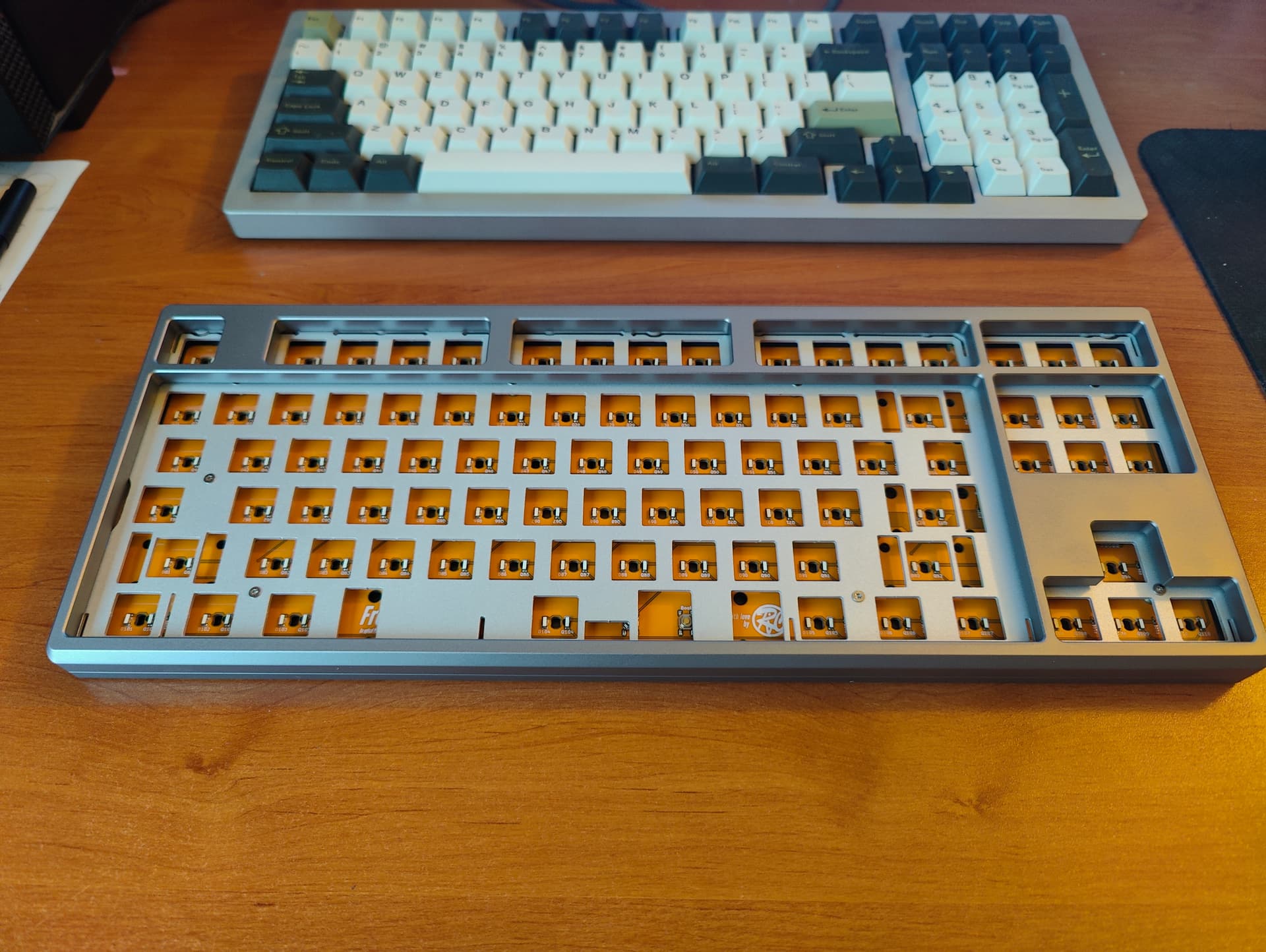
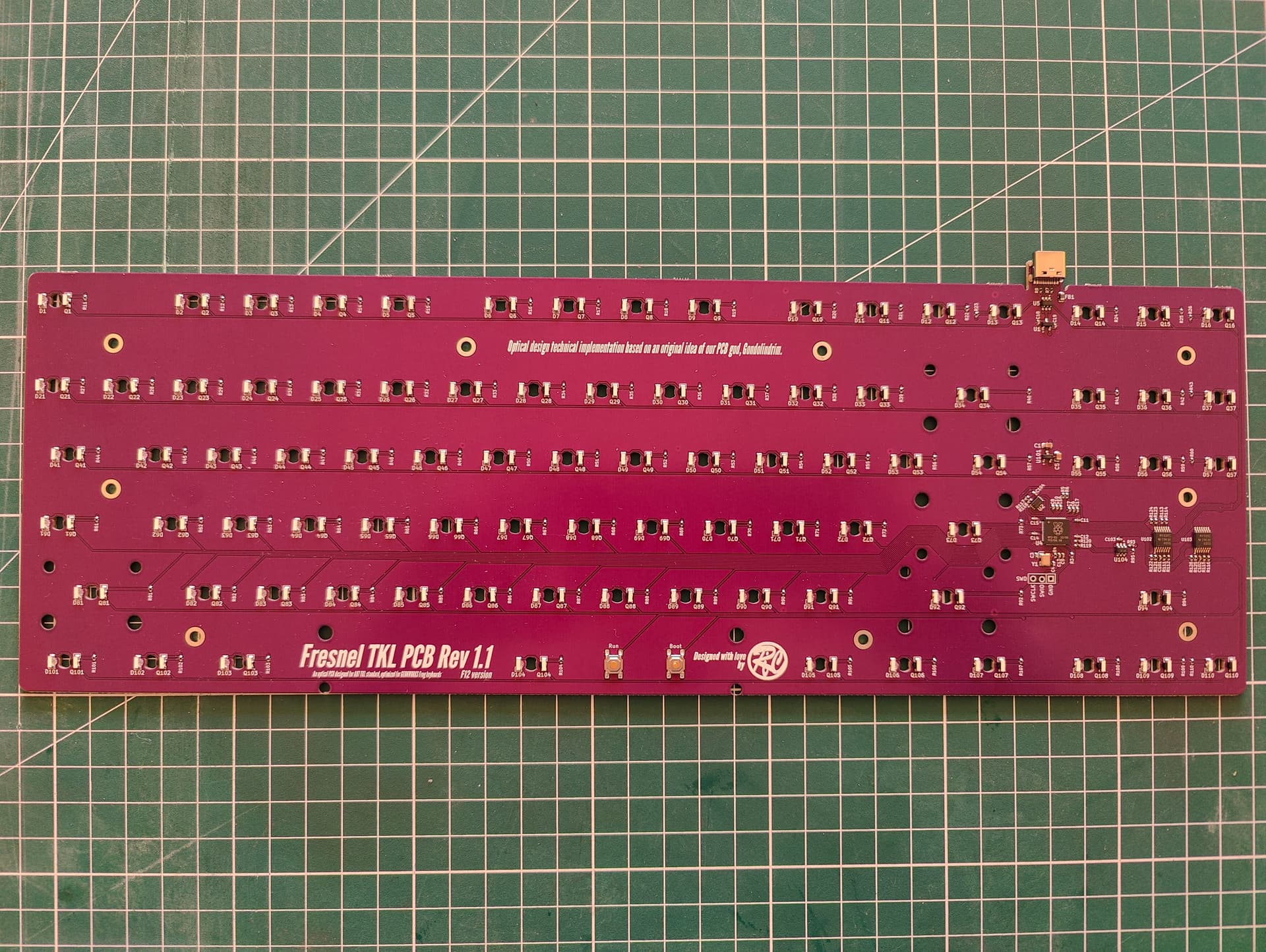
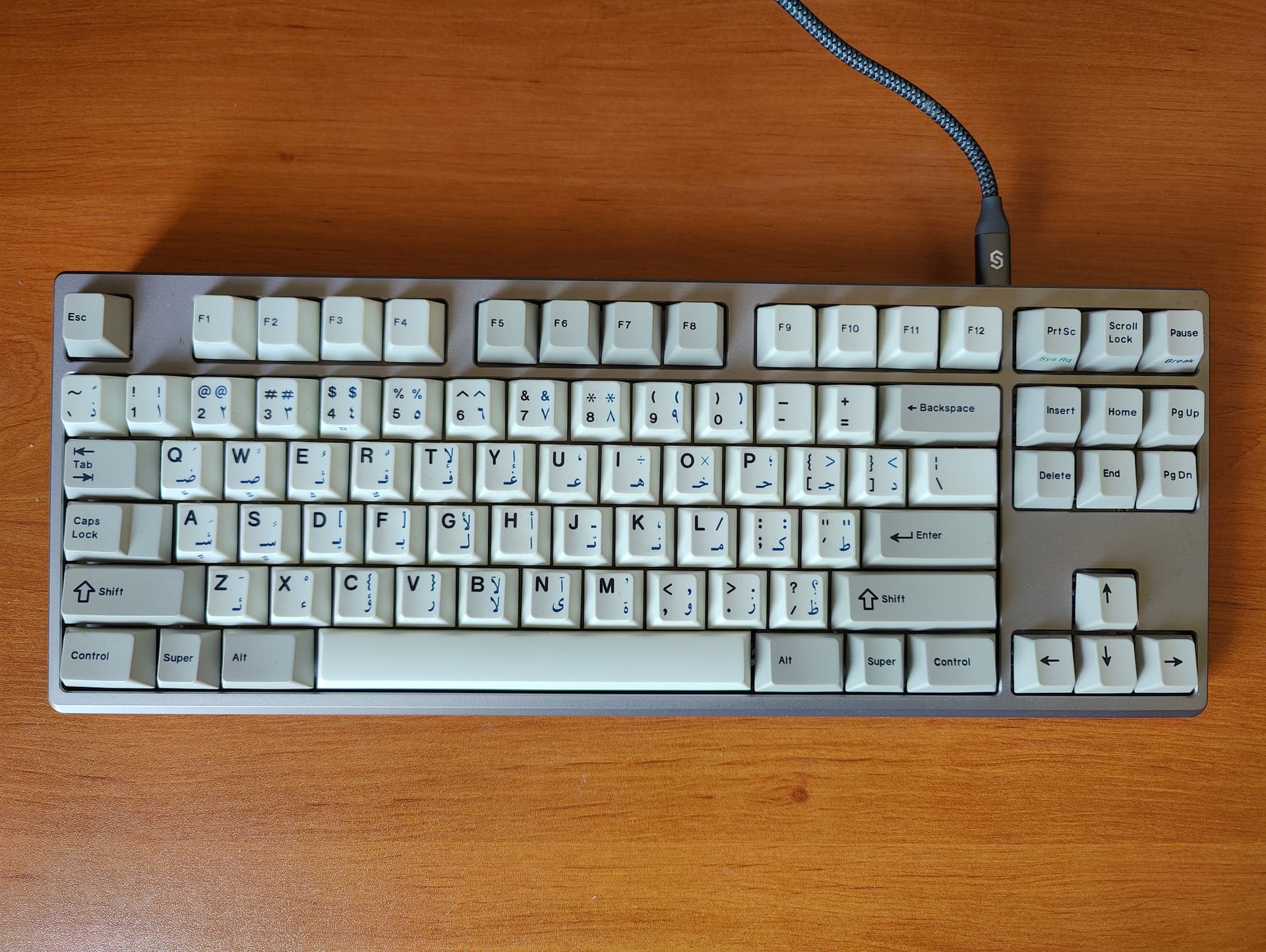
Here is my new personal project, a PCB using optical switches that is planned to be installed on my Frog keyboard.

You may have seen an old topic related to optical switches research in this forum:

A lot of research have been since done and this time I was far from alone doing this.
Our master Gondolindrim has shown great interest in developping PCBs for optical switches and as a result the fundamentals of optical technique used in the PCB presented here is his own invention.
So if it works don’t forget to thank him later, if not then I most probably have made a mistake on my side :smiley:

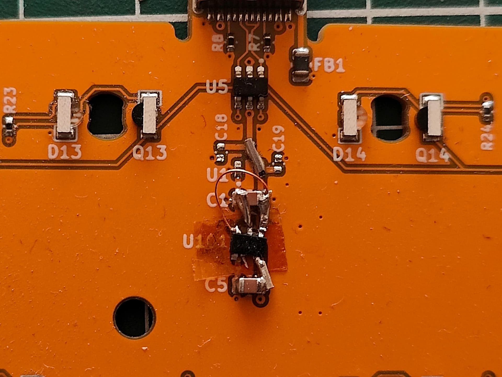
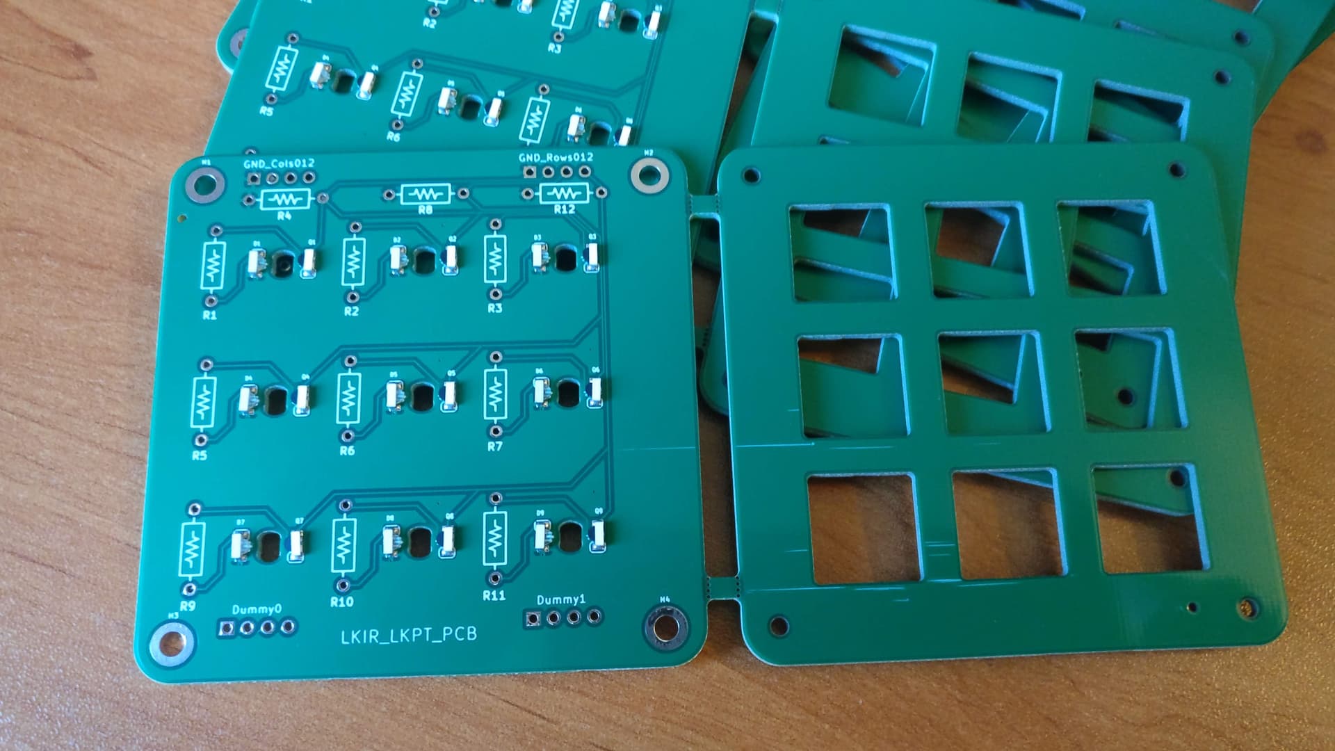
The first step has been to prototype something simple with all ideas in mind to battle proof it.
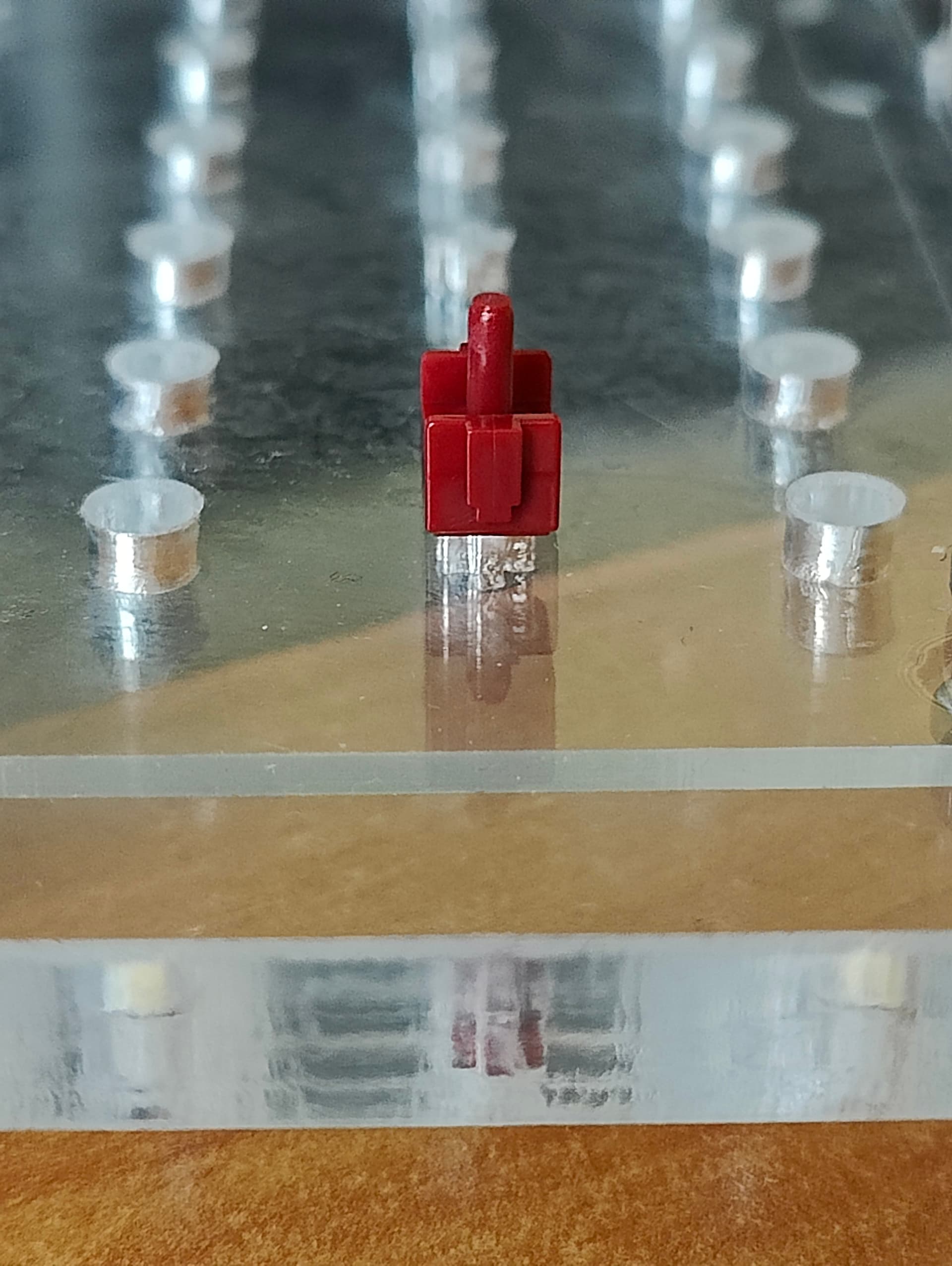
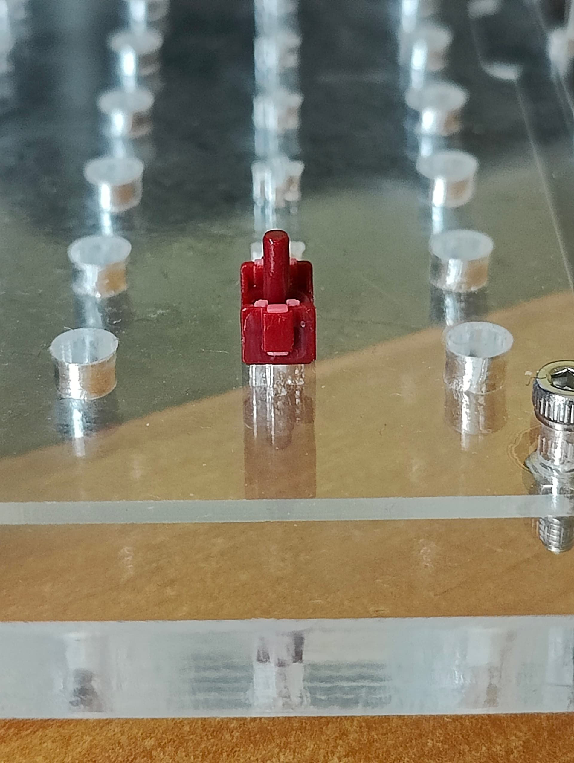
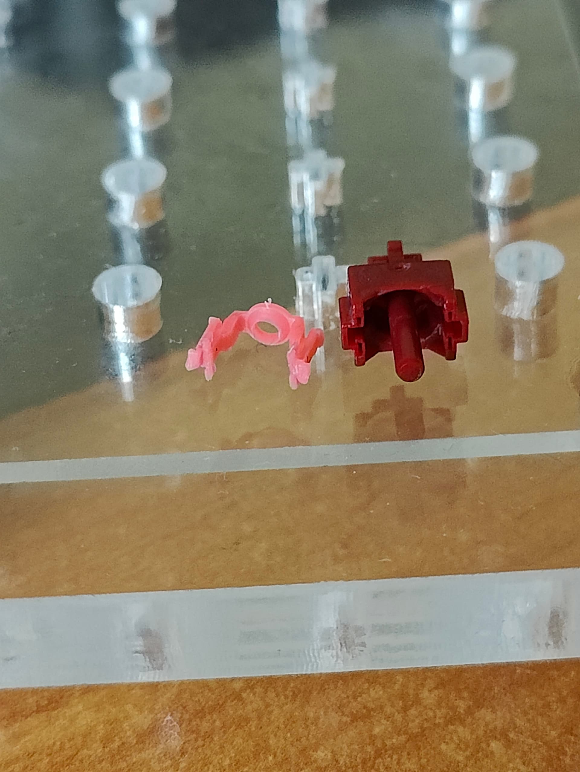
A simple macropad has been designed with a maximum of through hole components for ease of experimentation:

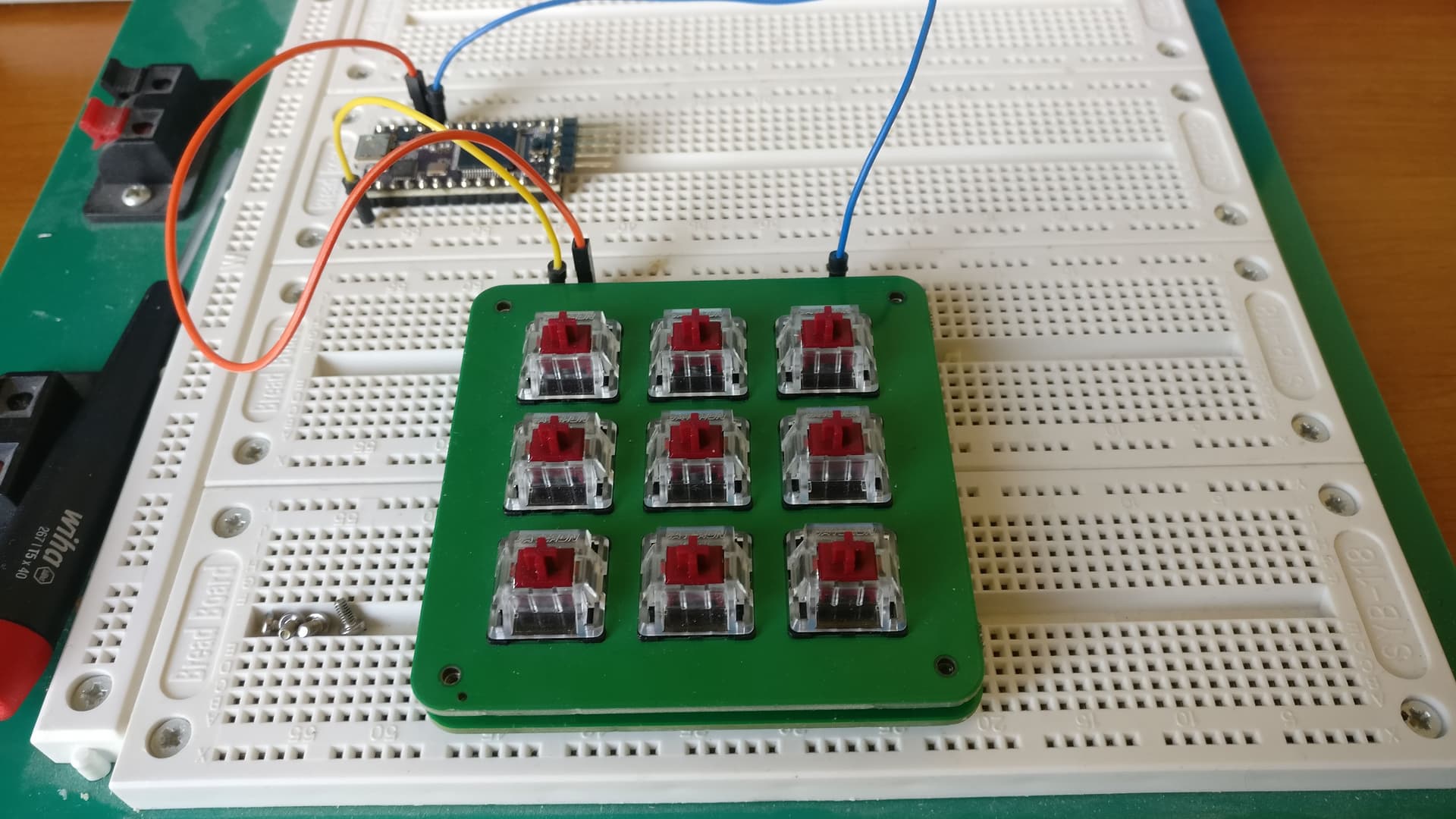
A few units have been sent to Gondo for him to do testing and write a QMK firmware. He did that live on Twitch and after a few hours he could have a working QMK firmware.

The prototype was far from perfect though, the latencies were quite terrible unless we used quite a lot of current.
As we wanted fast polling rate and not use too much current, something smart had to be done and Gondolindrim found the magic trick to do :stuck_out_tongue:

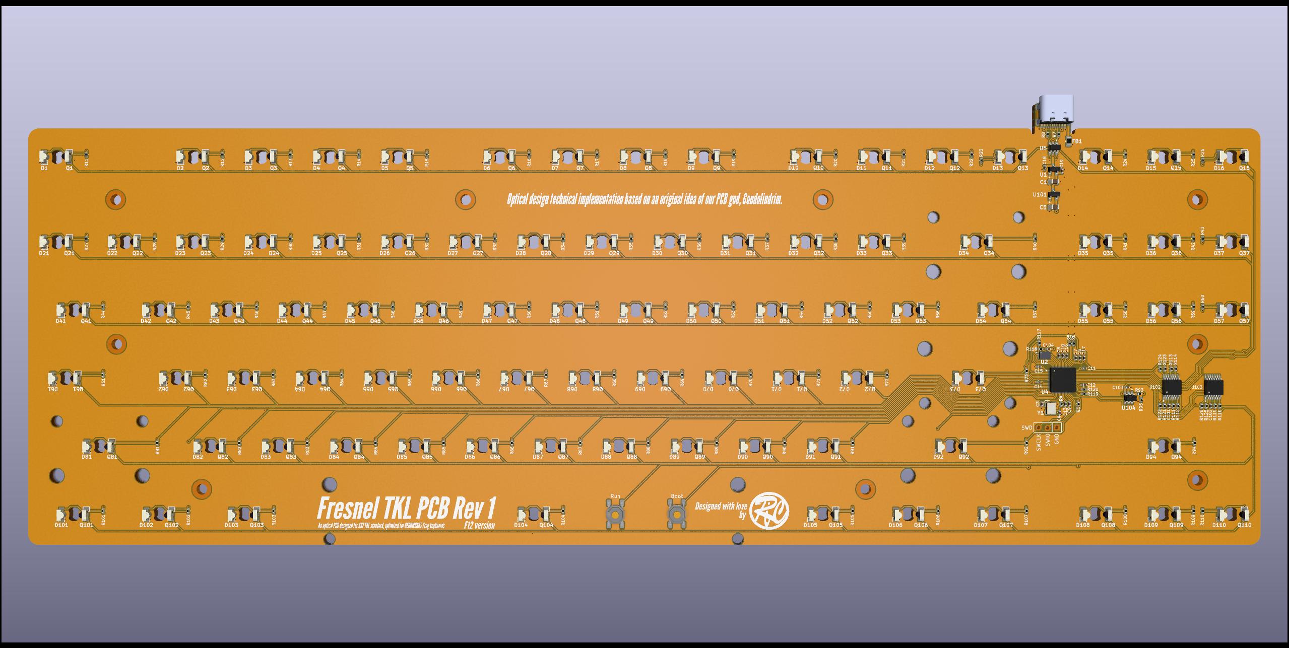
So what you’ll see below is using the magic trick found by him, with only minor tweaks on my side (that he is curious to see if they work as intended).

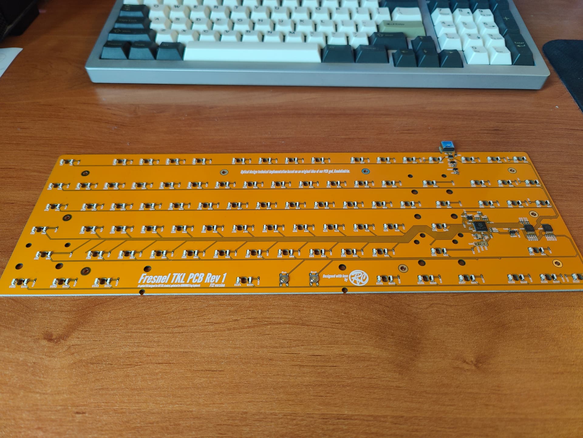
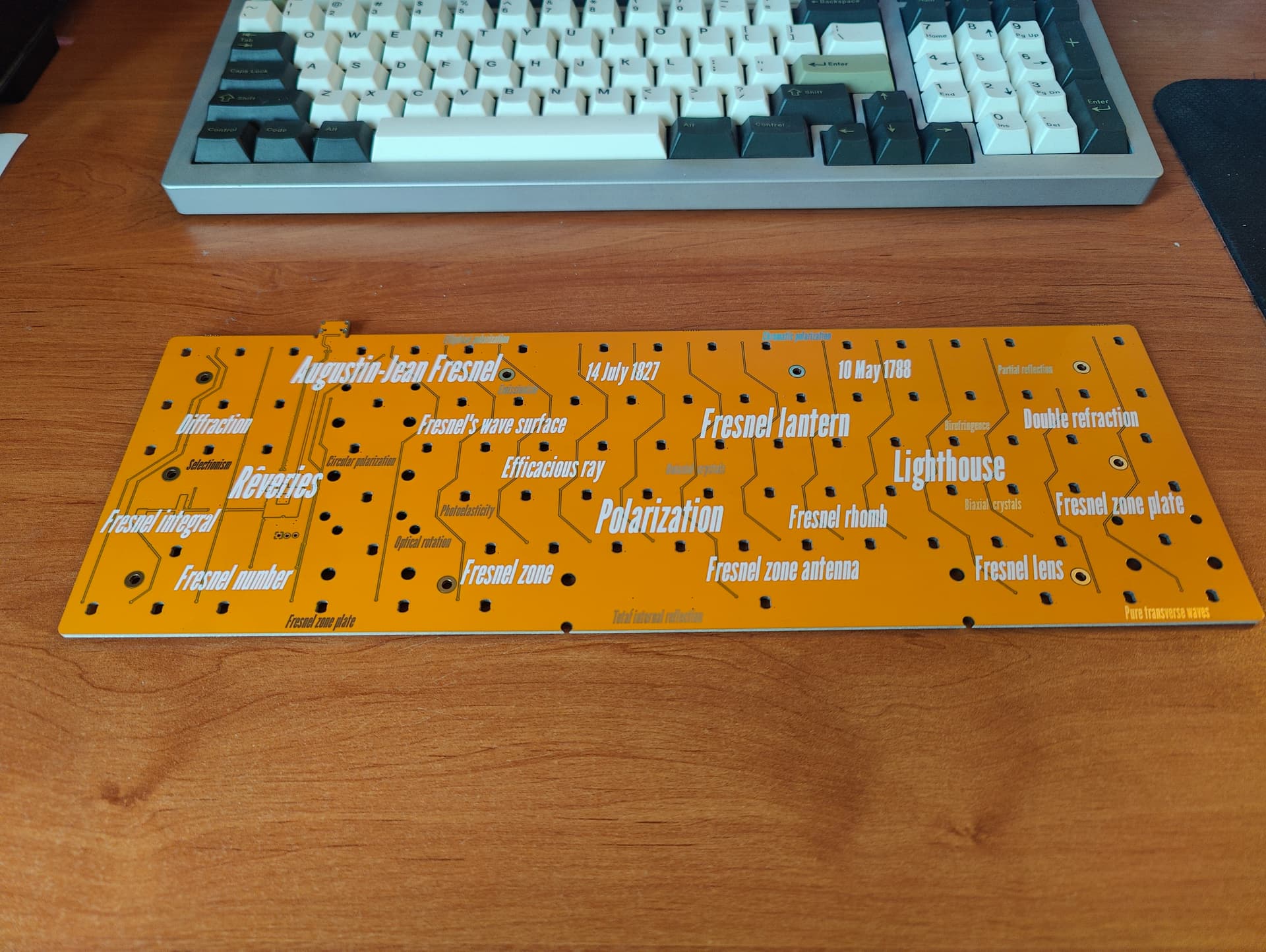
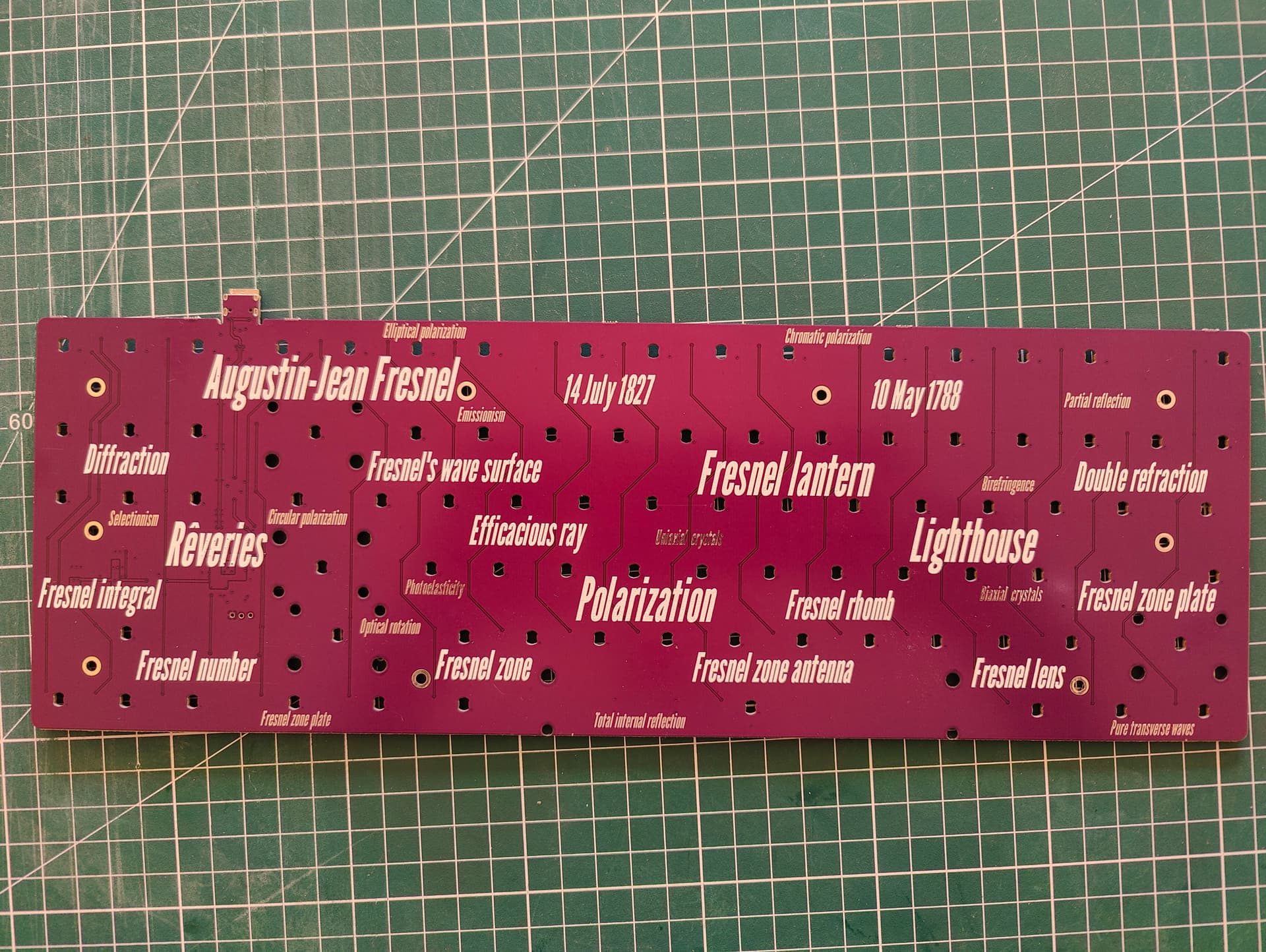
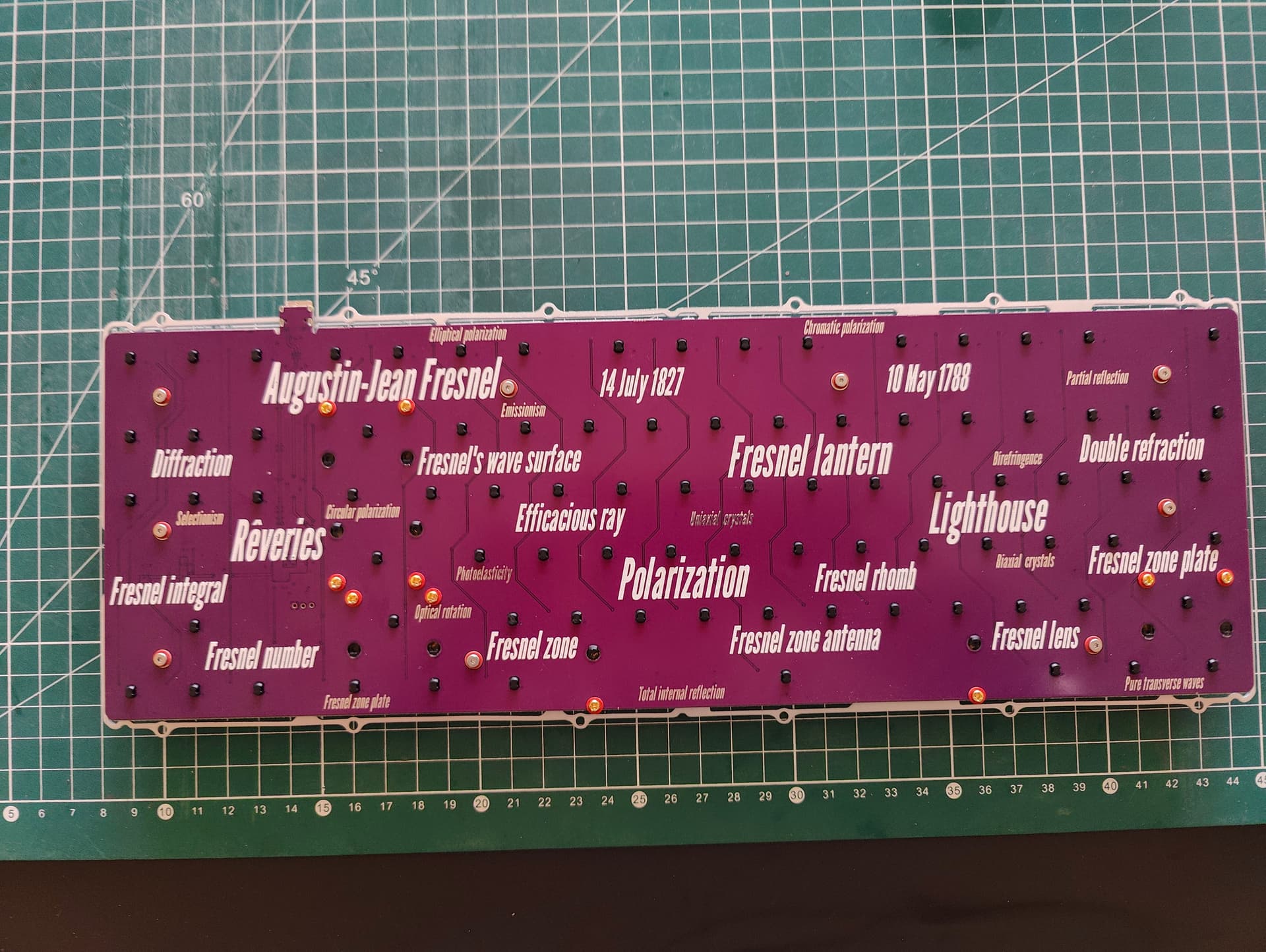
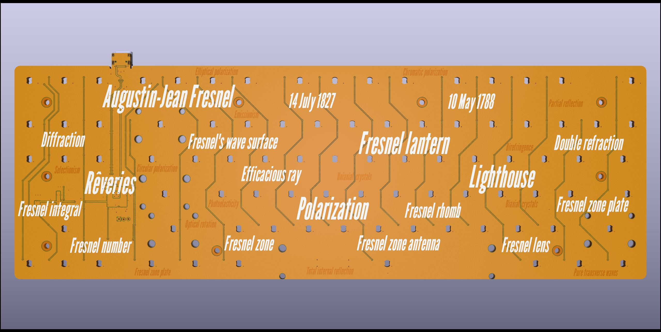
The name of the project comes from a French scientist that did many optical breakthroughs in the past (you may have heard of the Fresnel lenses).

The PCB will come in yellow, color of the sun :wink:

I do not plan to open source this design as the original idea is not mine.
Also Gondolindrim is looking at this technology seriously and I don’t want to interfere with his own projects.
But I am sure that if all this works he will be more than happy to share the technique with anyone and document it.

The PCBs are already ordered, and I am eagerly waiting for them :stuck_out_tongue:

See you !

5 Likes

Plates and PCBs received today !


I quicky checked the 2 assembled PCBs.

One is going to the bootloader just fine, a very good sign :slight_smile:

The other could manage to go to the bootloader only 2 times after numerous efforts.
Checked the temperature with my finger and both the MCU and voltage regulator were going hotter and hotter.
This looks like a short, I may have seen some bridges on the MCU pins and that could be the cause.
Nothing that a quick reflow with my iron can’t solve.
I hope that nothing took a beating befause of this short.
I have good hope though as the temperature rise was very controlled, this looks to be due to the e-fuse that I put in the design (in replacement of the standard polymer resetable fuses we commonly see in all PCB designs).
We’ll see in the future if adding this little innovation to the design has paid :wink:

Wanted to test the fit in my Frog case.
Found a small mistake in the plate design that forced me to use the dremel, otherwise everything looked fine :slight_smile:

2 Likes

Hello everyone !

Nearly one month has passed since the last post and no news.
Very often, things are not going the way you’d like and this time was no different.
In my case I discovered that the PCB would not want to reliably load firmware code from the flash.

And this has been a pain in the butt to figure out what was the problem: to remove any potential unknowns I desoldered and replaced all components that I never used before by models I know well, and this made a mess on the test PCB :smiley:

This is dirty but allowed me to confirm that the only culprit was the way the flash was laid out, quickly confirmed by a PCB design inspection that revealed no ground plane below the signal traces :frowning:
While not been able to correctly boot a QMK firmware, I could load and debug any program I wanted using SWD debugging. This allowed me to experiment with matrix scanning and confirm that Gondolindrim technique was indeed working like a charm :slight_smile:

So all is not lost for this Revision 1 PCB but if I wanted to have my Frog working with an optical PCB I knew I had to work on a Revision 1.1 very soon.
I recently received the Revision 1.1, time for a test !

I changed the color to purple this time in order for me to easily differentiate both revisions.
Apart from a better QSPI Flash routing and silkscreen color, there are very little differences between the two revisions.

… and I could finally manage to make a QMK VIA firmware work !!!

Time to assemble everything in my Frog now :slight_smile:


The specially designed plate (based on GEON files) was not very dimensionally accurate, some leaves were even looking a bit distorded (see image below). Not a huge deal but I had to rely on manual filing so that the plate could fit in the case without scratching the top part. I attribute that to the laser cutting process that put a lot of heat on such thin elements and deforming them.
I better understand now why GEON is CNCing all its metal plates :smiley:

The switches used are old KS-15 Gateron opticals, they have been lubed (304), filmed, and spring swapped (TX 16mm 55g).
The switches fit very tight on the plate, this is because they not only have notches vertically, but also smaller ones horizontally. No way to remove then accidentally by just trying to replace the keycaps.

Apart from that this is exactly the same process as for a standard installation.

Time to select classic beige keycaps to fit the grey Frog :wink:

Everything works super nice, in fact I am writing this using my newly built Frog with Fresnel PCB inside :stuck_out_tongue:

Next steps:

While it works nice it is far from perfect:

  • The current revision lacks standoffs to fully seat all witches to the PCB (I had to bend the plate a little bit to have a good switch to PCB contact).
  • The PCB has not cutouts to be able to use it on more keyboards cases and most importantly use O-ring mounting. This is something that Gondolindrim plan to address on the Revision 2 of the PCB.
  • I took little consideration to manufacturing cost but Gondolindrim is looking into it, as a result components will most probably change but the same core technique will be used and thus performance will stay the same.

See you !

6 Likes

Love it. With the plate… do you think you could make an FR4 version, or would it have too much flex? Do you have any photos that show how the plate is attached to the PCB? I see the screws but I assume there are standoffs between the two?

I would still love to try an optical board. I finally got my hands on a HE board, and I’m not the biggest fan of the switches out there. Wondering what the optical switches feel like in comparison.

1 Like

Arg, sorry I have no pictures of the inner assembly :frowning:
Yes they are Wurth metal standoffs, those are designed to be able to be soldered to the PCB, but you can also screw them on both sides like I did.

As for FR4 material, maybe but in this case I have the screws sunken to the plate and no PCB manufacturer provides an easy way to do this.
But this is just the start of the process to make something final.

As for the switch feel, the opticals are skating smooth and a bit on the clacky side (the top is PC, not nylon), I like that.

Heard bad things about HE switches, but GEON Raptor ones look to have good reviews.

1 Like

How are you liking optical switches?

1 Like

For the moment the sound is very inconsistent as I did not put enough standoffs to fix plate and PCB.

But for the switches that sit correctly, they are very clacky wich is quite pleasant.
They are all very smooth also, beeing contactless, even smoother than my old lubed Gat Inks that I have on another board.

This is a new kind of switch to play with, with I think a lot of opportunities to customize to make them even better.
And if enough succes some vendors may want to manufacture their own in the future, one example has been GEON with its Raptor switch (a better Gateron Hall Effect Switch with newer materials and a custom spring).

1 Like

I was not pleased by the inconstistant sound the switches were doing (randomly on a few keys) so I took the time to investigate.

I removed the silent/mushy keys, disassembled them and checked them.

A normal Gateron red optical stem is like that:

But I found that in the problematic switches:


No wonder why they felt mushy and silent, they are indeed a silent version of the Gateron optical red switch :smiley:
A few of those switches have mistakenly put in my bag of my unsilenced switches :stuck_out_tongue:

Not a big problem, just a matter of replacing those switches by the correct unsilenced ones and voilà !

The plate design still lack standoffs but at least now the board sound much more uniform across all keys !

2 Likes

That’ll do it :rofl:

Funny thing, I did not noticed when I lubed them.
Haha!

will this project ever be open sourced, amazing work and documentation here congrats on this.

1 Like

As it is a technique derived from Gondonlidrim solution, I will not open source it myself.
But it is planned that Gondo will do another revision, better, and also open source it.

1 Like