Hello keeb lovers!
I have been interested by optical switches for a long time.
Different technologies from what we are currently using (MX clones switches) are always good, this is the case for eletrocapacitive switches and this is also true for optical switches as well.
And optical switches are supposedly very smooth out of the box: no leaves contacts means less friction.
I started gathering various infos about the technology, components needed and their market availability/price, general documentation about those components and the theorical background behind optical switch technology.
During my research I found usefull information on various forums that I’d like to share here.
-
KeebTalk
Optical Switch PCB resources
No much technical infos but a lot of links including the one below. -
Geekhack
[IC] Optical Future: Custom Screws are in - still alive
This is Swishy IC about custom optical switches (gat inks like opticals) and optical PCB R&D.
Various information, including a link to a discord server named Optical Future. -
Optical Future Discord server
Optical Future
This is Swishy Discord server about optical switches R&D.
You can find here a lot of usefull ressources to get started:
- References to various IR led emitters and phototransistors components (already had them).
- Gateron optical switches datasheet and components PCB layout (a big thank you to Optical Future for providing those).
Gateron and Kailh optical switches are widely available at Aliexpress and other Chinese websites, and are not very expensive.
Both look to be frankenswitchable to a certain degree.
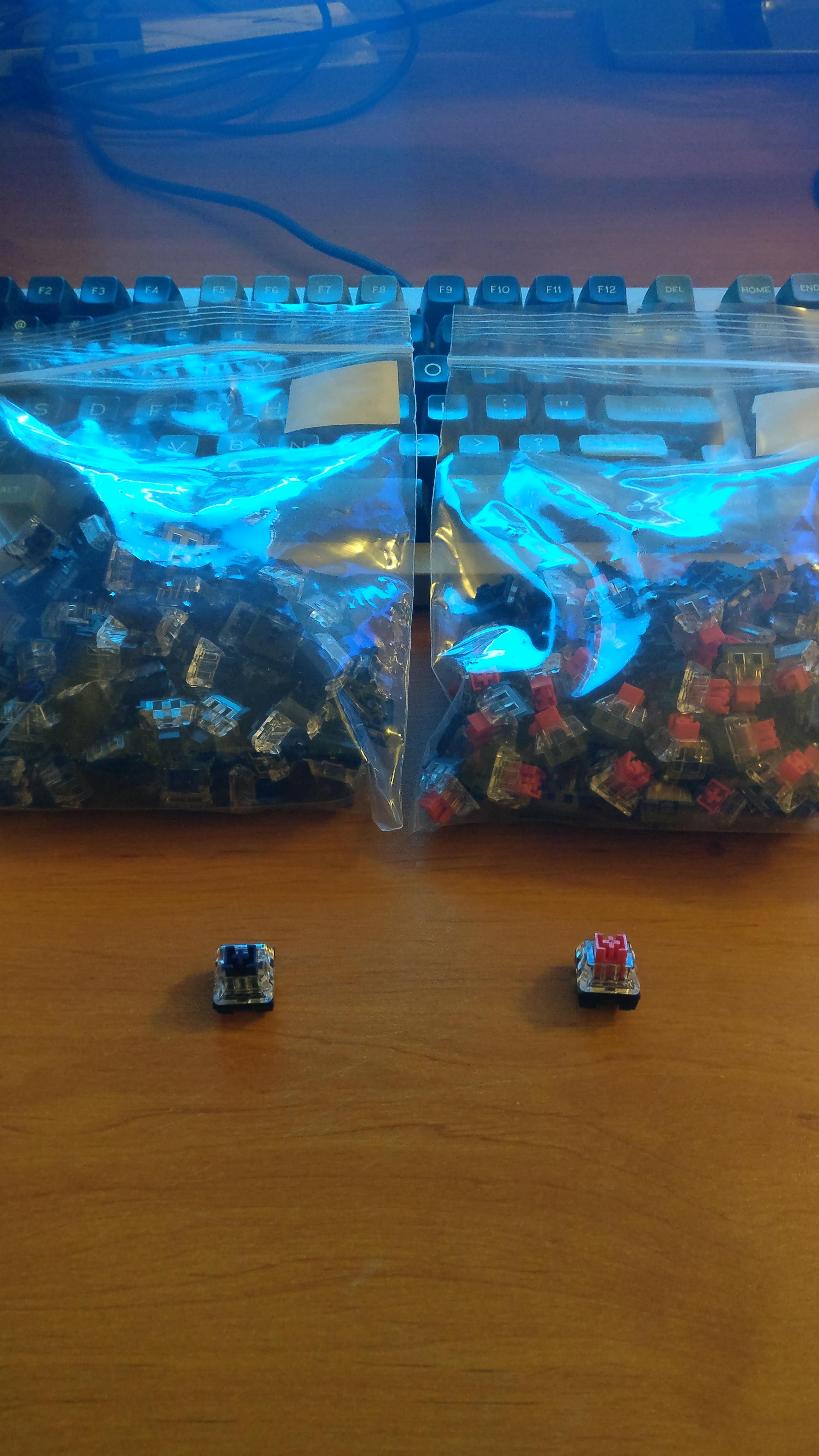
Gateron optical:
The stems, top case and springs look to be interchangeable with standard MX clone parts.
Keep in mind that the stem pole length drives the actuation height of the switch (the longer the pole, the sooner the actuation) so a long pole stem may make the switch actuate sooner.
Kailh optical:
Top case, springs (no a lot of replacement offerings for Kailh), and click bar look to be interchangeable with Kailh BOX parts.
General working principle:
For each switch mecanism you have three major components:
- The optical switch (Gateron or Kailh).
- An IR led emitter.
- A phototransistor receiver.
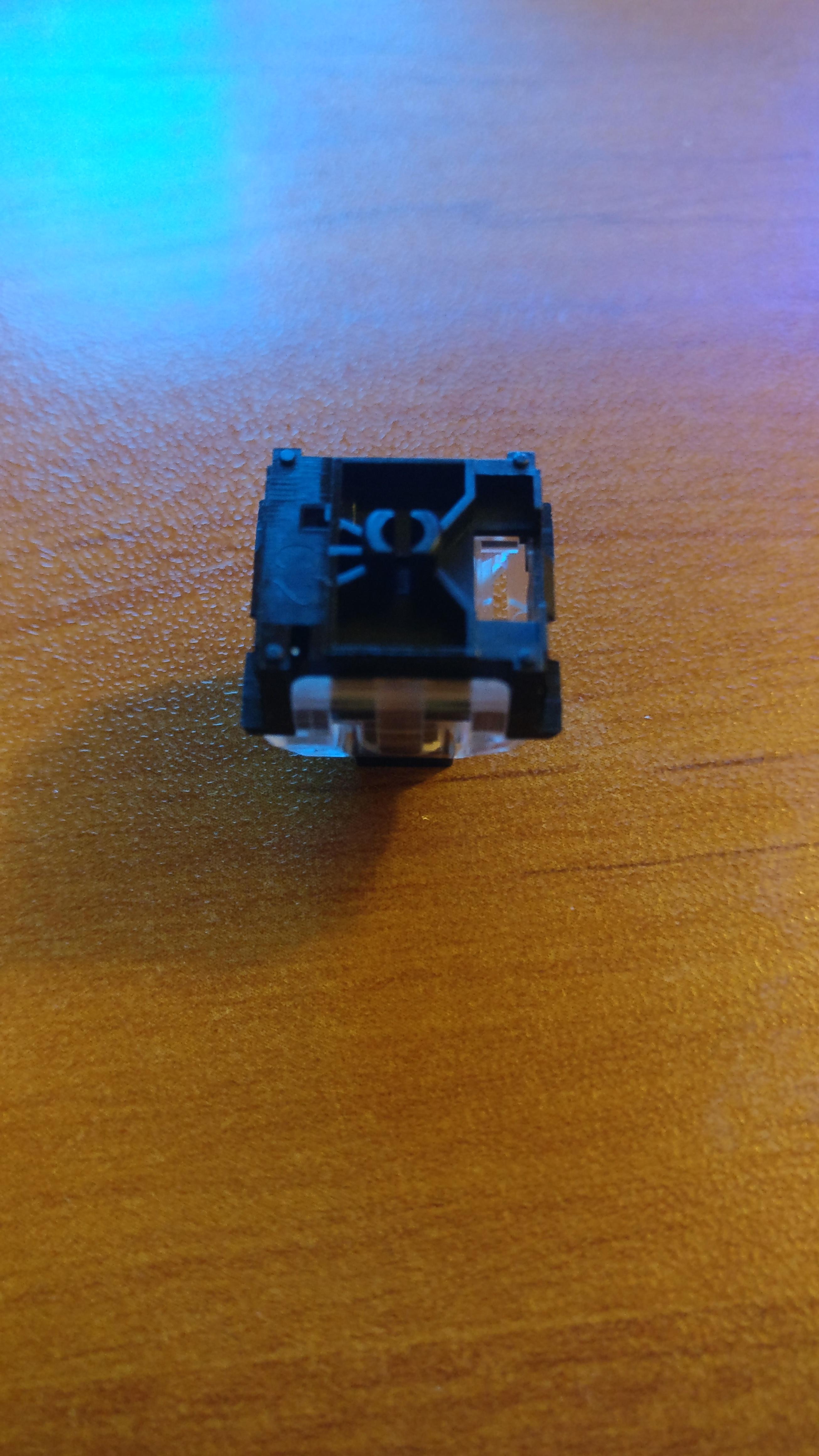
When the optical switch is not pressed, the stem pole is not down and the IR light can go through the switch and to the phototransistor.
When the optical switch is pressed, the stem pole is down and the IR light path to the phototransistor is blocked.
Those 3 components can be easily purchased:
- IR LED Everlight LKIR30102C-A02 (C390032 reference at JLCPCB or LCSC)
- Phototransistor Everlight LKPT30102B-A01 (C390033 reference at JLCPCB or LCSC)
- Just Google for the switches

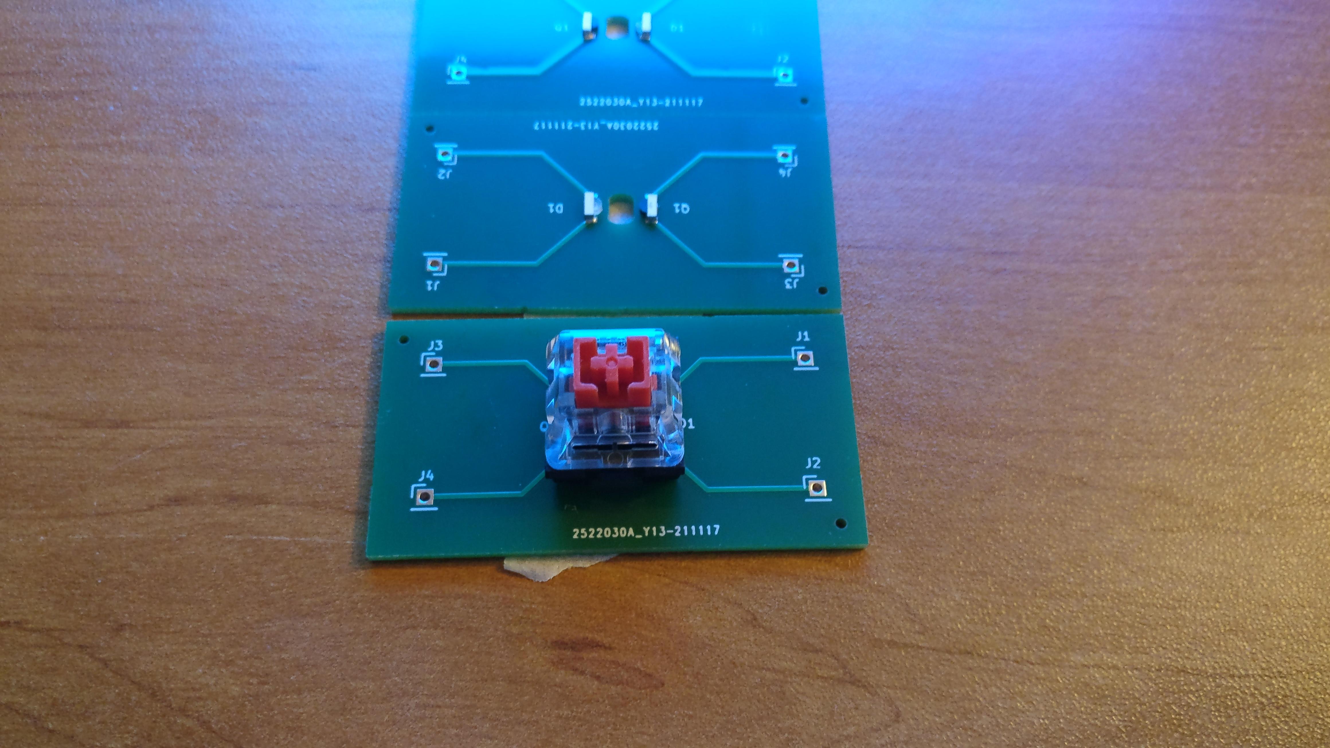
The nice thing about the IR led and phototransistor references given before is that you can make a full soldered PCB with them at JLCPCB, and this is what I did.
Simulations:
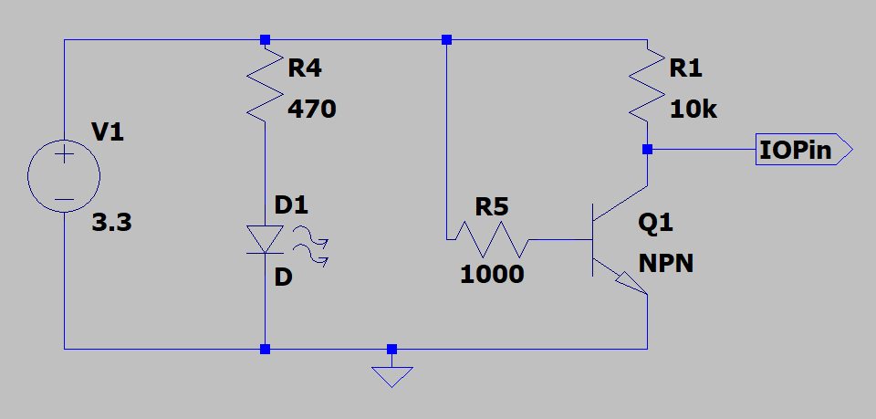
Wanted to check the theorical working of the technology so played a bit with LTSpice simulator.
A phototransistor is just a NPN transistor with its base exposed to light, as there are no way to simulate a phototransistor in Spice I just used a NPN transistor as a replacement.
When there is a good amount of current to the base of the NPN, this would simulate the IR light that goes to the base of the phototransistor.
Came with a schematic that work in theory.
IR led on:
IR led off:
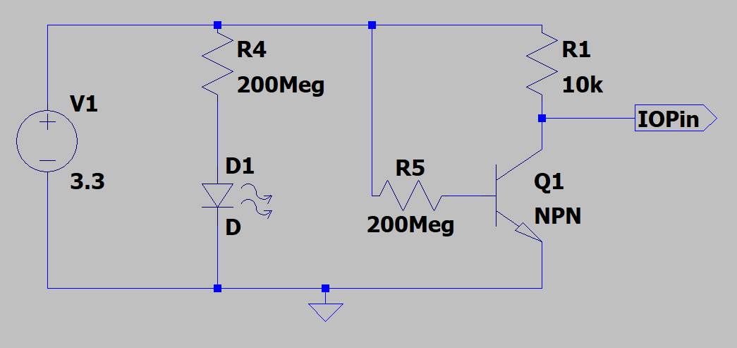
Came out with 470Ohms resistor for the IR led and 10KOhms resistor for the phototransistor.
Let’s see if it will work in practice and if we can do better.
Experimentation:
Breadboarded everything with a Teensy 3.2, a 3.3V device.
One of the IO pins is configured as output and drives the IR led through its 470Ohms resistor to limit current.
Another IO pin is configured as input, current is limited by a 10KOhms resistor. If sufficient light flow through the base of the PT (phototransistor) then this IO pin will register a low input, high otherwise.
Checked before that IR led forward voltage was indeed 1.2V(using a multimeter), very important to know to compute the amount of current given the resistance.
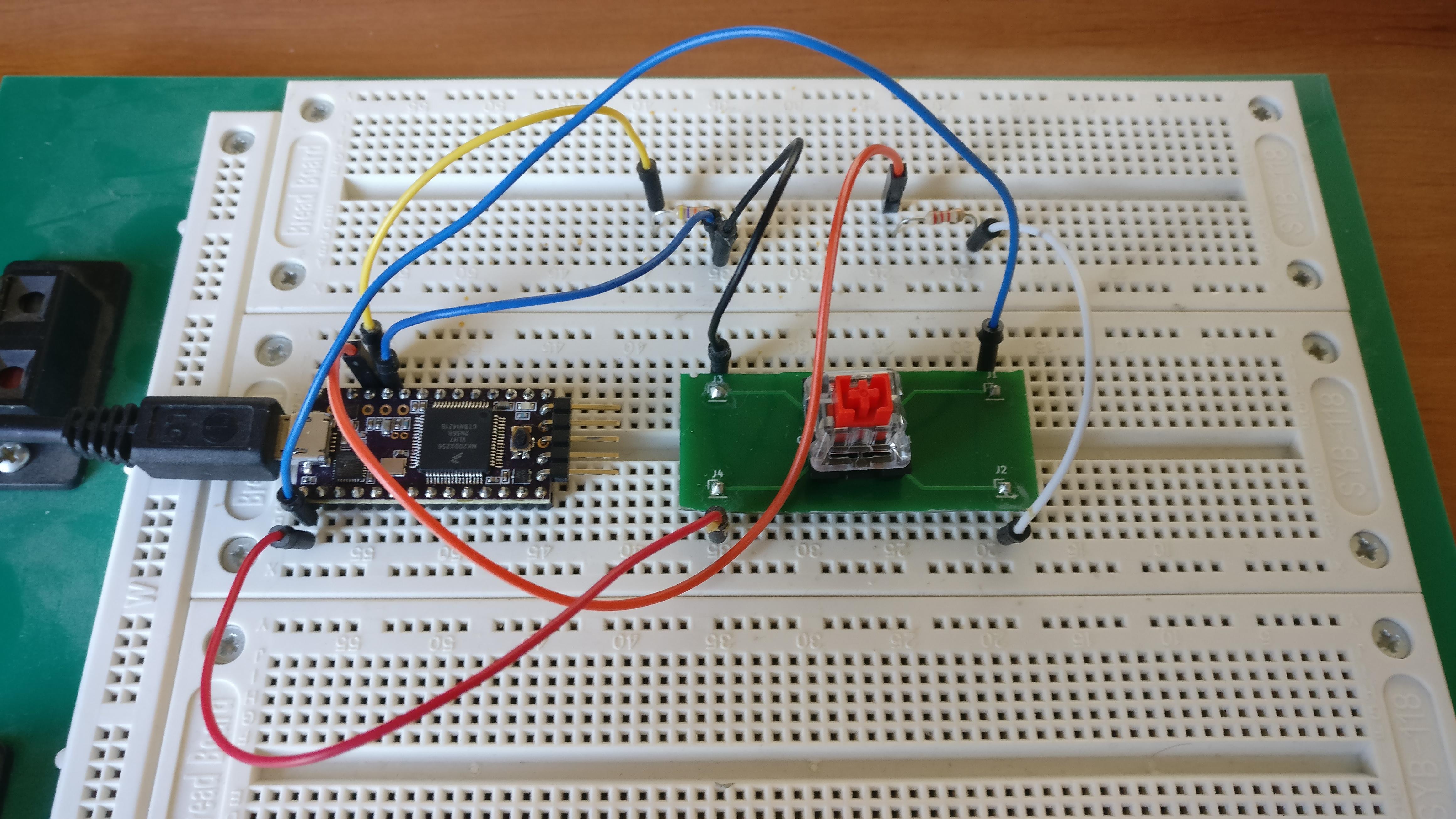
And it works!
Let’s see the current needed for the IR led and the PT.
IR led: A = (3.3V-1.2V) / 470 Ohms = ~4.5mA.
PT: A = ~3.3V / 10000Ohms = ~0.3mA
We are not too worried about the current driven by the PT, but more by the IR led.
Can we do better?
After some trials and errors I came with better resistor values that uses less current and still works.
IR led: A = (3.3V-1.2V) / 2200 Ohms = ~1mA
PT: A = ~3.3V / 47000 Ohms = ~70uA
With a 2.2K resistor for the IR led and 47K resistor for the PT current is much lower.
So much lower that we could think of driving several IR leds with just an IO pin ![]()
If you want to experiment yourself with an ATMega MCU, keep in mind that it is 5V and the resistors values are calculated for a 3.3V MCU.
This is the current that is important, so just compute the new resistances based on the currents I obtained in the results (~1mA for IR led and ~70 uA for PT).
This is all for now folks !