We are at moq!
1 Like
The group buy will most likely close around wednesday, invoices will go out then.
How many orders do you have?
5 total. The group buy is also closed now will close when I get all of my invoices paid. I may do a second round of the group buy or have it up on a shop.
Any updates to the timeline?
Yep @8o7wer!
Do you have a update on this yet? 
Sorry for not updating sooner, everything is ordered and on its way to me. I had some weird stuff with jlc support so hopefully everything ends up ok.
They are shipped out, thank you to everyone who ordered!
Great work! Looking forward to trying to re-learn how to type on this thing 
How are you guys programming these? I’d love to see your configs/layouts if you’re using QMK. I’m still rounding up the parts to put it together right now.
I’ll probably go with the kbdfirmware first as it’s easiest to configure it. But then again, I don’t know if @8o7wer has a json file or not yet. Probably try them on Discord and ask about putting it here if they have it.
I still need to grab some diodes and mod the switches as well as get caps figured out for it from my grab bag sets, but I might do the build on stream once I have the parts.
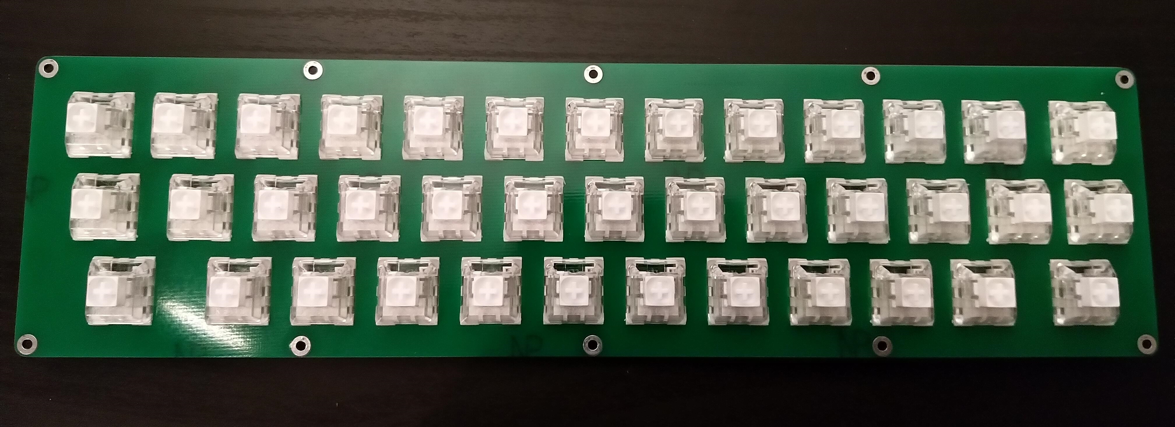
Quick question: I’ve started soldering, but when I was about to solder in the switches in noticed that the holes for standoffs/risers in the switch plate is blocked by the pcb. 4 of the standoff holes are partially blocked. The PCB almost seems like it’s upside down or something, but I can’t really find any other way to merge the switch plate and pcb together.
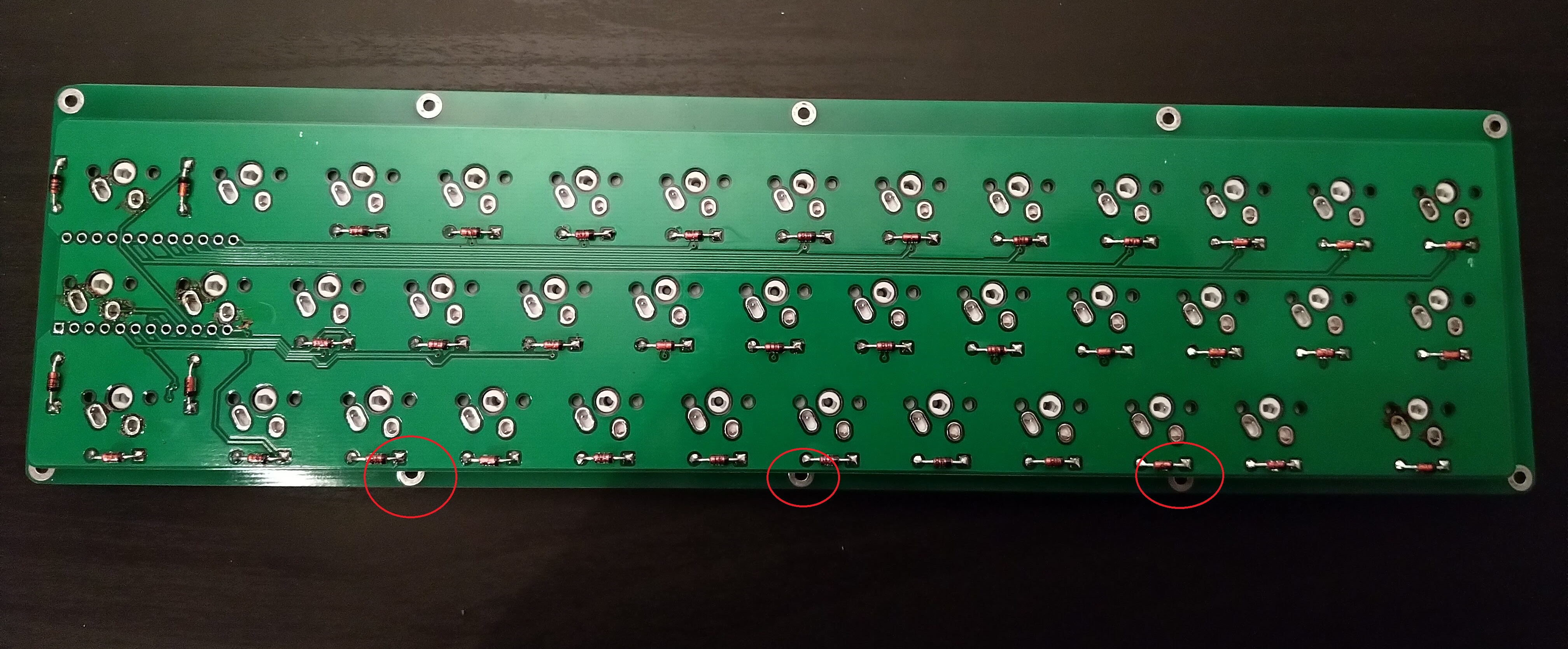
Have I overlooked something or done something wrong here?
EDIT: Just popped out all the switces and tried reorienting it so that the switches go in on the other side of the pcb. In this configuration the riser holes clear the pcb, but the holes for the switch connectors don’t line up with the switches. Based on this I think there’s only one way to orient the pcb, which will mean it interferes with the holes for the risers.
Just made a preliminary QMK config for the 30wer. I haven’t tested it on a real board yet (due to the issues above), but shorting pins on the Pro Micro seems to give the correct keys.
It can be found here, if anyone is interested (on the 30wer branch): GitHub - FSund/qmk_firmware at 30wer
EDIT: Pinging @jmassaglia, I saw you were looking for a QMK config.
1 Like
Sorry for not responding sooner on those issues, I didnt have the funds to do a build at the time of shipping out the pcbs as I had used up all my money for spending on kbs running the gb (I had a net loss) Ill look more into your issue tomorrow with some of my extras though.
No worries!
I can probably make the pcb work with some dremel-work, but I just wanted to see if I had misunderstood something before I started modifying the board too much.
I have had the same issue, tried turning the plate and board around as much as I could and to no avail. I think that in this set the plate holes were offset from center. If it was centered correctly, it should work. Right now, one half completely fits and the four corners fit without changing anything. (it is possible that only three corners fit, but I think I was able to do all four)
I’m actually working on a build video where I plan to address this issue. (my first half was modding the switches. Retooled blacks with 3204 and switch films)
@FSund I wouldn’t alter the PCB, but rather the standoffs. If you have hex shaped standoffs, you can file them down with little worry. I have done this once already and will do it for the three offset ones in my video. You could use a dremel cutting disk as well, but that’s less precise. Plus, if you mess something up, it’s only a standoff and not your pcb.
Looking forward to the video.
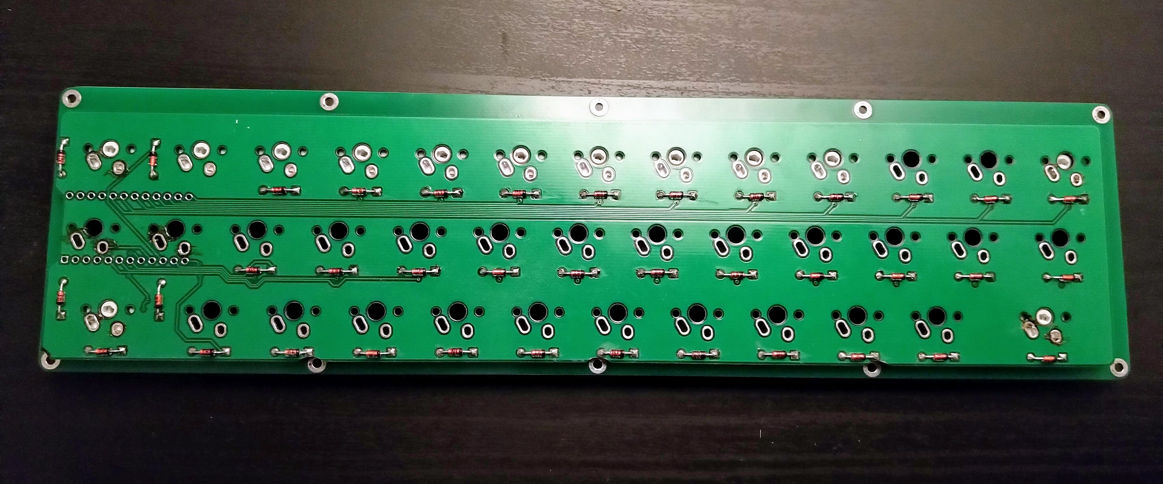
Since you confirmed my suspicions, I just went ahead and did the mod of the pcb. There’s not really anything important going on (electrically speaking) in that area anyway as far as I can see, so I think it should be alright (as long as you don’t do too much damage to the diode holes/pads).
Here’s the result (the holes look a bit off-center due to the camera angle):
Sorry about the issue with the pcb, I have the issue with mine too, I dont know how that got past my checks.
Also watch the traces on the other side, if you cut into the silkscreen of the diode you cut into the traces for the bottom row.
You are of course correct, I did end up cutting into the traces for the bottom row! But I fixed that using a wire via the diodes. I didn’t think there was a trace there, but it was hidden beneath the silkscreen.
Here’s my finished board
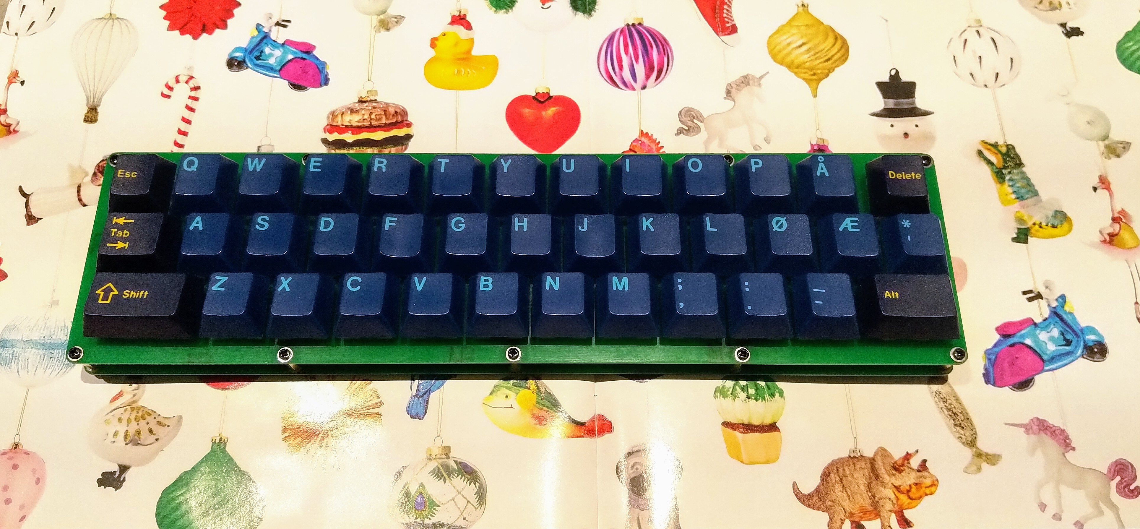
I’m thinking of making a 3d printed case.
1 Like
I had some issues with getting QMK to work correctly. Uploading the .json from KLE didn’t work right so I had to edit the way the wiring was done because one of the rows was offset by a column, making Z not work. I also had to do some fiddling with the .c files and layout files, etc.
I have uploaded the hex to my github as well as the keyboard folder needed for your QMK directory if you’re planning on compiling yourself. It all seems to work now. I’m sure the layout isn’t great for what people want, but if you can do the make, you can edit the layout values easily enough. No pics yet as I have only soldered the diodes and socketed the pro micro.
Now, one thing to note about the document that came with the pcb is that it is slightly off. Or more to the point, there is some ambiguity, I think based on your pro micro. On the document, it shows C9 and C10 connected to SCL and SDA. I thought that this corresponded to D2 and D3 respectively. This is not the case with my pro micro, which is this one: Pro Micro Board ATmega32U4-AU for Arduino (Black) – kookye.com
In the case of my pro micro, it’s D1 for C9 and D0 for C10 as it shows on the paper. If you’re messing about with the QMK builder on KBfirmware builder, it needs to be numerated starting with 0 on all columns and rows. This offsets it by 1.
My Github link is here: GitHub - Saucks/30wer
I don’t pretend to know hardly anything about qmk. This is just how I got mine to work.