Build #33: HBCP
In previous build logs, I’ve noted my love for the 1800 layout and its variations. If I were to tabulate the time I’ve spent with various boards as my daily drivers, the bulk of that time would have been spent with the 1800-layout kbd19x (Build #11) and the hybrid 1800/65 southpaw layout EXT65 (Build #29). I’m happy to build just about any board, but when it comes to using one, I find I’d rather err on the side of more keys than more QMK layers. Perhaps remembering all of those Emacs keybindings for a few
decades used up all of my long-term memory?
I’m not sure exactly when I stumbled across the IC for the HBCP by Hineybush, but as soon as I saw it, I knew I had to get my hands on one. The IC had a pretty long gestation period, but the GB ran in September 2019, production was quick, and fulfillment is in progress right now. Often when I receive a build kit, it’ll sit on my shelf for a while as I build up the fortitude to lube yet another batch of switches.
But not this one. Will the HBCP clear the high bar to enter my daily driver rotation? Let’s find out.
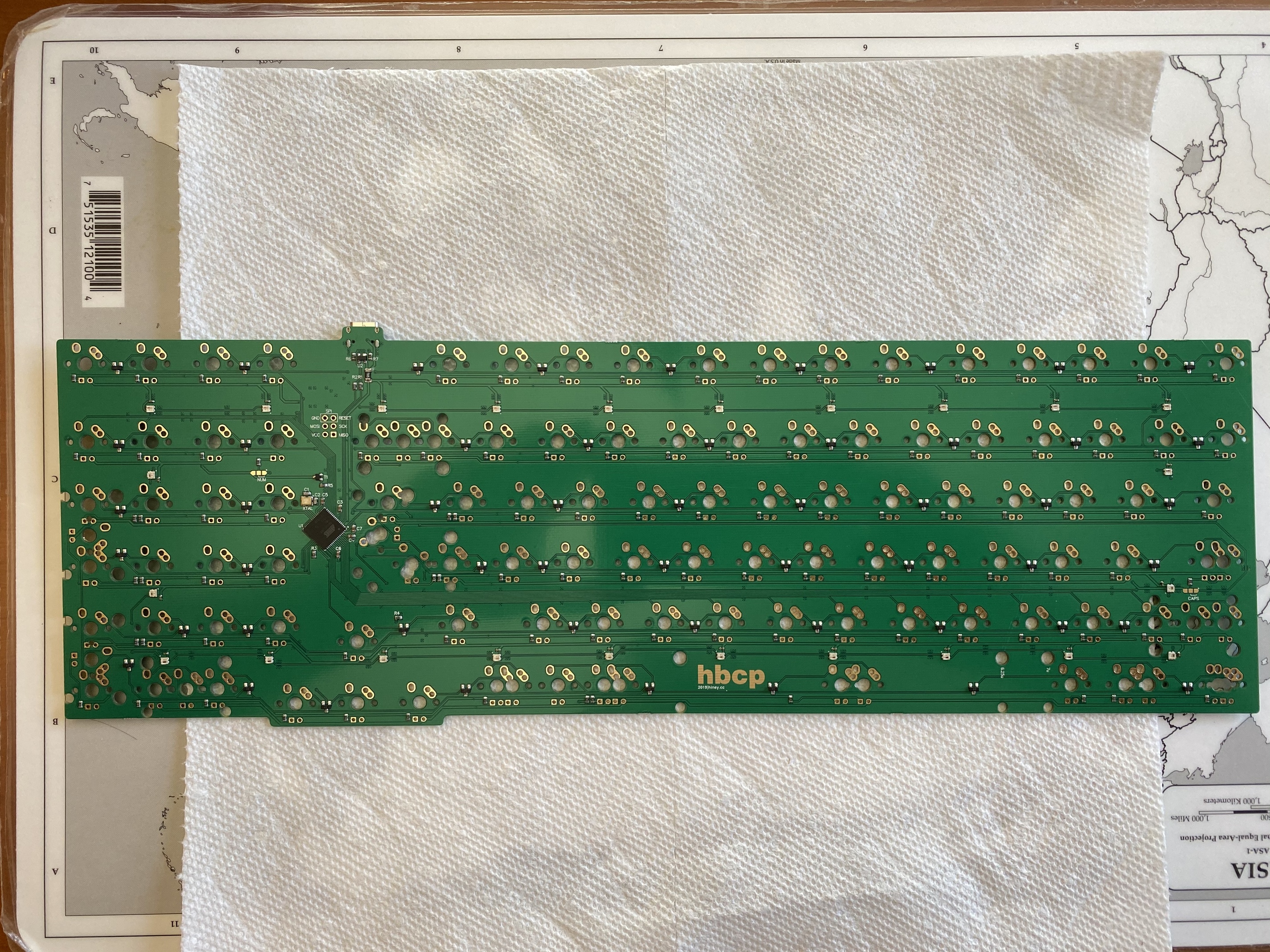
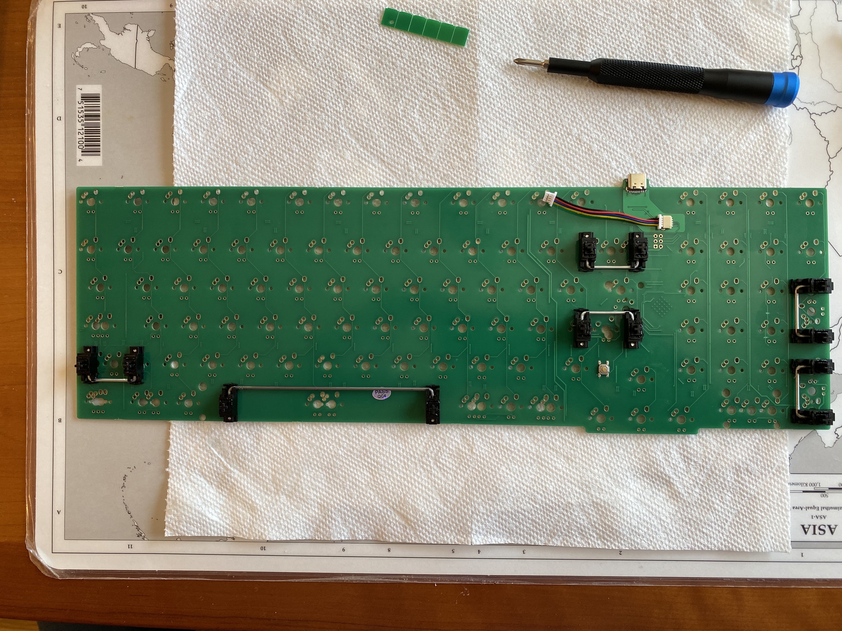
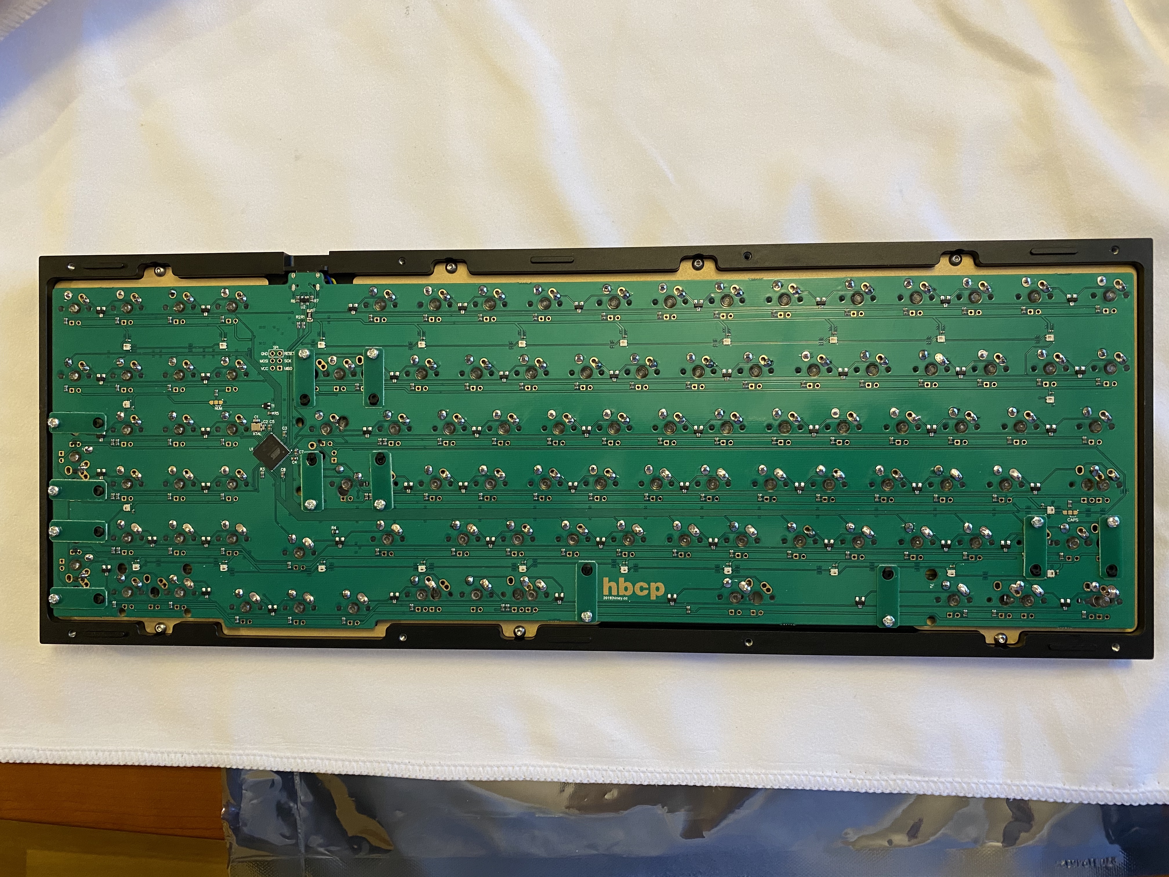
Let’s start with the PCB. The microcontroller on the HBCP PCB is an AT90USB1286, and the PCB
supports USB-C. The PCB supports a few different choices for layout: split left shift, split numpad keys, and 6.25u vs 7u bottom row.
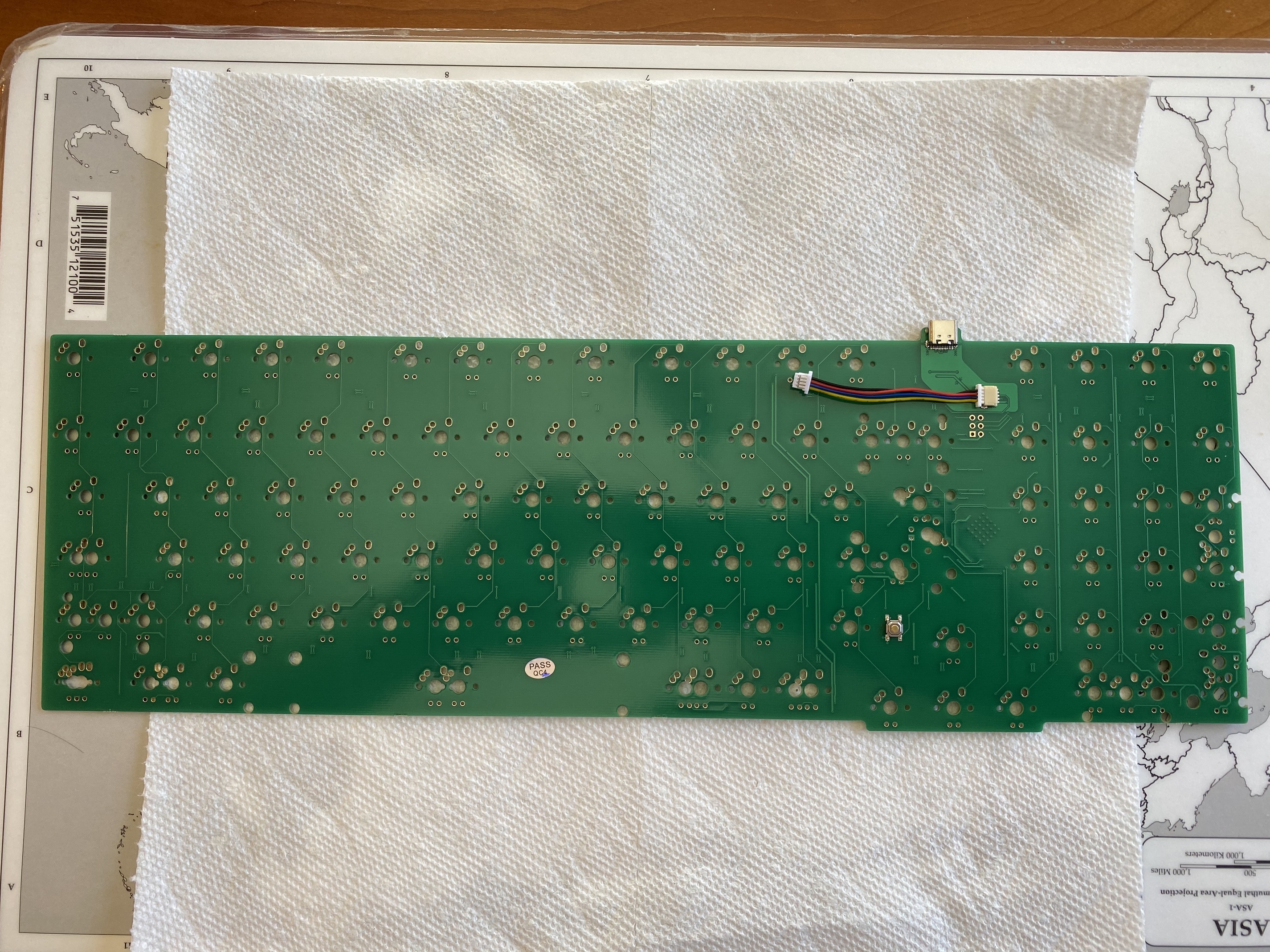
Flipping it over to the top side, we see a couple of interesting features. First, there is a preinstalled connector cable for a daughterboard that hosts the NCS indicator lights. Second, the reset button is on the top of the PCB, not the bottom where it usually resides.
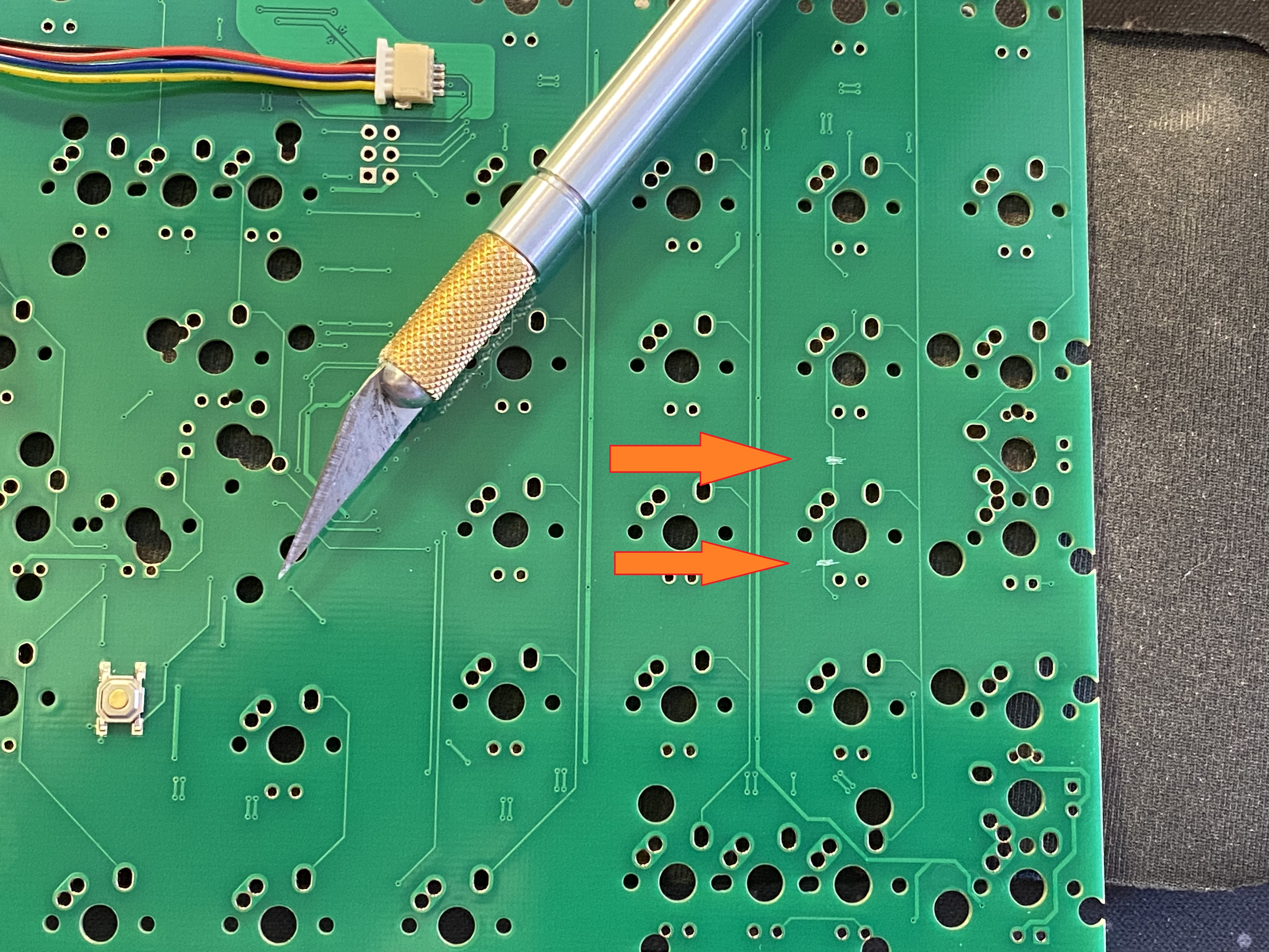
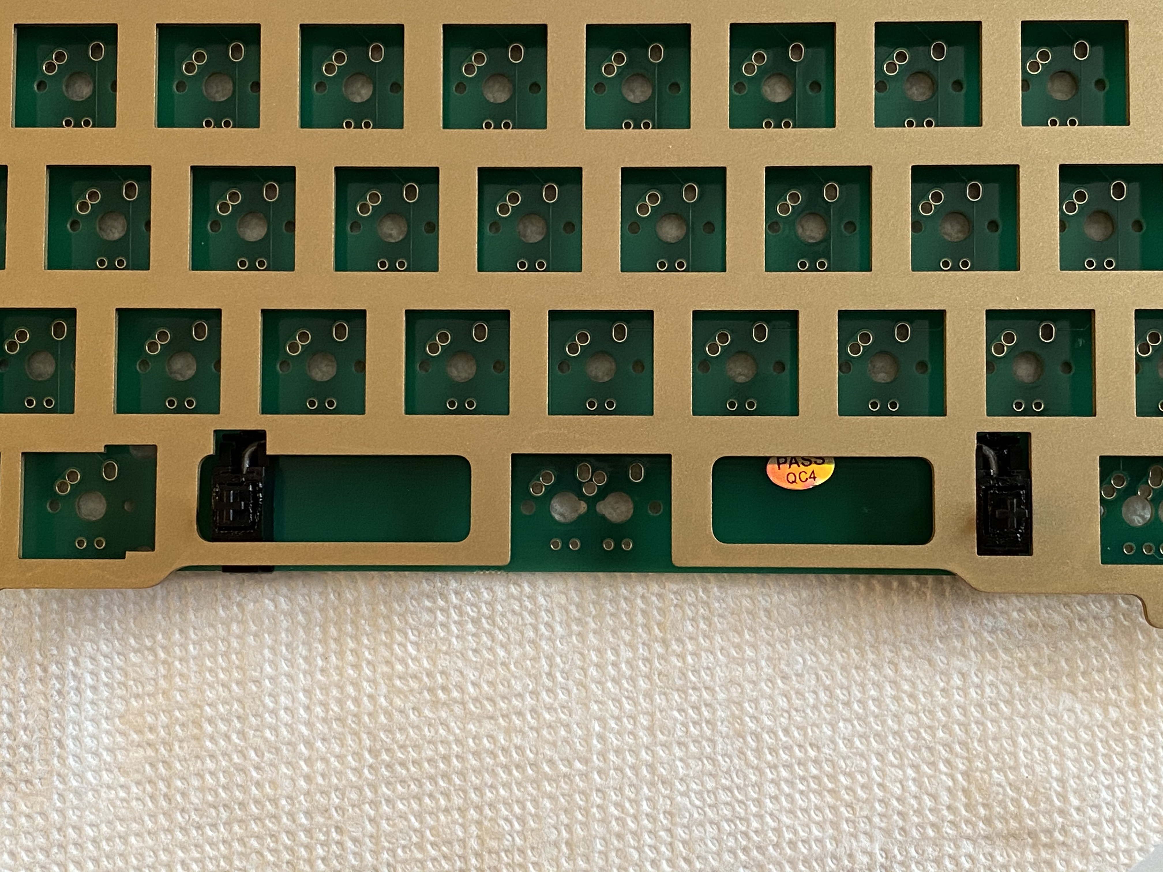
Right after shipment, a problem was discovered with the production PCB - hitting the 6 key on the numpad resulted in all of the keys in that column registering keypresses. The fix turned out to be straightforward - cut a specific trace on the PCB in two places. I hadn’t done this before, but it’s trivial; get a box cutter, Xacto knife, or razor blade, and scrape the tip of the blade back and forth across the trace until you feel that you’ve severed the trace. You can test the numpad 6 with Switch Hitter, before and after, to confirm that you’ve successfully cut the trace. The following photo shows the two locations where you need to sever the trace.
If you’re still freaked out by doing this, let me give you another analogy. You know those gift cards or lottery tickets where you have to scratch off that stuff to reveal the code or prize? It’s like that, but instead of scratching off an area, you’re scratching off a line.
Cutting that trace also severs connectivity to three of the underglow RGBs. If you want to restore that functionality, you’ll need to solder a jumper on the PCB, but since my case was aluminum and I don’t need or want RGB, I didn’t bother.
Before we go further, we’re going to want to flash the PCB so we can bind RESET to something. I downloaded the HBCP hex from the caniusevia website, flashed it with QMK Toolbox (remember, AT90USB1286 controller!), fired up VIA and changed some bindings (super easy to change layouts, which I appreciate - still can’t do mod tap yet, but VIA is getting closer and closer to something I could
regularly use). But I’m sold on VIA for at least the basic pre-build config to get RESET where I want it, my QMK setup is complicated, and I don’t always want to take the time at the beginning of the build to make a custom hex just so I can get RESET functionality.
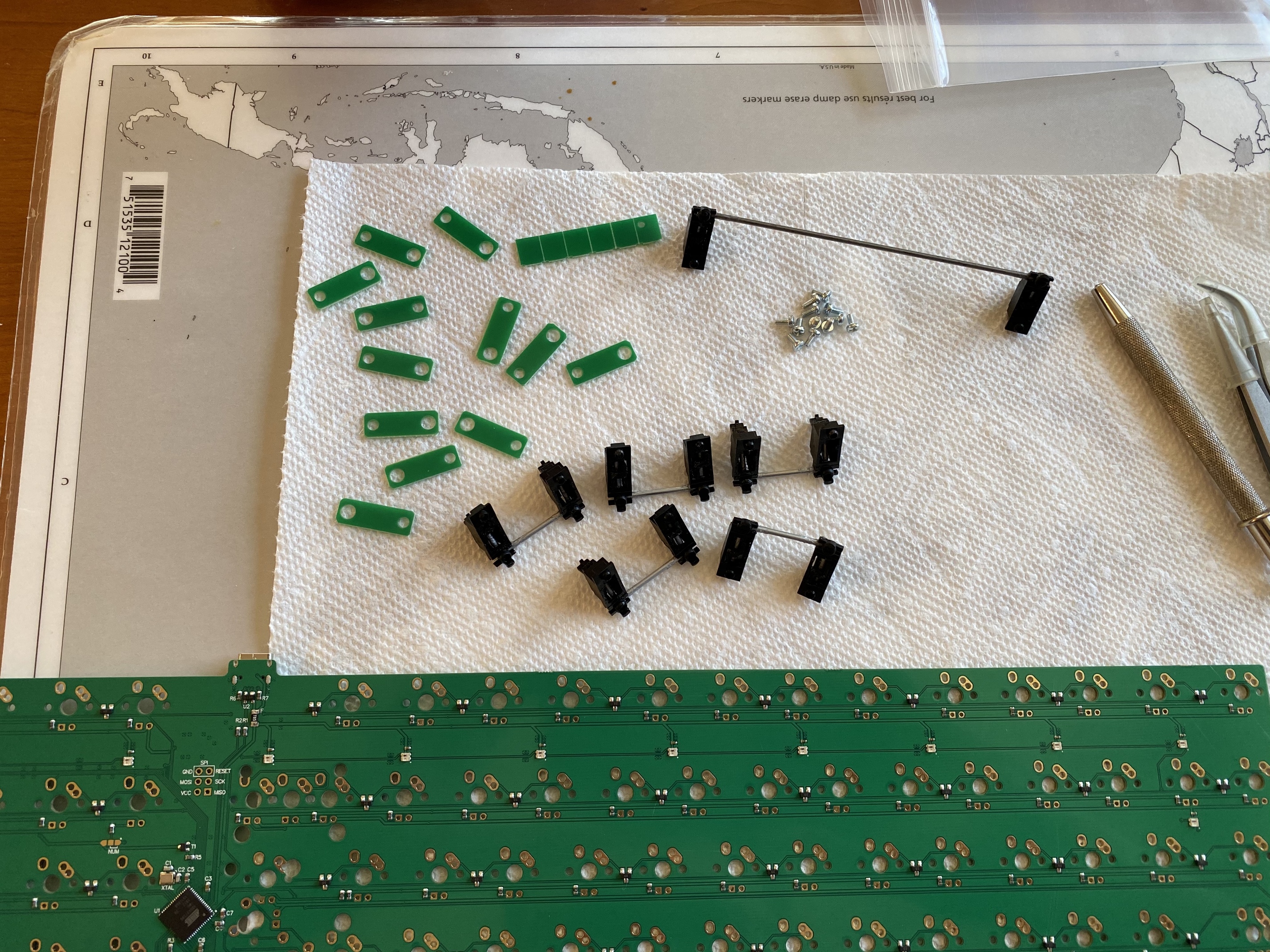
Next up: stab modding. That all looks pretty standard. Hey, wait, what’s that bit of green PCB material?
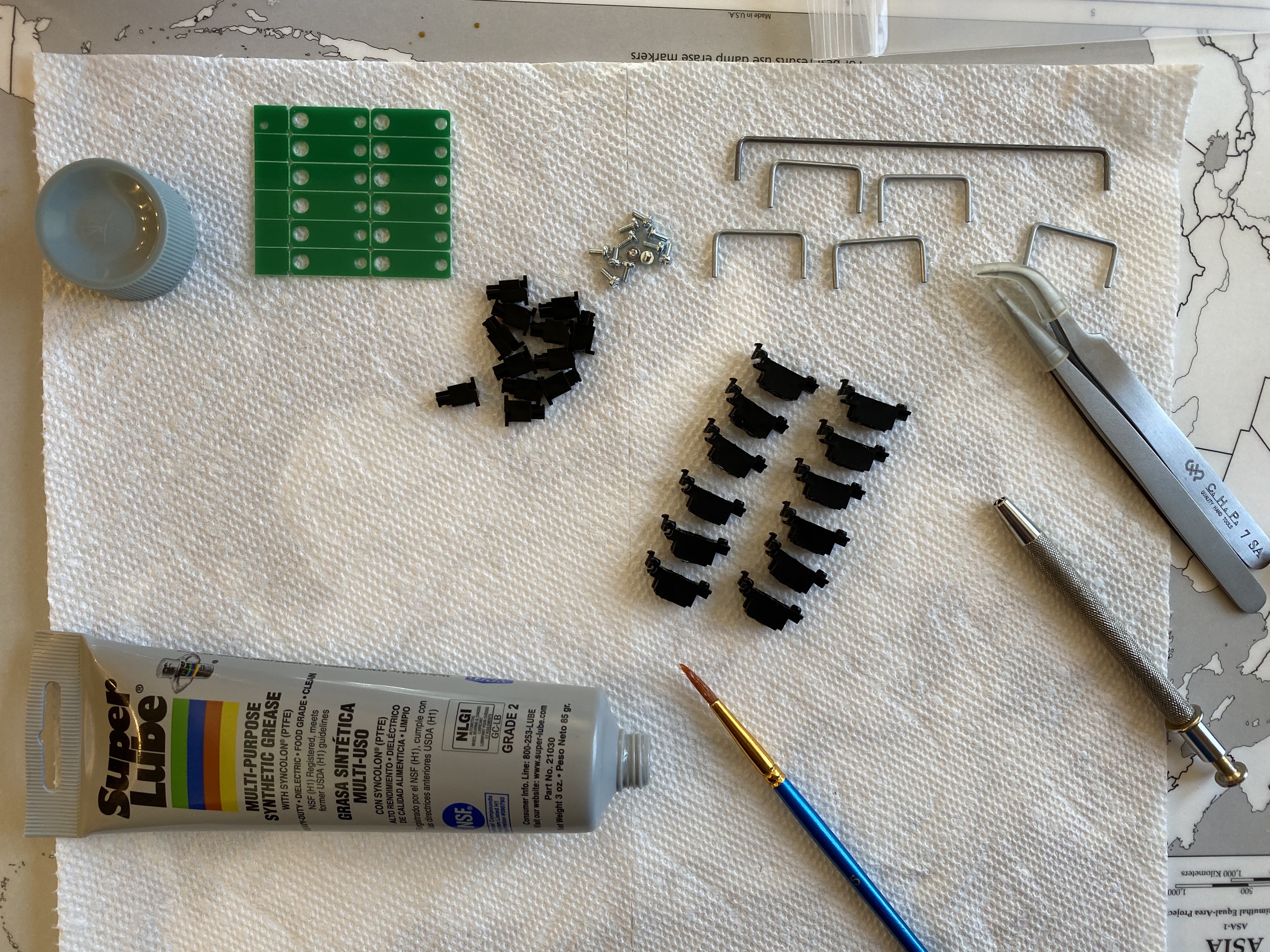
The HBCP PCB is one of Hiney’s “thinboi” PCBs, 1.2mm in thickness instead of the usual 1.6mm to give additional flex (at least if you choose a softer plate material). However, stab housings are designed to fit a 1.6mm thick PCB, so they will wobble if installed in the usual way on a 1.2mm PCB. Enter the stab spacers - little pieces of FR4 with cutouts for the clip hole and screw hole of a stab housing. Once you’ve modded and lubed your stabs to your satisfaction, you break the stab spacer sheet into individual stab spacers along the scoring lines.
From the top side of the PCB, nothing looks different about the stab installation.
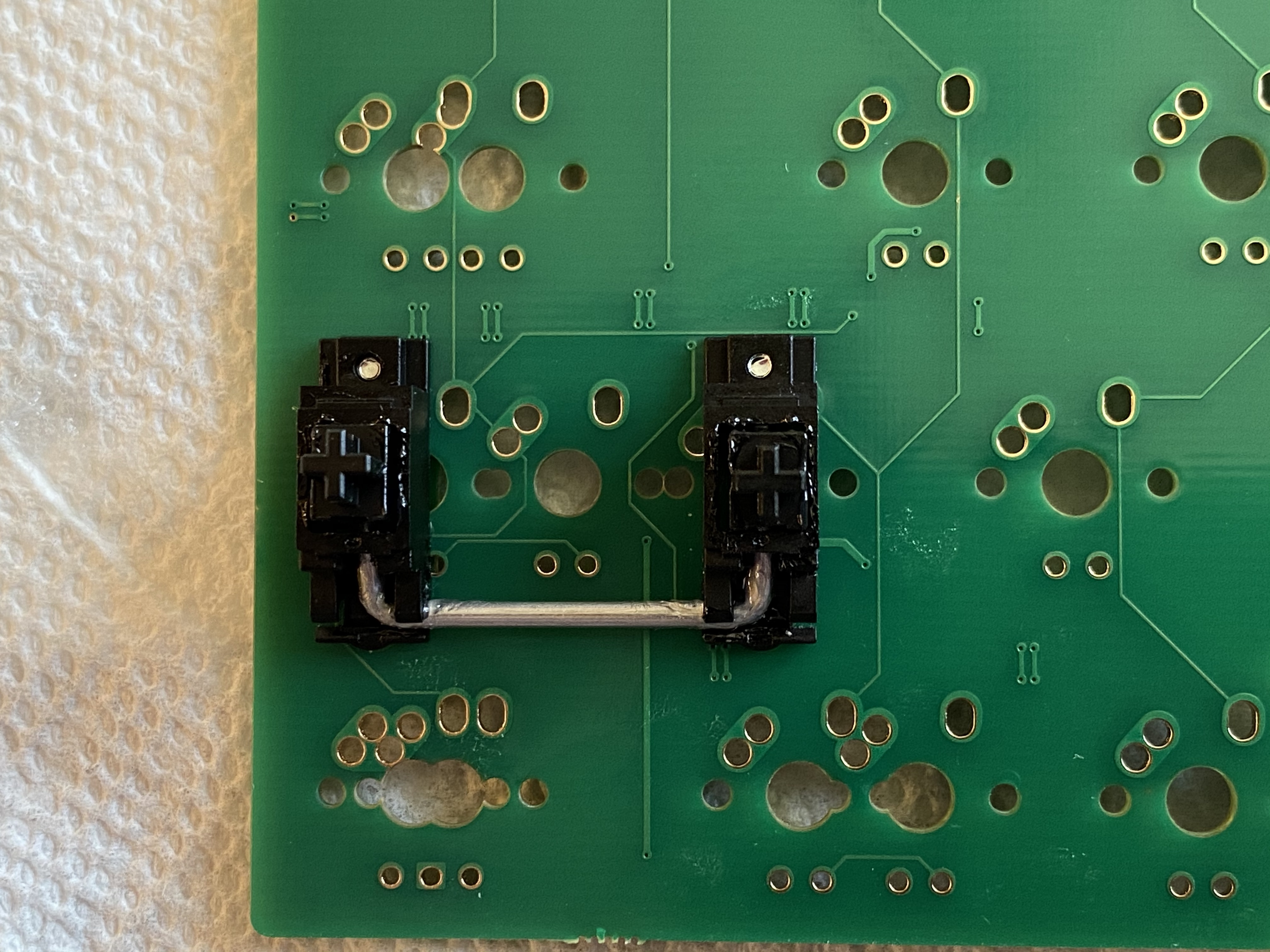
From the bottom, however, we can see the stab spacers in action. Hiney provided a video showing how to install these - the “trick” is to slide the stab spacer under the stab clip first before seating the stab housing into place. Looking at this next photo, it looks like the left spacer is not quite as well wedged under the housing clip as the one on the right - but as they say in basketball, no harm, no foul.
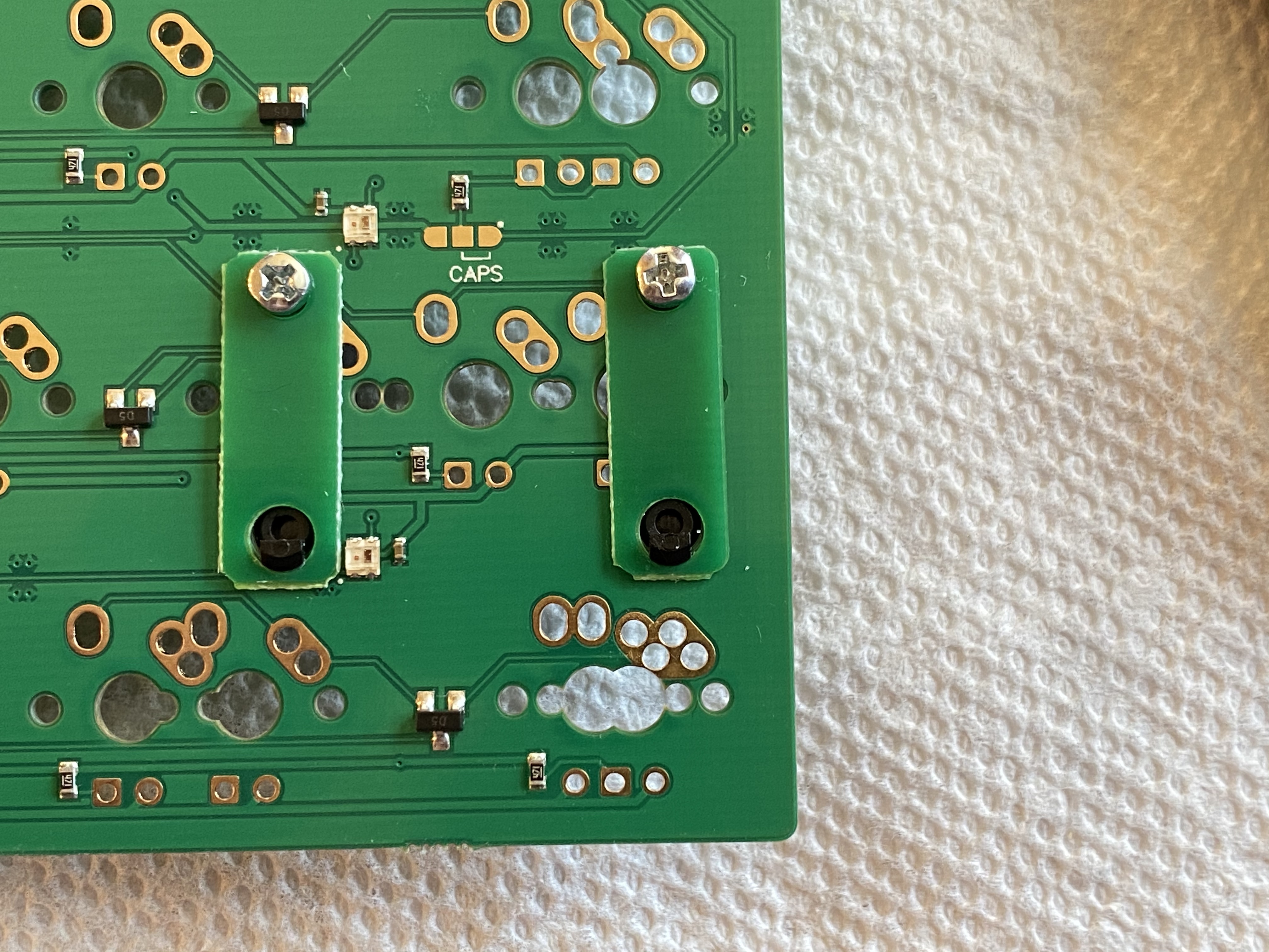
Here’s all six stab spacer pairs, after installation. Note that a couple of the stab spacers pass over surface mounted components on the PCB - the spacers are flexible enough that you’ll be able to bend them over the components, although it does make the stab installation a bit more involved than usual. A couple of the stab spacers took me a few tries to get seated properly. As with most issues in a build, patience and persistence are your friends.
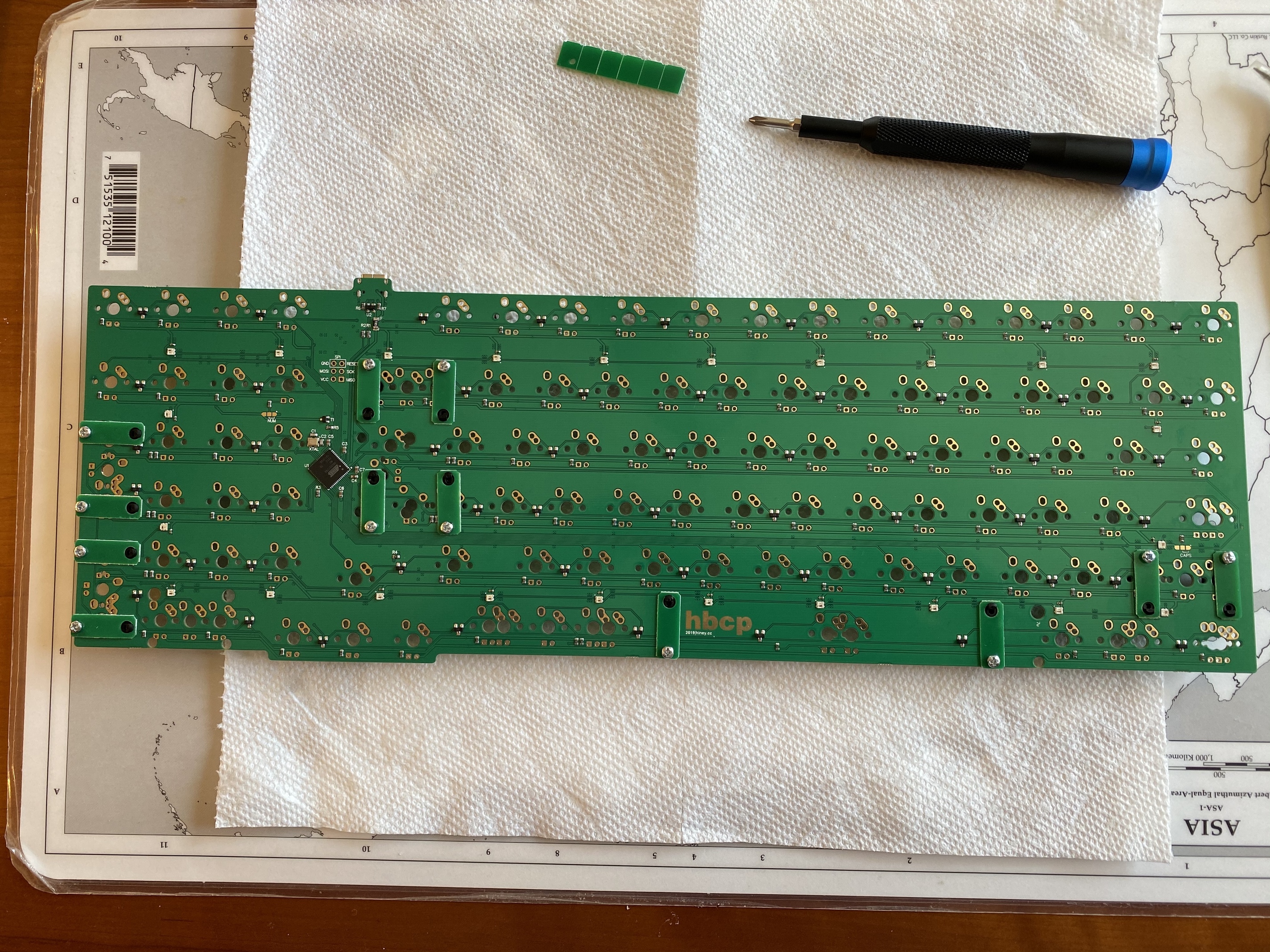
Everything looks good from the top side.
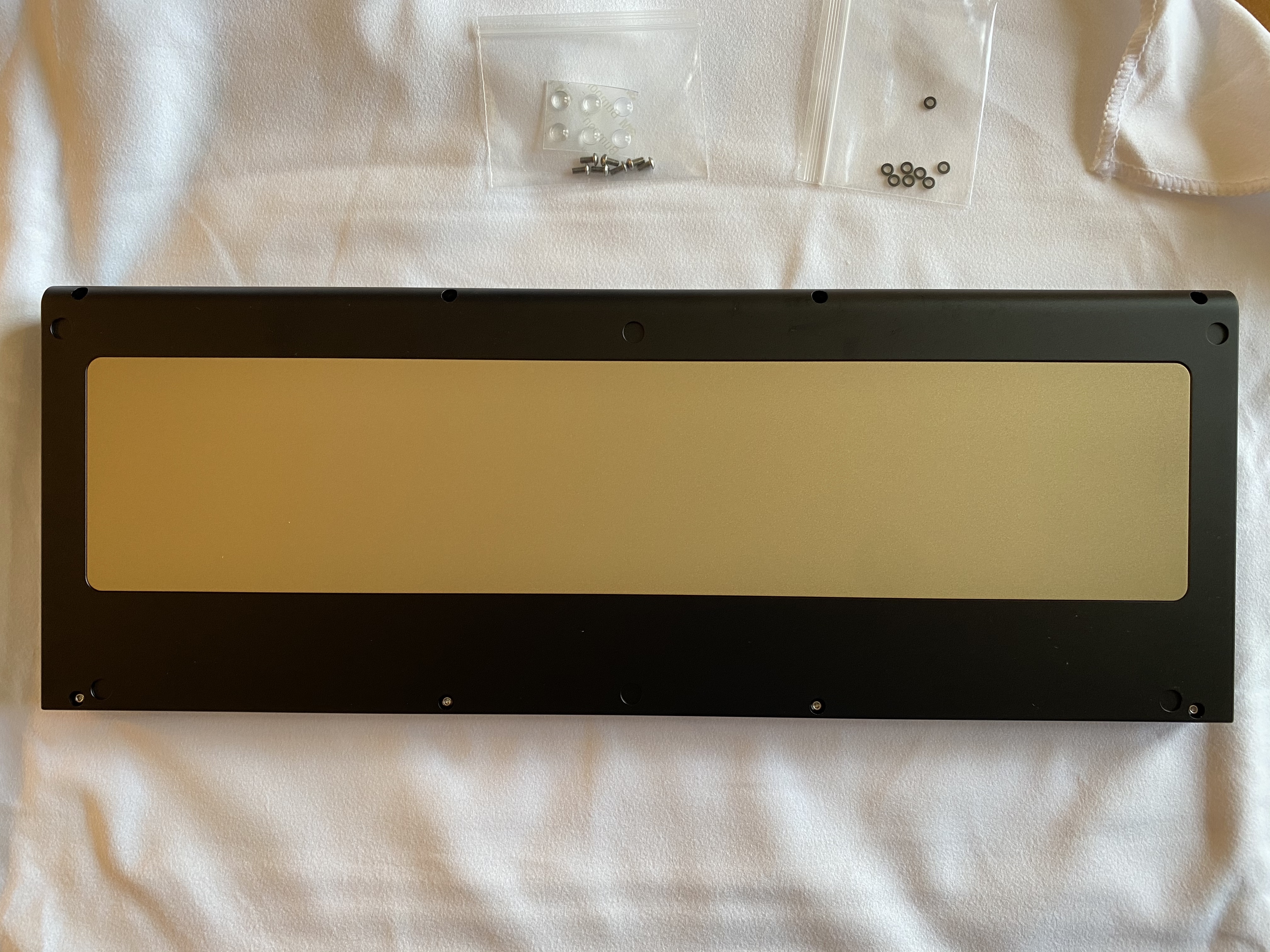
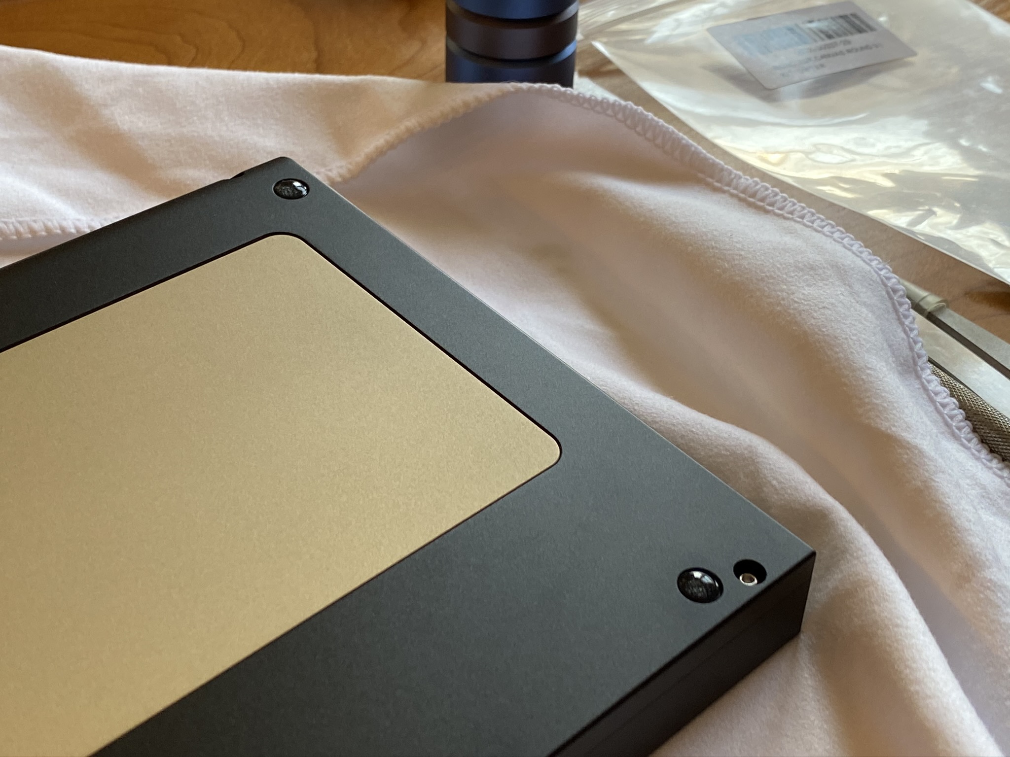
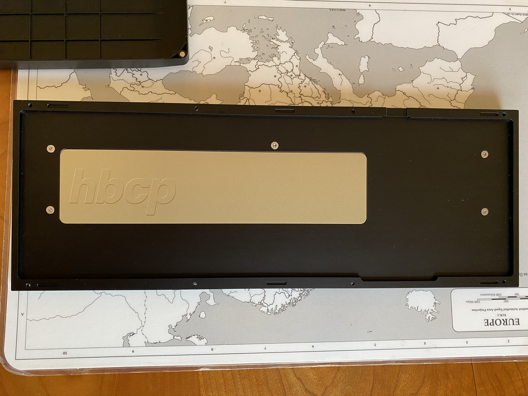
Time to take the case part so we can get to the plate. This HBCP is black-anodized aluminum, with a matte-finished brass plate, and the hbcp logo engraved on the interior left side of the base weight. Note the full-size “Hiney rag” that came with the kit, for protecting the case and wiping the case down. I appreciate these kinds of details.
The underside shows the base weight, clean and simple with no exterior engravings.
Show off those curves.
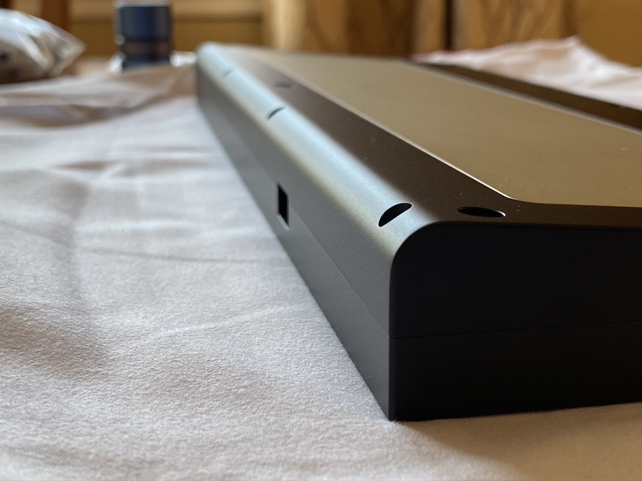
Might as well install those bumpons while we’re here. The bumpon cutouts are a bit deeper than most boards I’ve built, so the board will sit closer to the desk or deskmat with bumpons installed.
After removing the case screws, we can get a good look at the case interior. Five screws hold the weight in place. Also note the slot cutouts along the edge, to properly align the case top and bottom - another detail I appreciate.
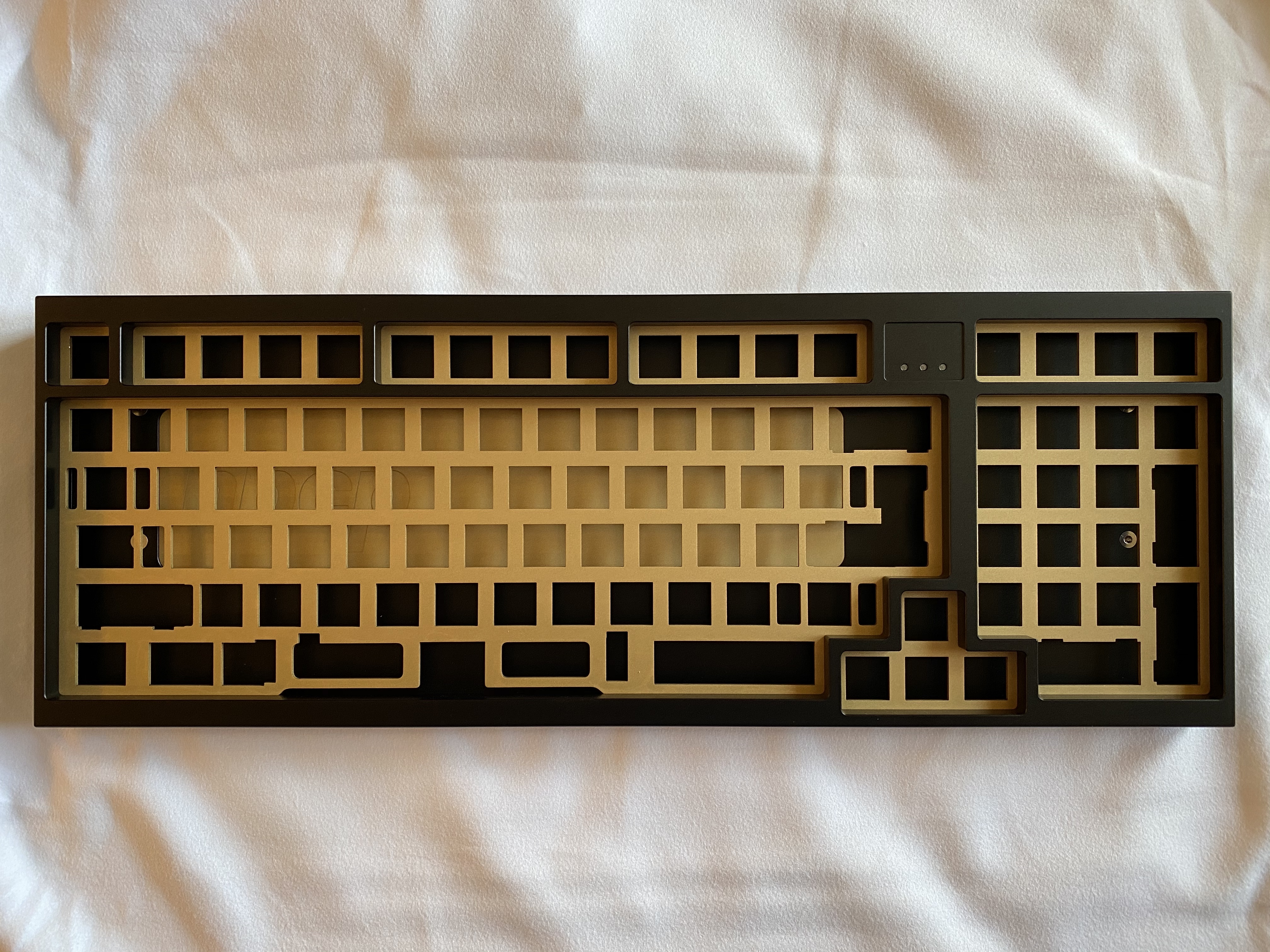
Moving our attention to the case top, the brass plate is top-mounted, with a number of relief cuts, so we won’t be doing any Sorbo strut mods here (parenthetical aside - I feel like more and more of my recent builds are using plates with relief cuts? Just an observation.)
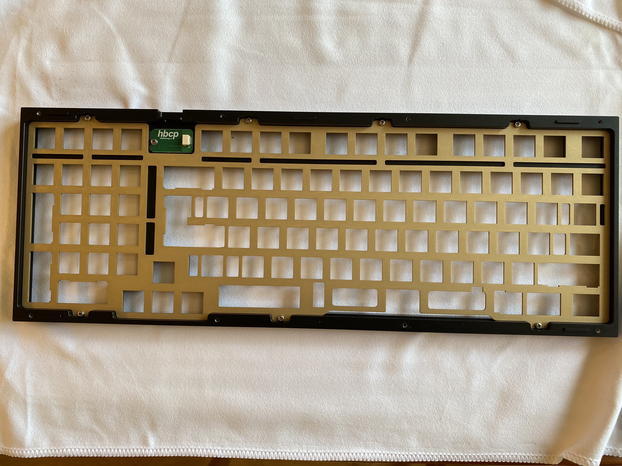
Removing the plate screws, we’re left with the top, and the preinstalled indicator light daughterboard.
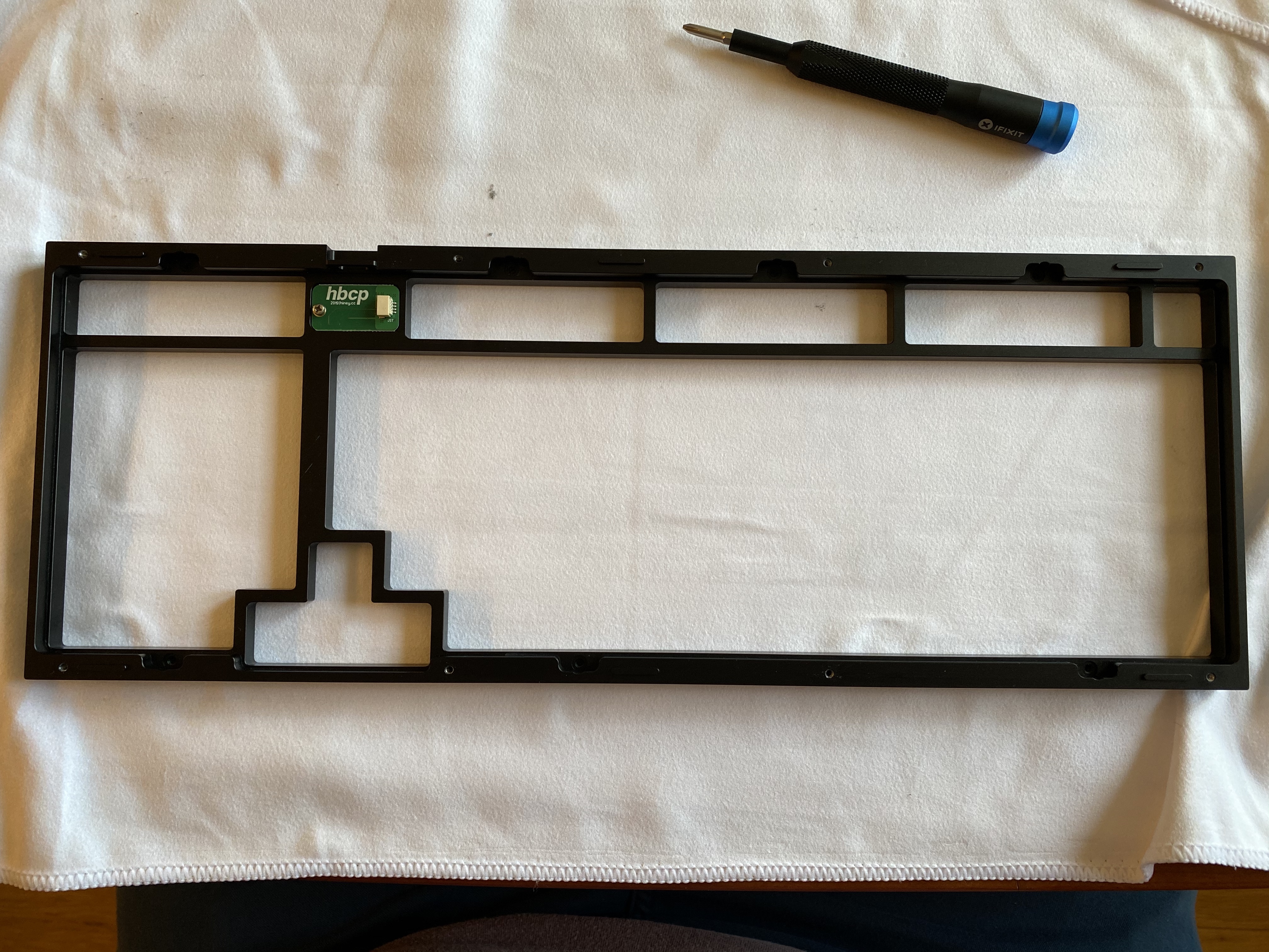
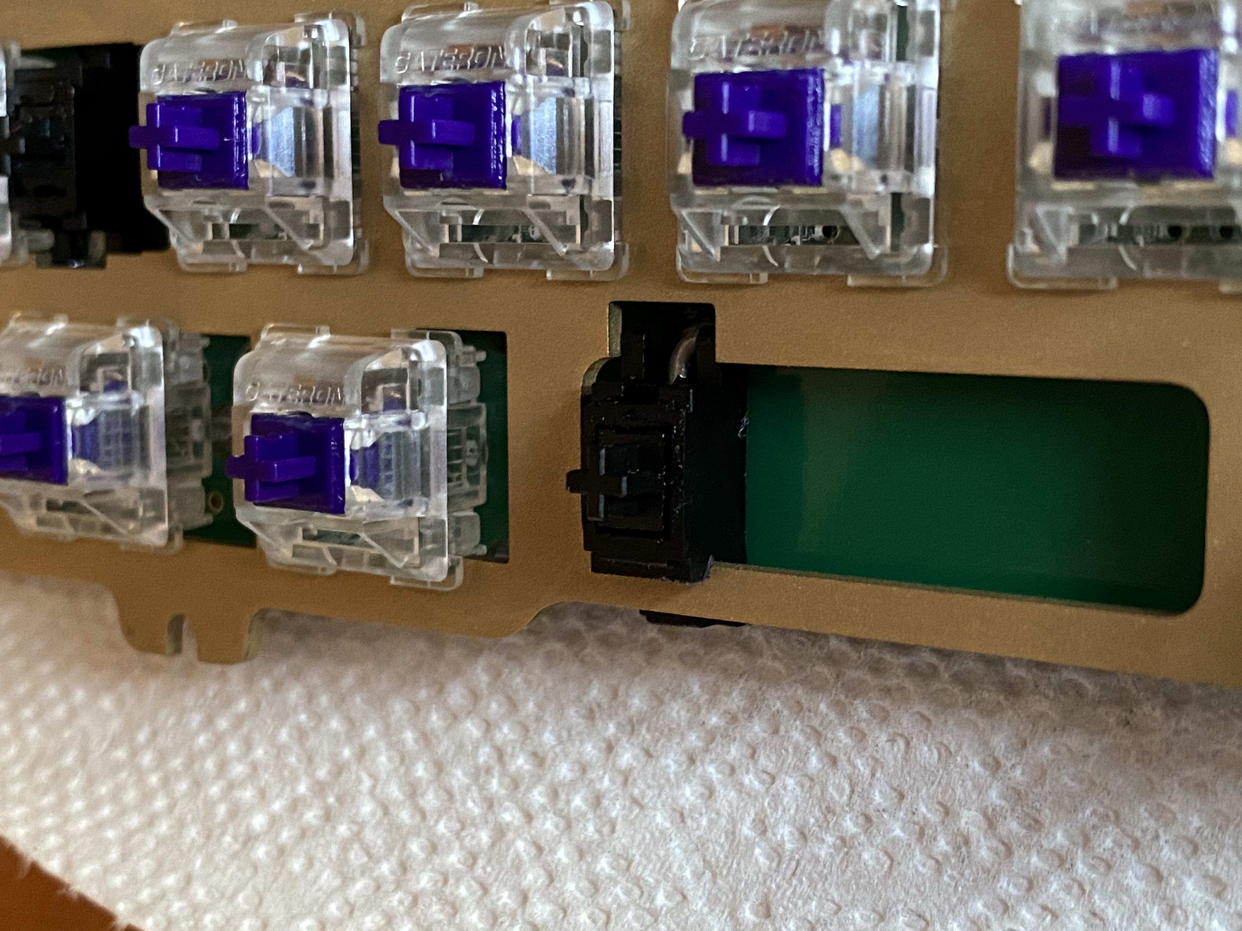
Sometimes I wish I had a comfortable seat on the WKL train. Do you see an issue here?
It turns out there was an oversight in the plate design - if you’re doing a 6.25u bottom row layout, the cutout for the spacebar’s left stab housing isn’t deep enough on the bottom edge, so the plate can’t seat properly. After thinking about this for a bit, I figured there were three options:
- Dremel the plate to make room. It’s a nice-looking plate, though, and I don’t want to scuff it up.
- Switch to 7u bottom-row, for which the cutouts are correct. No Win key, though?
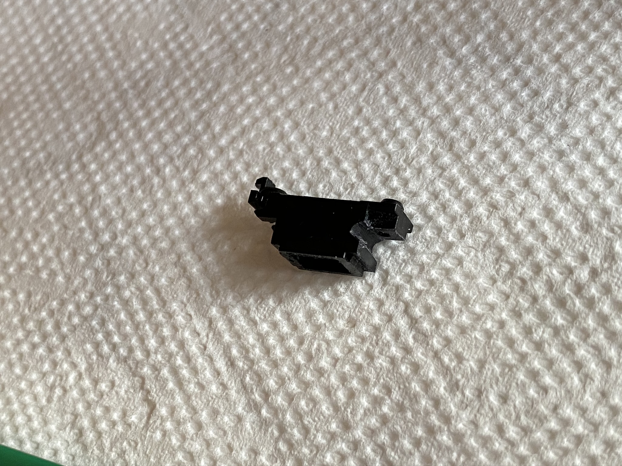
- File the left stab housing into conformance with the plate.
Option number three it is! With a needle file and a bit of patient filing, you can make it work. I found it easiest to lightly rest the flat side of the file on the screw housing while using the edge of the file to start a groove - this will file away a bit of the screw housing surface, but that’s not really an issue. Once the groove is started, it’s just a matter of keeping the file level and straight while you deepen the groove.
And with that mod completed, the left space stab “clips” into the plate.
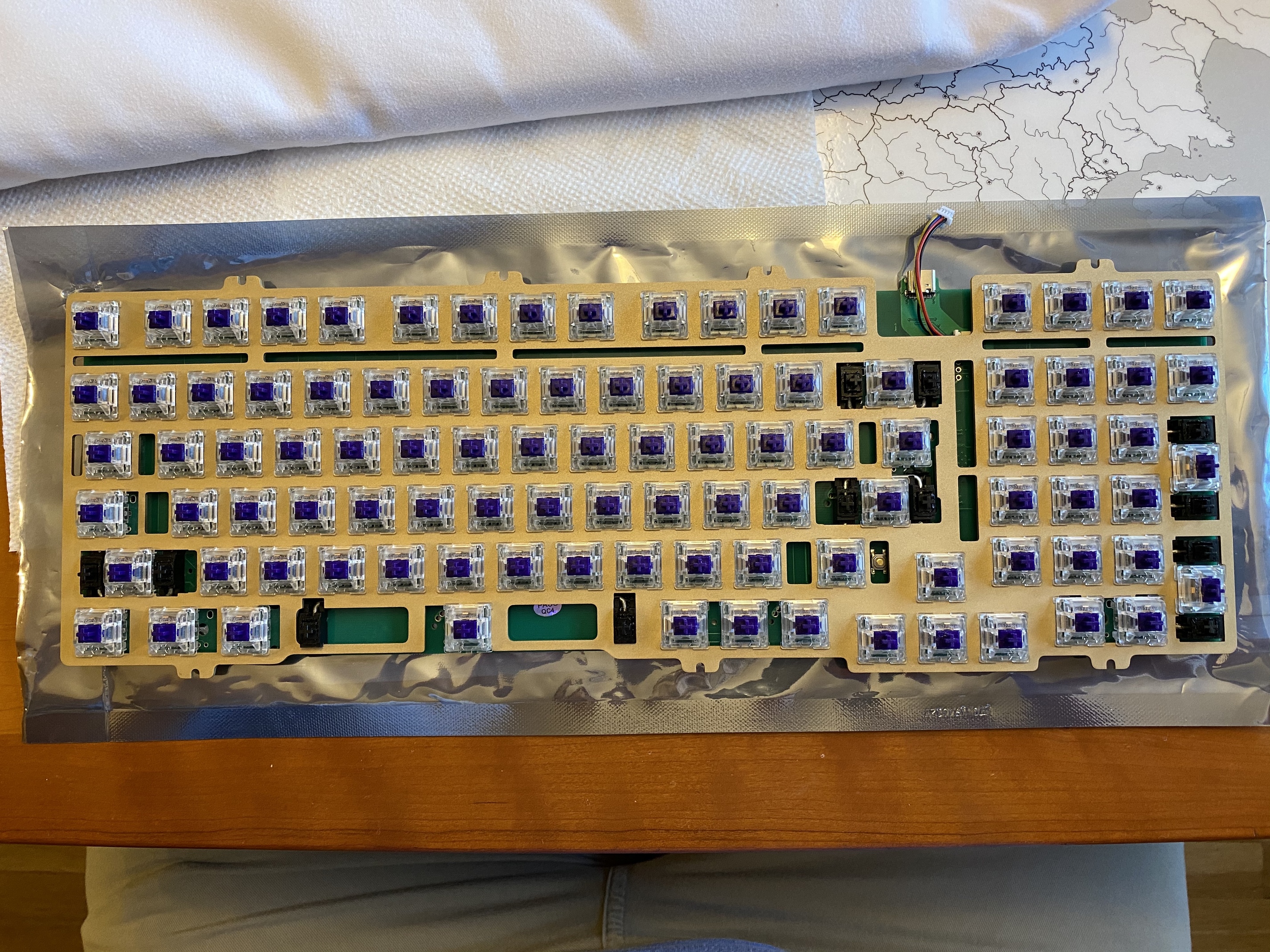
With a nice clean fit between the PCB, the stabs, and the plate, the switches were seated in the plate and PCB, and soldered into place. This is a good time to note another nice feature of the HBCP - the PCB reset button is on the top, and is accessible through a relief cut next to the right shift key. I can’t count the number of times I’ve forgotten to flash a QMK firmware with RESET bound to something I can remember before assembling the keyboard, and it invariably happens on boards where there is no access hole in the case for the reset switch, so it’s nice to know that if I forget again, I can just pop off the right shift key to get to it. Can we please have this feature on every PCB and plate from now on?
And, yeah, it’s some kind of Murphy’s Law for the build - the one time I remember to flash a new hex and put RESET somewhere useful, I didn’t need to bother. Sigh.
Now back to that daughterboard. This is the point in the build where you need to connect the daughterboard to the PCB, and that part’s easy enough if you hold the PCB vertically next to the case top while you insert the connector into the daughterboard socket.
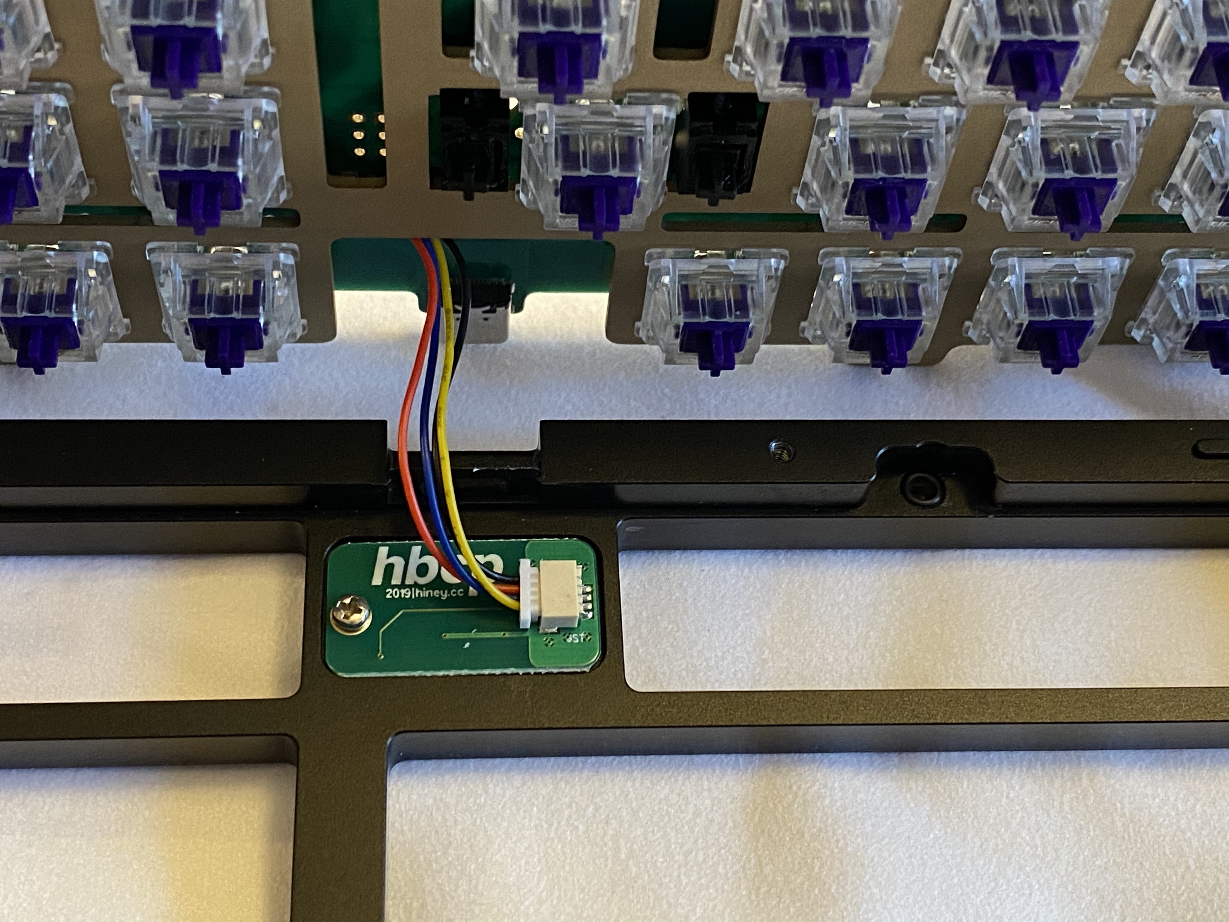
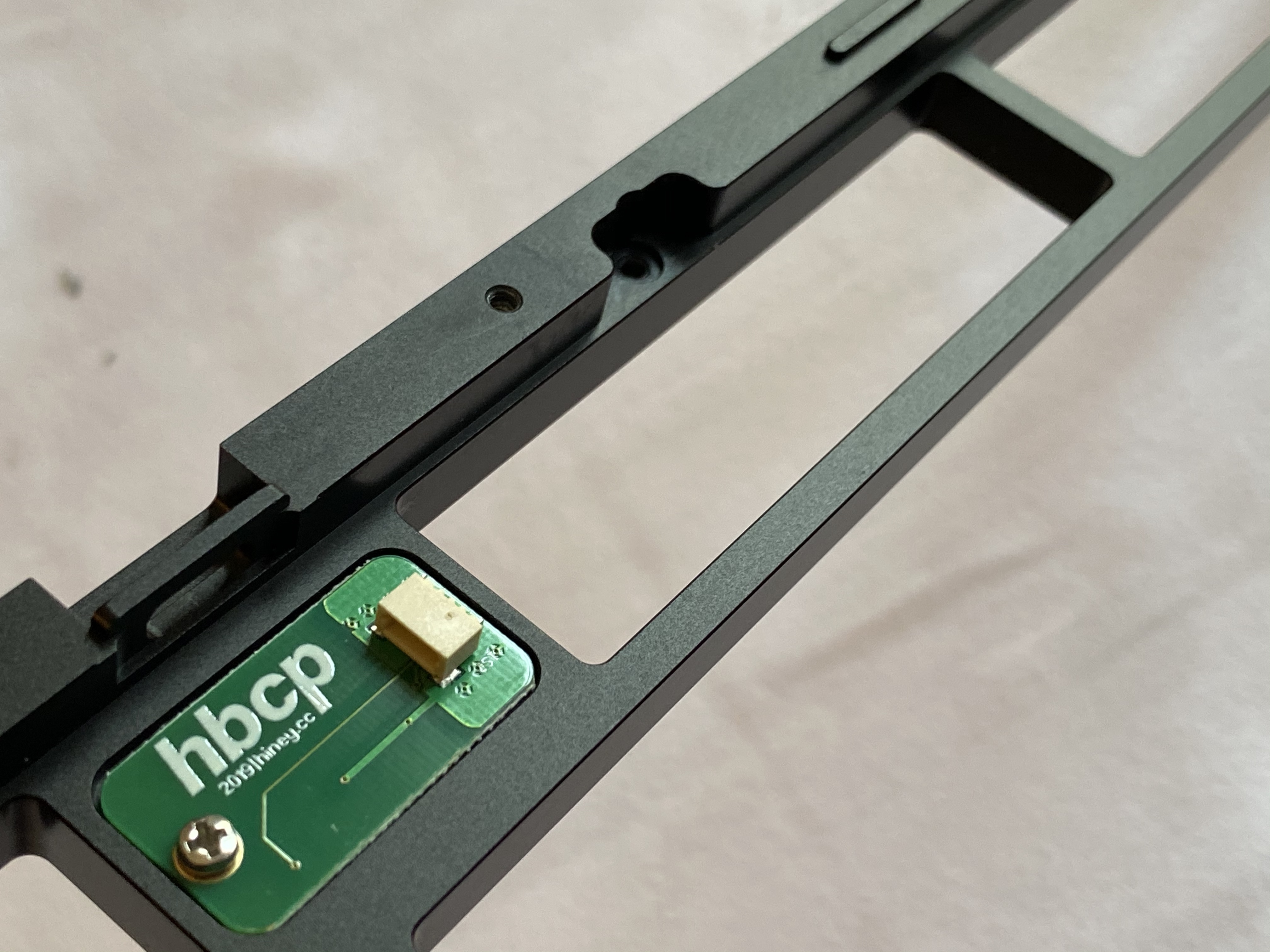
Before we go further, let’s jump back in time a bit, and take a closer look at the positioning of the daughterboard. It’s bounded on one side by the port for the USB-C connector, and, when fully assembled, by switches and keycaps on the other three sides. Also, note the recessed area for the plate screw; the HBCP comes with O-rings, which will sit in those recessed areas for a top-mount setup for the plate.
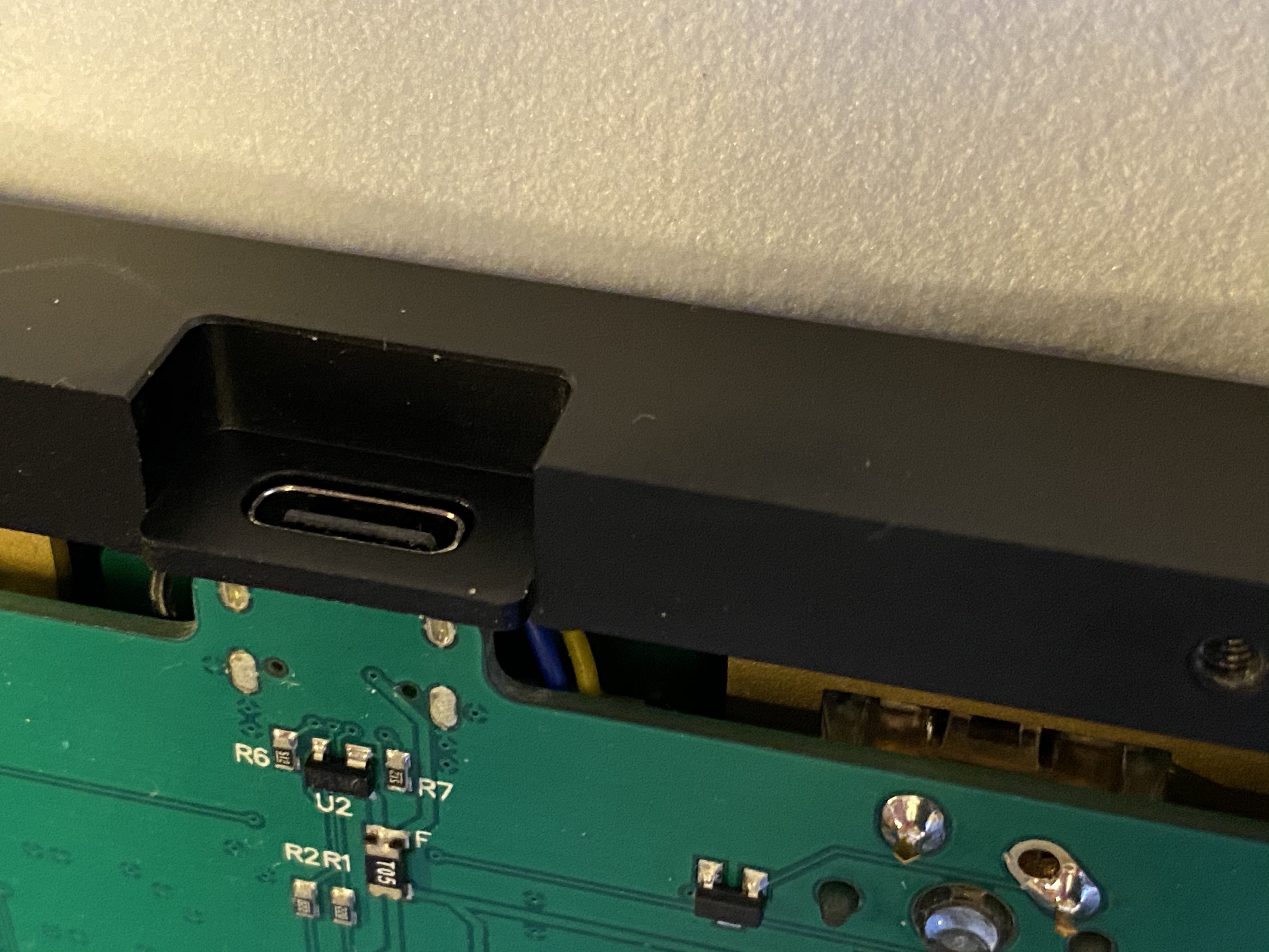
As you may have guessed, things are about to get interesting again. Your mission, should you choose to accept it, is to place O-rings in the recessed screw holes for the plate, and, while screwing in the plate, make sure that the extra connector wiring for the daughterboard is properly tucked into that little bit of space allotted for it. On the first couple of attempts, I found that the wires were getting pinched by the case top when I tried to seat the plate, but it was difficult to position the top to work on it without O-rings falling out of place. Once I realized what the space constraints were, I was able to “bend” the wires to keep them from getting pinched. You can see a couple of them peeking out here, but they’re not being pinched or preventing the plate from seating properly in the case top.
Finally!
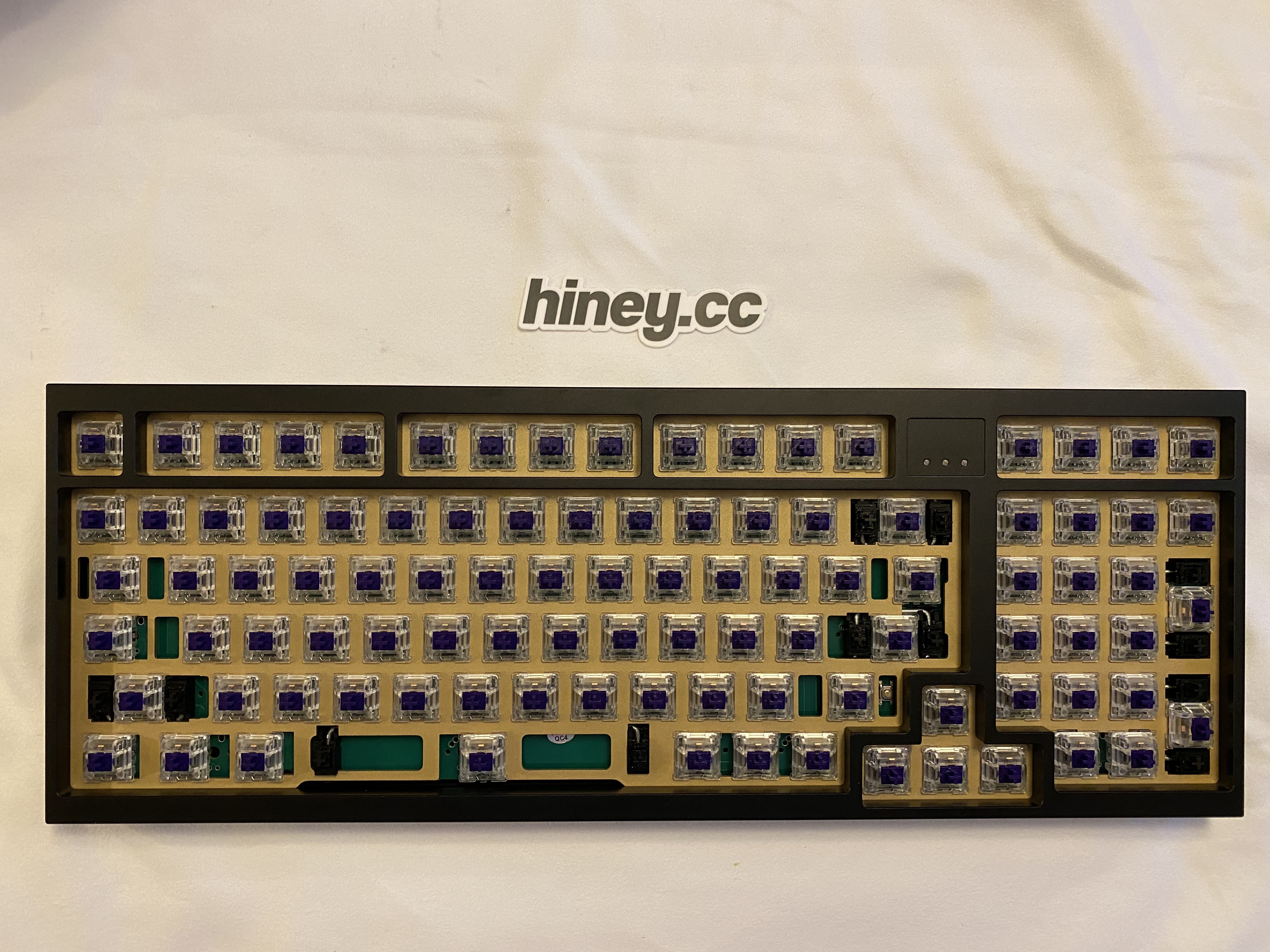
With keycaps, what’s the verdict? This is a heavy boi, with tight clearances between the PCB and the case, and that’s reflected in the sound - deep, bassy, with as much thock as clack. Some of that might be due to the use of 205g0 on the switches instead of my usual 3204, but I think most of it is heft of the board and the O-ring top mount. Part of me wants to try to squeeze a couple more percent of sound improvement out of it with a thin layer of Sorbothane, but honestly, it really doesn’t need it. Sitting on a deskmat, the sound is wonderful.
Lessons learned
- Patience! Between trace cutting, stab filing, and wire placement, this build had a few more challenges than the usual slap-it-together-60, but none of these are big issues - just take your time.
- Every GB has its own twists and turns, and you always end up in a slightly different place than you imagined when you started. This was my first keyboard GB with Hiney, and hopefully not the last; progress communication during the GB, and support for issues after the GB, was A+.
- I need to remember the stab filing trick - I’ve gone with plate filing in the past to address cutout issues, but this was easier (and if I screw it up on some future build, it’s cheaper to replace a stab than a plate!)
- I tried 205g0 on tactiles for the first time (I’ve used it on linears before). As always with 205g0, you have to be careful to apply a thin coat, but you can get an even more buttery feel than 3204, if that’s your thing.
- Do I really understand the variables in board sound? Every time I think I’ve started to get a handle on it, a board comes along and messes with me. This board sounds significantly better than my expectations (which were relatively high to begin with, thanks to build videos like this one), and despite my commentary earlier, I’m not entirely sure I understand why.
But I’m not complaining. Welcome to the rotation!
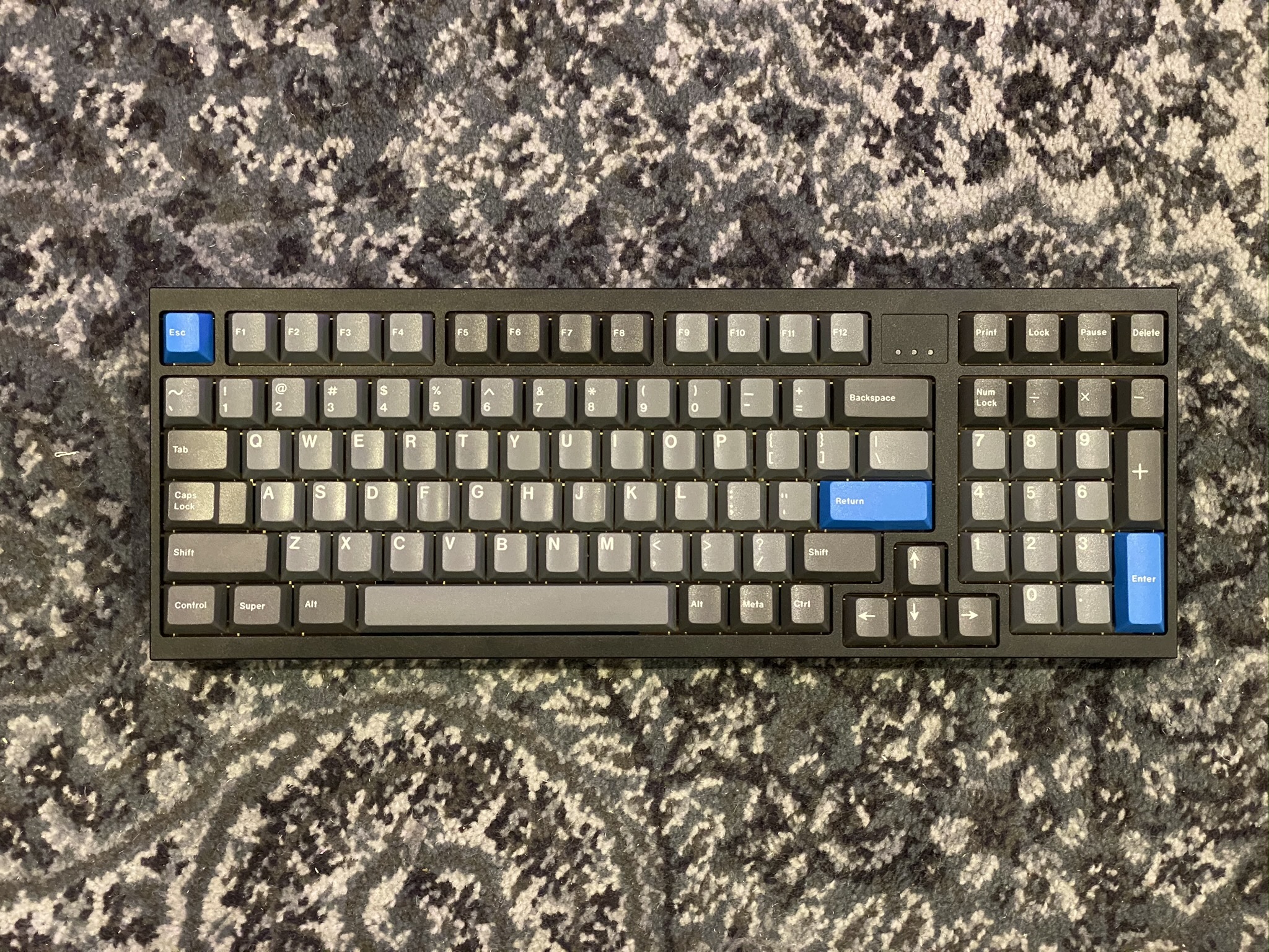
The HBCP looks like this in real life.
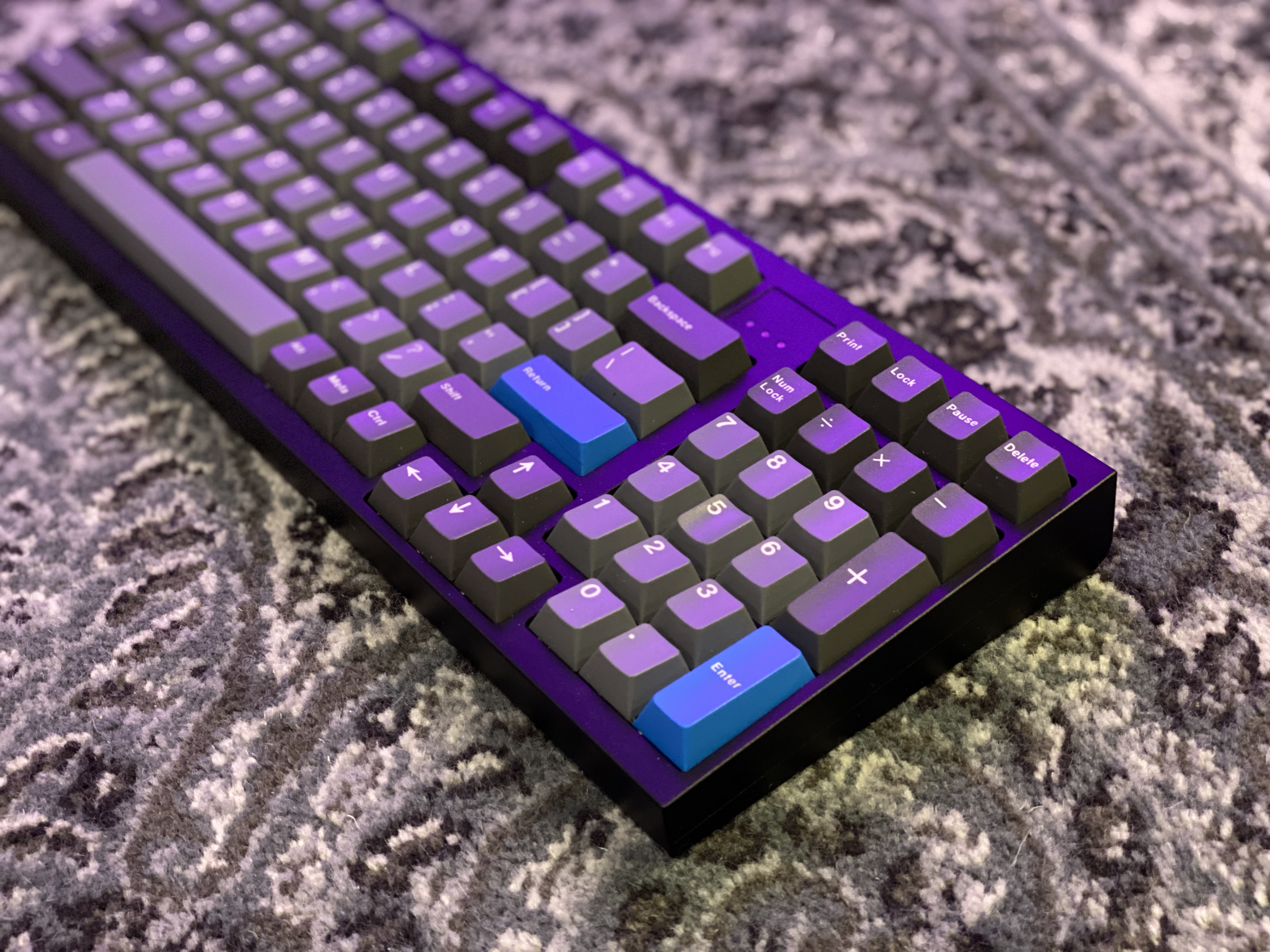
The HBCP doesn’t look like this in real life, unless I leave my Hue lights set to purple. But maybe I should.
Specifications
case: Hineybush HBCP
- black anodized aluminum
case dampening: top-mount O-rings
PCB: Hineybush HBCP (AT90USB1286)
plate: matte finish brass
plate/PCB dampening: n/a (relief cuts)
stabilizers: GMK PCB screw-in
- 1x6.25u, 5x2u
stabilizer mods:
- clipped and lubed with SuperLube
- HBCP stab spacers on screws/tabs
- left spacebar stab filed for 6.25u plate fit
switches: 98x 78g V2 Zealios
switch mods:
- springs tub-lubed with Krytox GPL 104
- stems hand-lubed with Krytox GPL 205g0
- no housing lube
keycaps: GMK Oblivion V2
- monochrome base
HxWxD (without caps or feet): 1.19" x 14.94" x 5.44"
HxWxD (without caps): 1.25" x 14.94" x 5.44"
HxWxD: 1.5" x 14.94" x 5.44"
assembled weight: 3.07 kg (6.76 lb)