Build #17: TX108se
As even relatively new members to the community can quickly ascertain, most of the action in the custom mechanical keyboard world takes place in the 60/65/75/TKL space, with the occasional foray into 1800-land. And there are good reasons for that - sacrificing unused blocks of keys is a good way to reclaim desk space, whether for reasons of aesthetics, ergonomics, or some combination of the two.
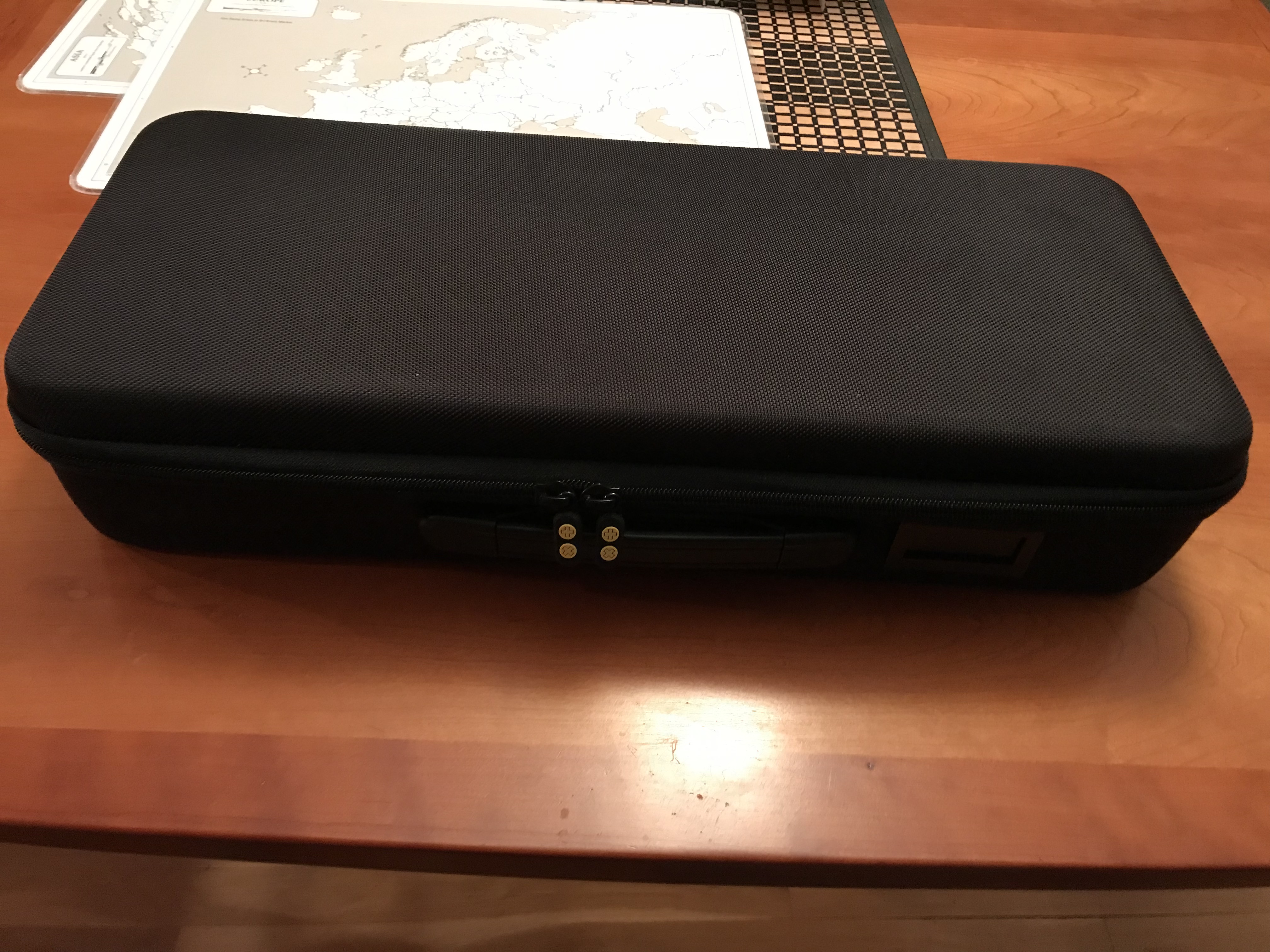
Sometimes, however, you just gotta go big. To find out for ourselves whether size matters, I decided to take a run at the tx108se, a full-size design from Kin of TX Keyboards. Before we get into the build, a quick look at the case, which seems well-constructed and durable - a good thing, given the hefty monster inside.
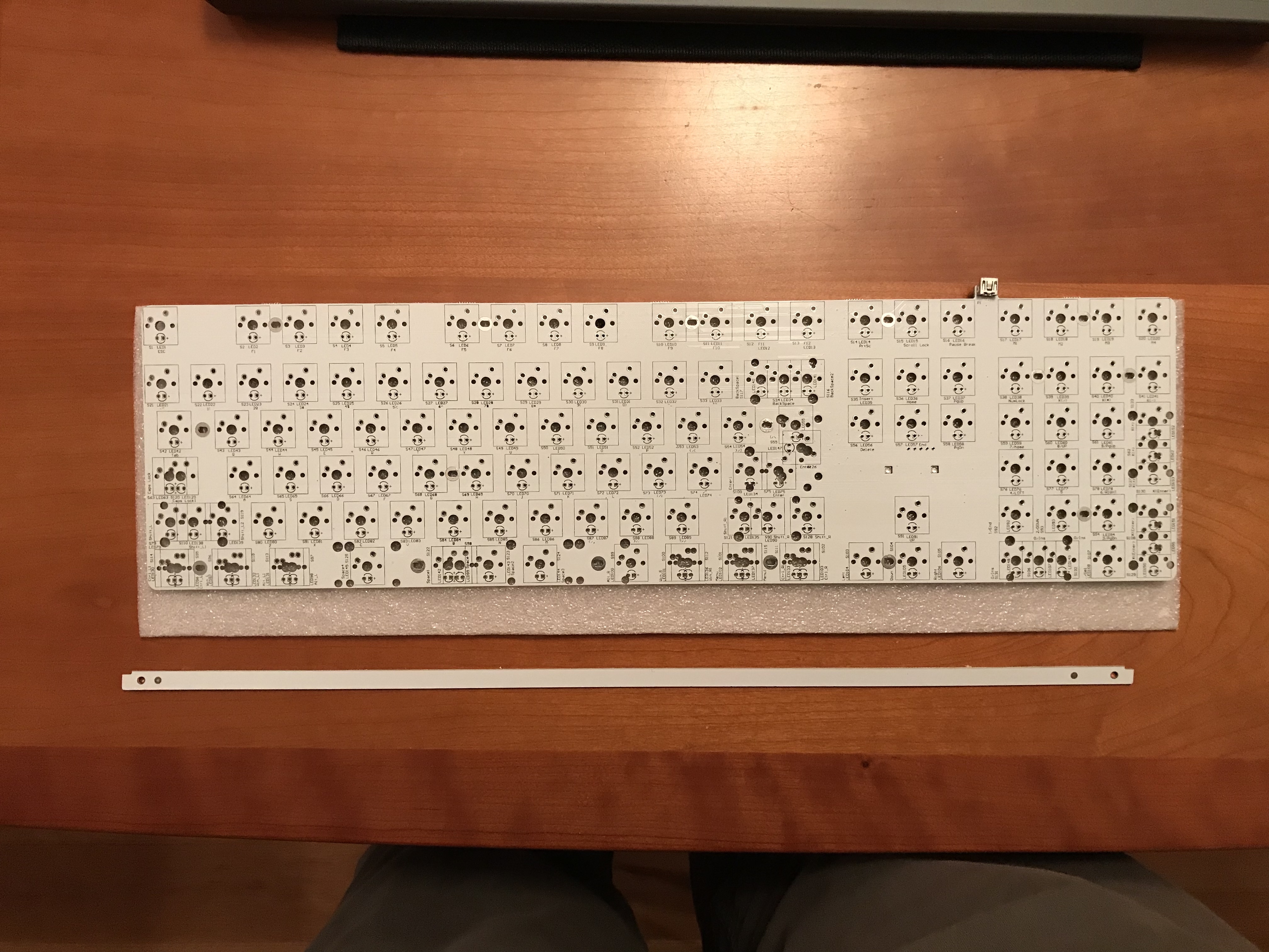
The first thing we’ll have to contend with is the PCB. As shipped, it has two extra strips of material attached to the top and bottom of the PCB. The top one effectively blocks the USB connector, which is your clue that it’s meant to be removed. I neglected to get a shot of the PCB with both strips attached, but here’s a look at the PCB with the bottom strip intact.

That seam doesn’t look like it’s cut deeply enough to permit the strip to snap off, and it doesn’t feel like it, either. But with enough force on the ends, it can be pried off manually, and once it’s begun to break away, removing the remainder of the strip becomes easier.
Once that was done, I tested the PCB (and a spare) with tweezers to make sure they were working.
Things I like about this PCB: clear labeling of all keys, LED polarities, and switch placements.
Granted, switch and stab placement aren’t exactly ambiguous on a full-size layout, but it’s still
nice.
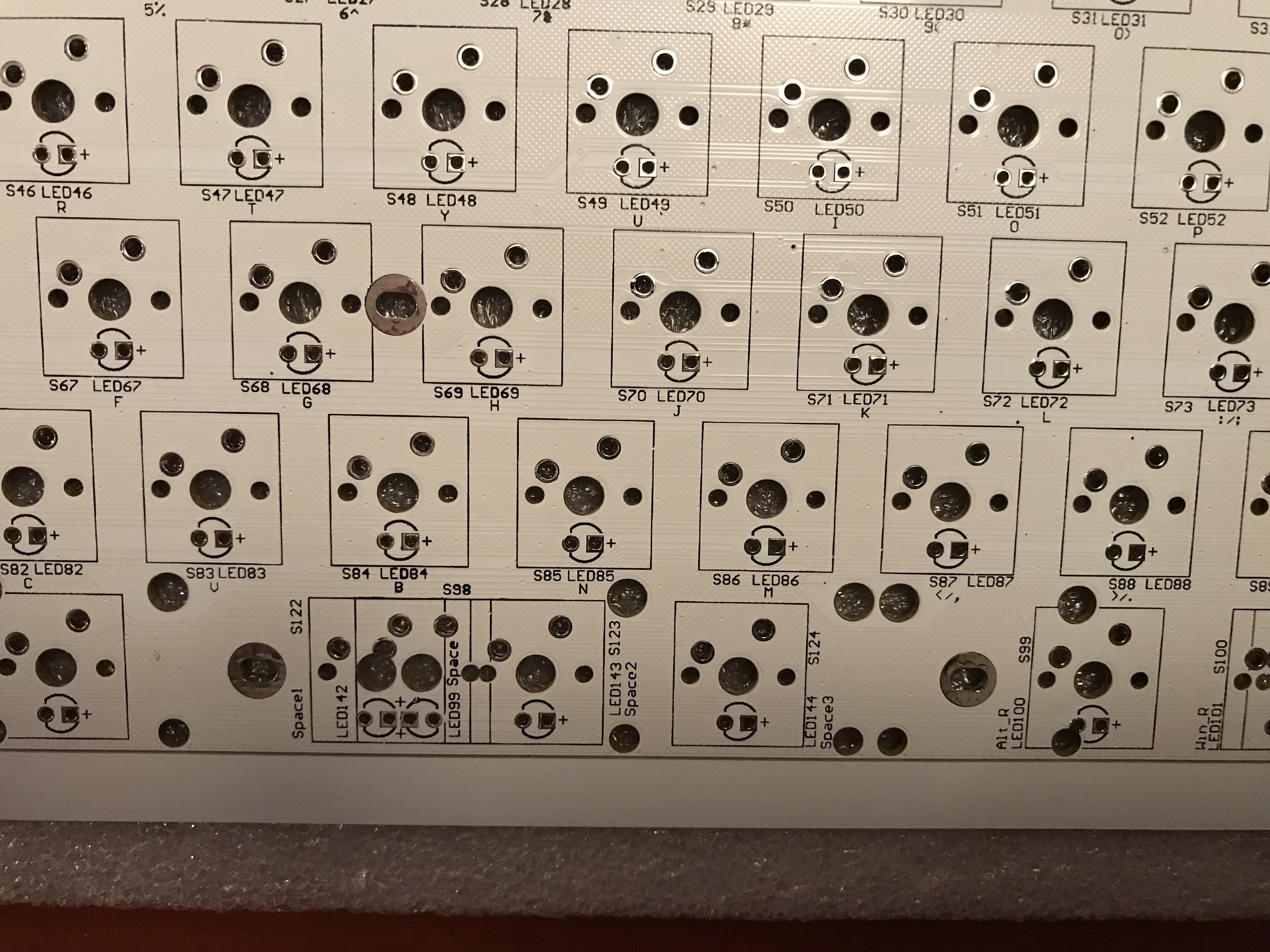
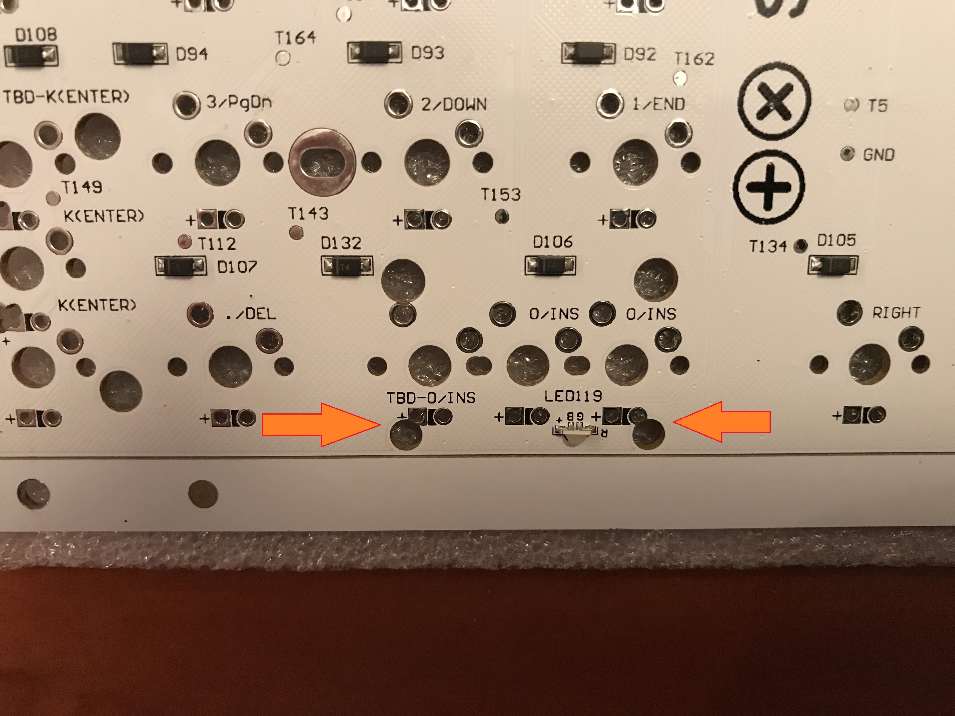
Things I don’t like: we’re going to have to be careful with the GMK screw-in stabilizers to make sure we don’t short anything out with the screws. Take a look at the overlapping screw holes and pads.
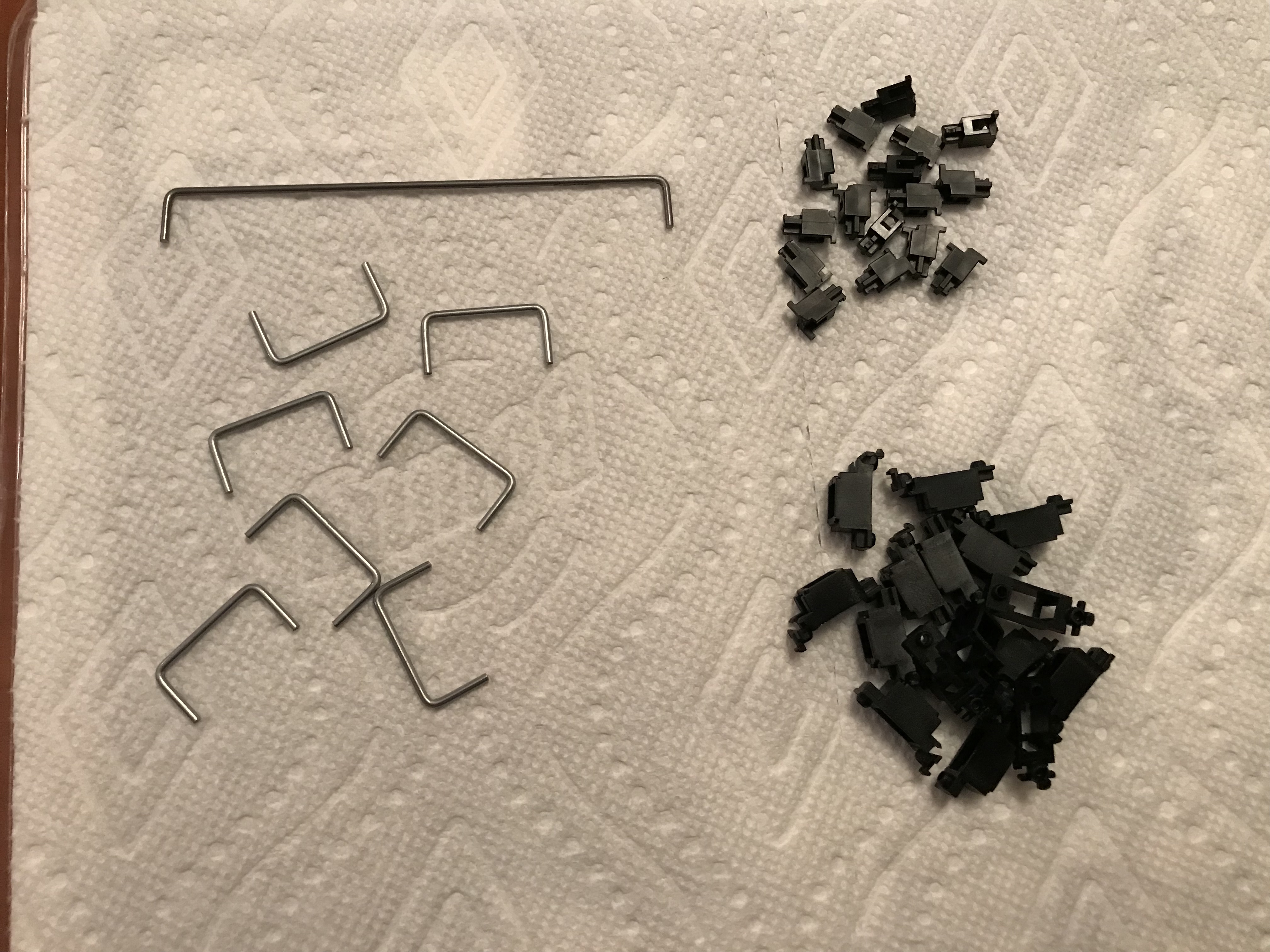
This board actually supports a number of split layouts, to the degree that if I had opted to split backspace, both shifts, the spacebar, and the three 2u numpad keys, I would have needed only 3x2u stabs, for left and right space and enter. But in the end, I decided to keep things conventional, and so I needed 1x6.25u and 7x2u stabs. Here, I’ve just finished disassembling and clipping the stabs:
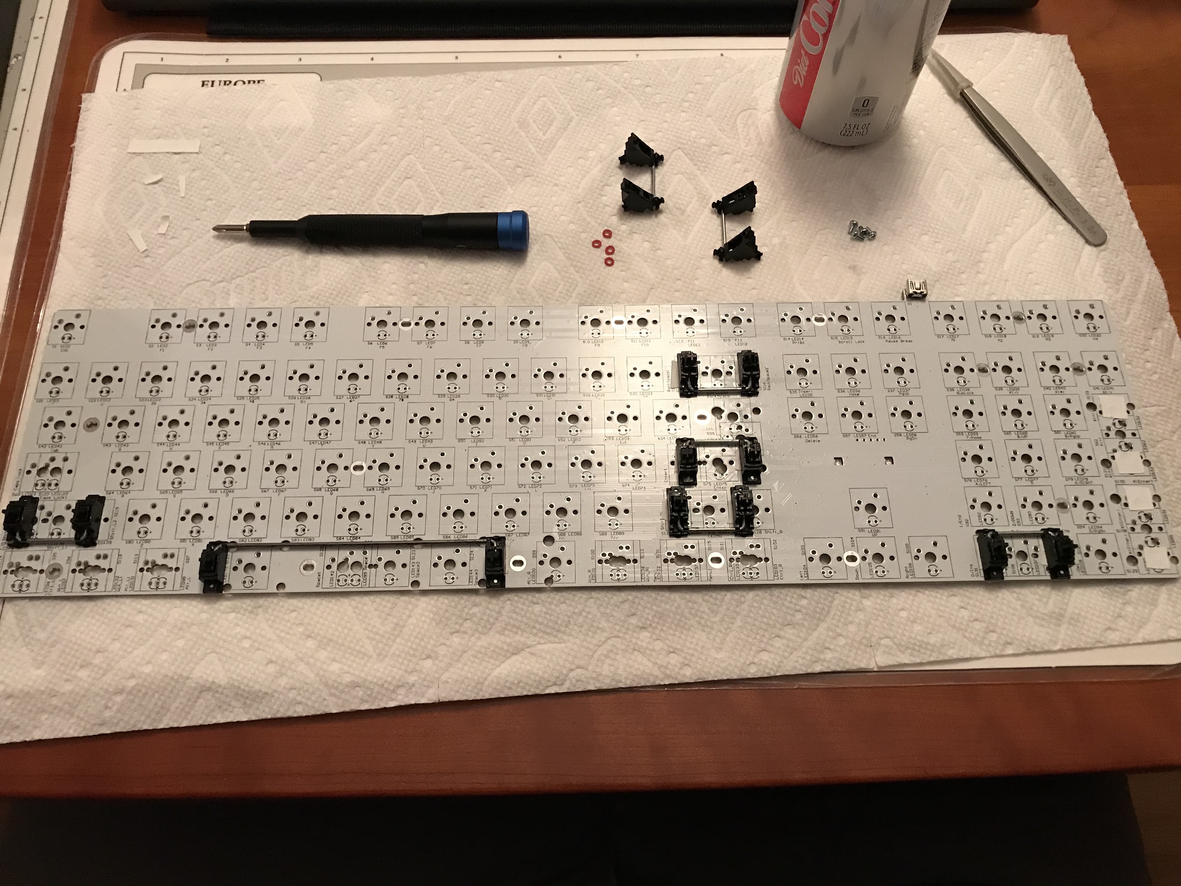
After lubing the stabs, here’s a look midway through installation. Looking at the numpad, we see white gaffer tape for the bandaid mod, and, above the PCB, the remaining stabs, screws, and the washers I use to prevent any possibility of shorts with the screws.
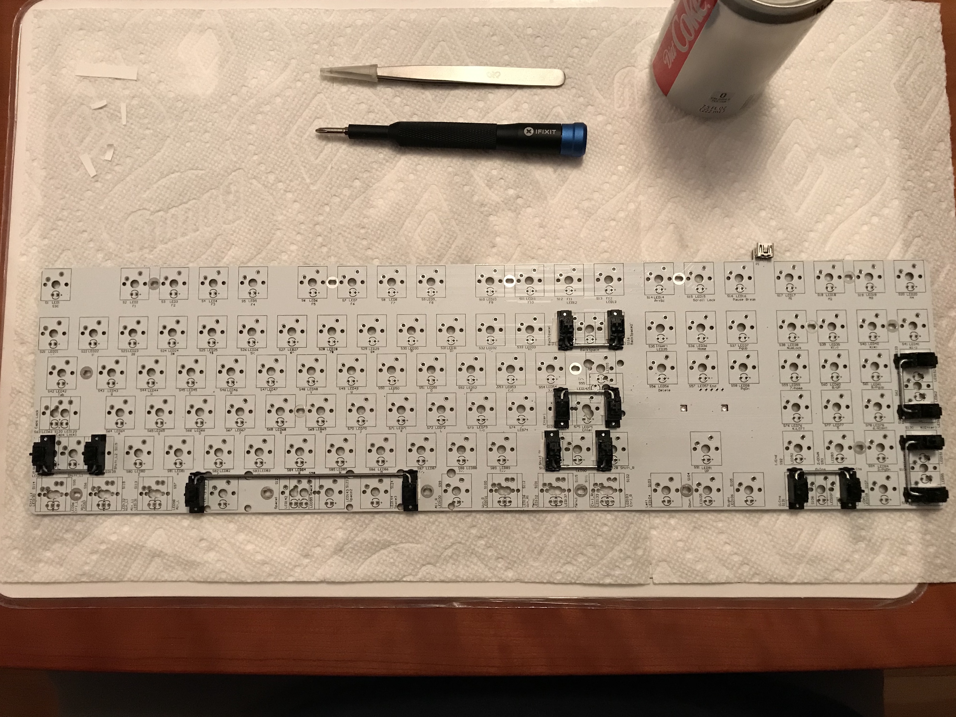
All done with the stabs.
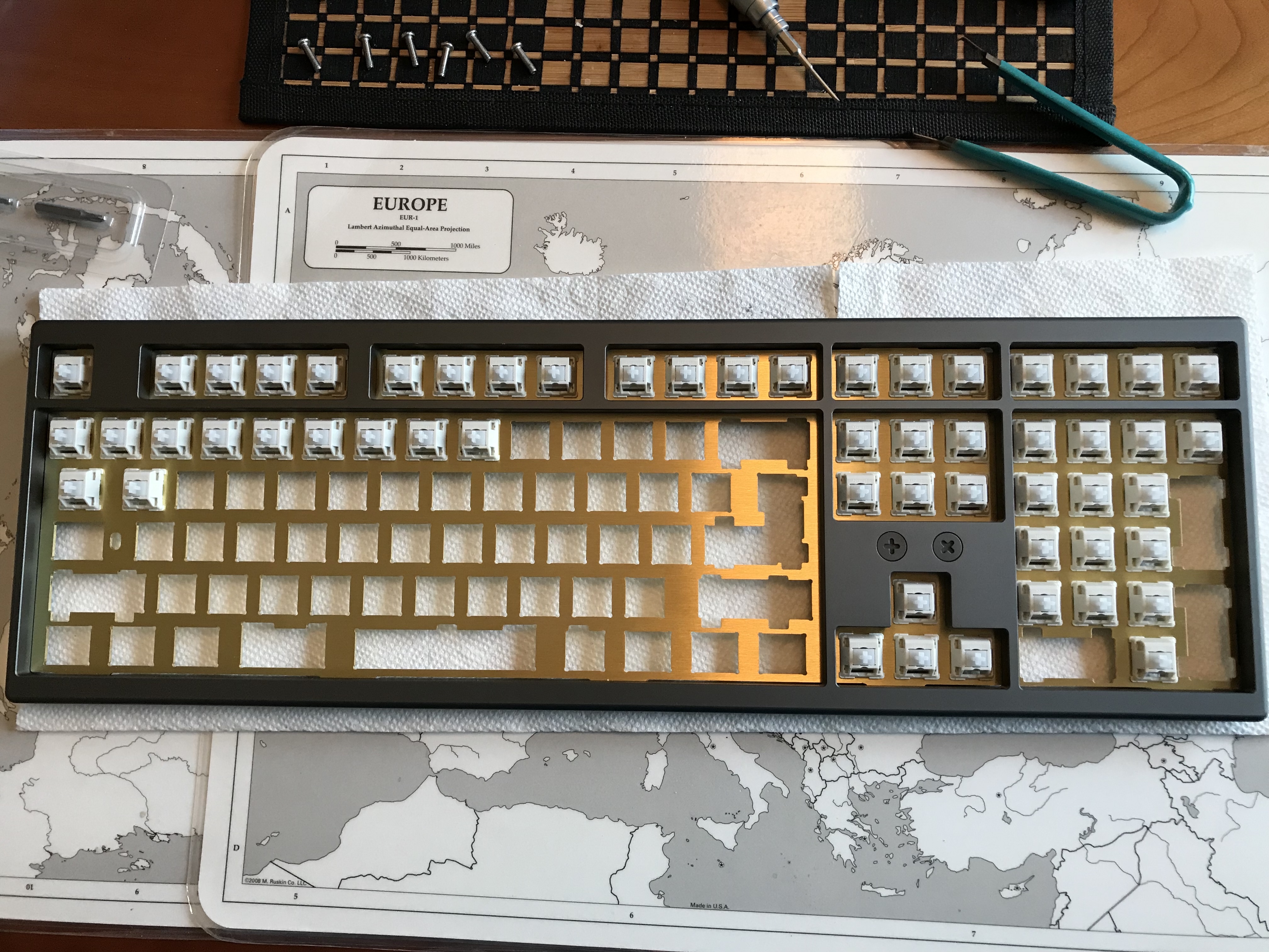
Here’s the first look at the top of the tx108se case. The anodization is very nice, as is the finish on the brass plate. Less nice from a build perspective - the tight fit for switches, exacerbated here by the choice of Holy GSUS switches. I got about this far pressing switches into the plate before my thumbs demanded a break. Painful. To finish placing the switches, I ended up folding a paper towel into a thick square and using that to distribute the force a bit more evenly on my thumb.
A look at the reverse side of the case top, showing the screw mounts for the plate, as well as the 12 screw holes for joining the case halves.

With all of that brass, and the use of heavily tactile switches, we can expect significant ping, so it’s time to address acoustics. Before soldering, I placed a few strips of 4mm-thick Sorbothane on the plate, to be sandwiched between the plate and the PCB.
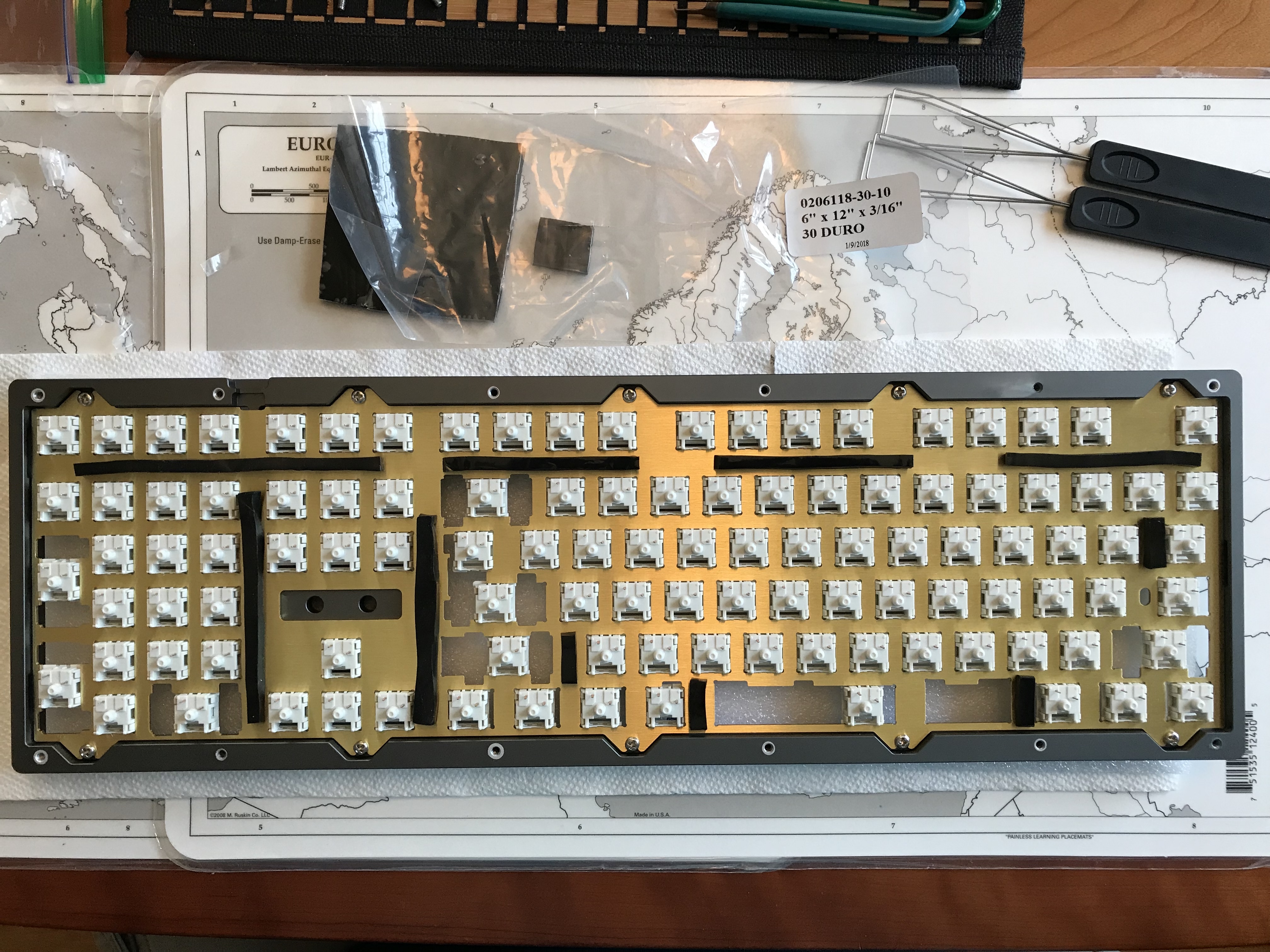
Normally, I wouldn’t seat all of the switches in the plate before soldering even a single switch into the PCB. However, two factors pushed me in this direction. First, the extremely tight fit of the switches in the plate, and the level of force needed to properly seat them, made me think it might be safer to fit the switches first to avoid any potential damage to the PCB. Second, a quick test of fit led me to believe that it wouldn’t be hard to drop the PCB into position (the absence of PCB mounting pins on the GSUS housings helps as well).
Because the gap between a 1.5mm plate and the PCB for an MX build is nominally 3.5mm, the 4mm Sorbothane will compress a little bit when the PCB is properly in place. With the Sorbothane placed on the plate before soldering, this can make it difficult to ensure that the switches are seated properly and making good contact with the PCB, since the Sorbothane compression is pushing the other way. It helps here to have a child willing to apply pressure while soldering takes place, although C-clamps would presumably be a much more cost-effective solution than having a child. Your call.
With the soldering done, more Sorbothane is laid in place on the PCB. There’s no particular reason for the gap between the sheets - I had two pieces of about the right size, and used them with the plastic backing left in place.
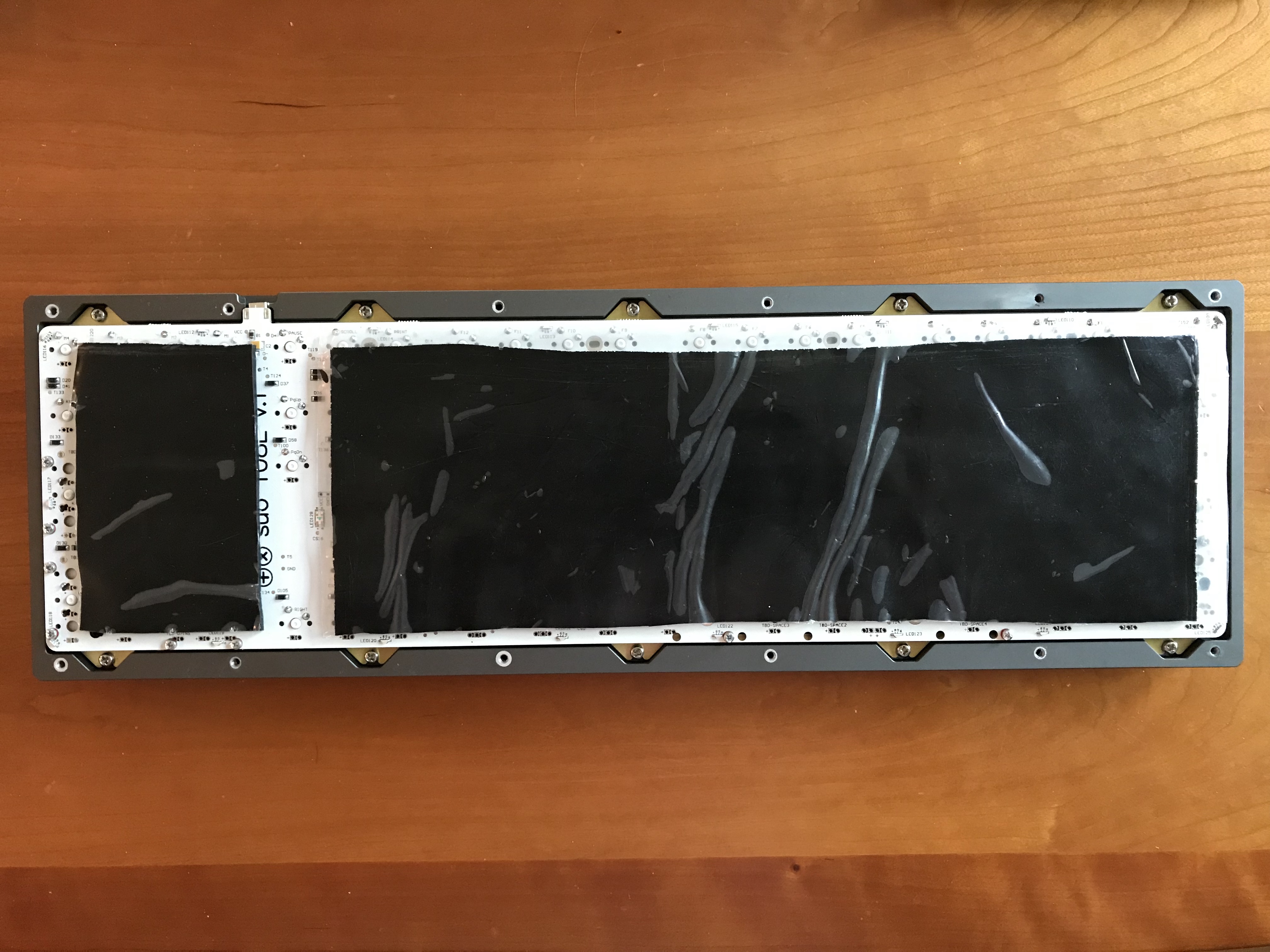
There is a polycarbonate diffuser for the RGB backlighting, which is sandwiched between the top and bottom pieces of the case and held in place by the case screws.
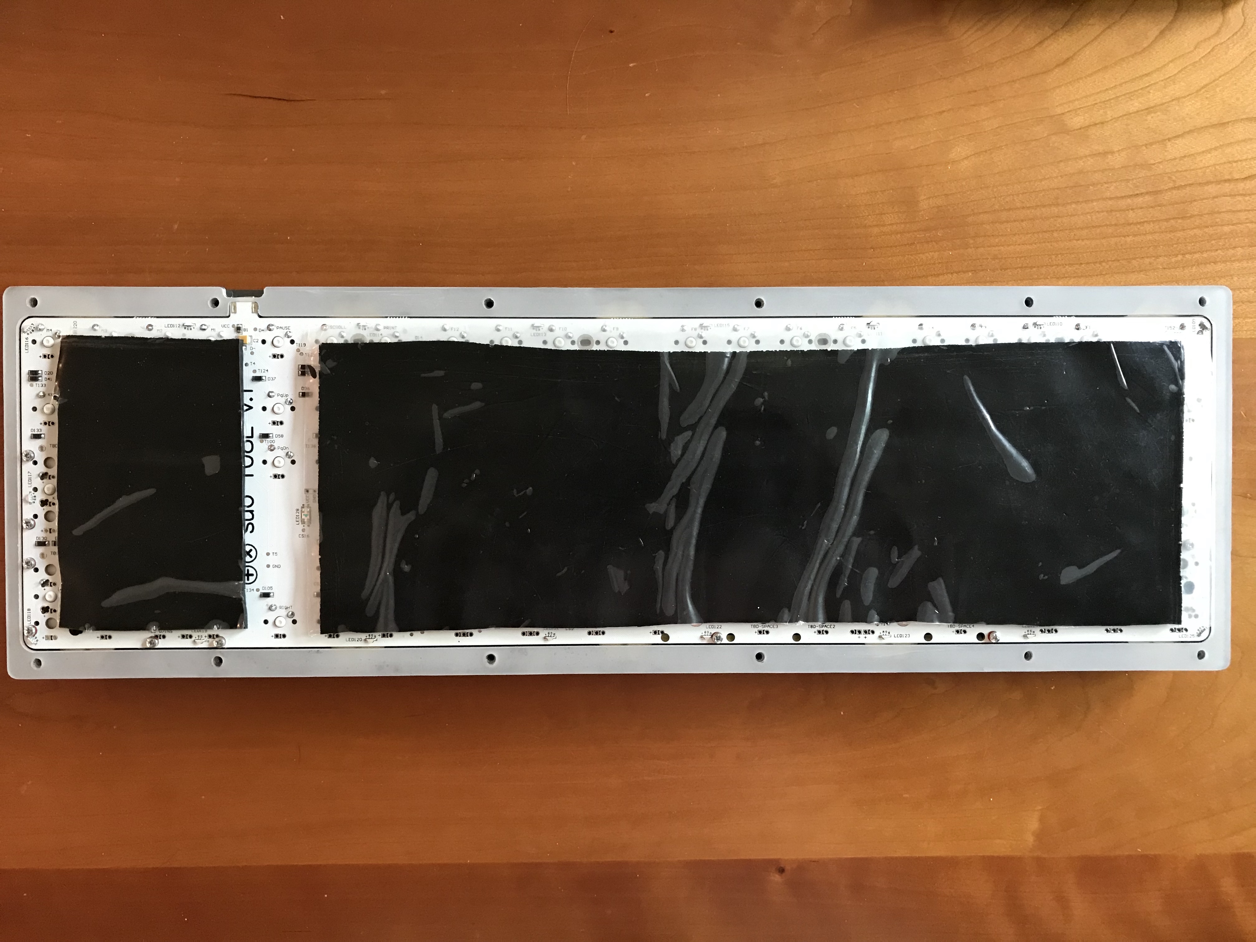
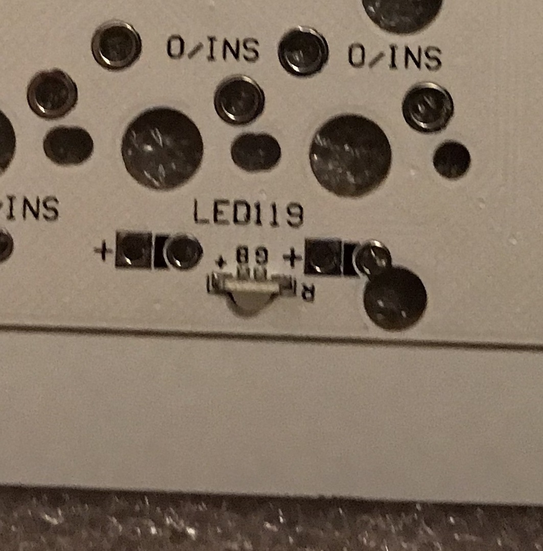
In case you’re wondering, the Sorbothane sheets do not block the RGB backlighting. The LEDs are triangular, mounted on the perimeter of the PCB, and illuminate directly outward. Here’s a close-up of one such LED, before the extra strip of material was snapped off of the PCB:
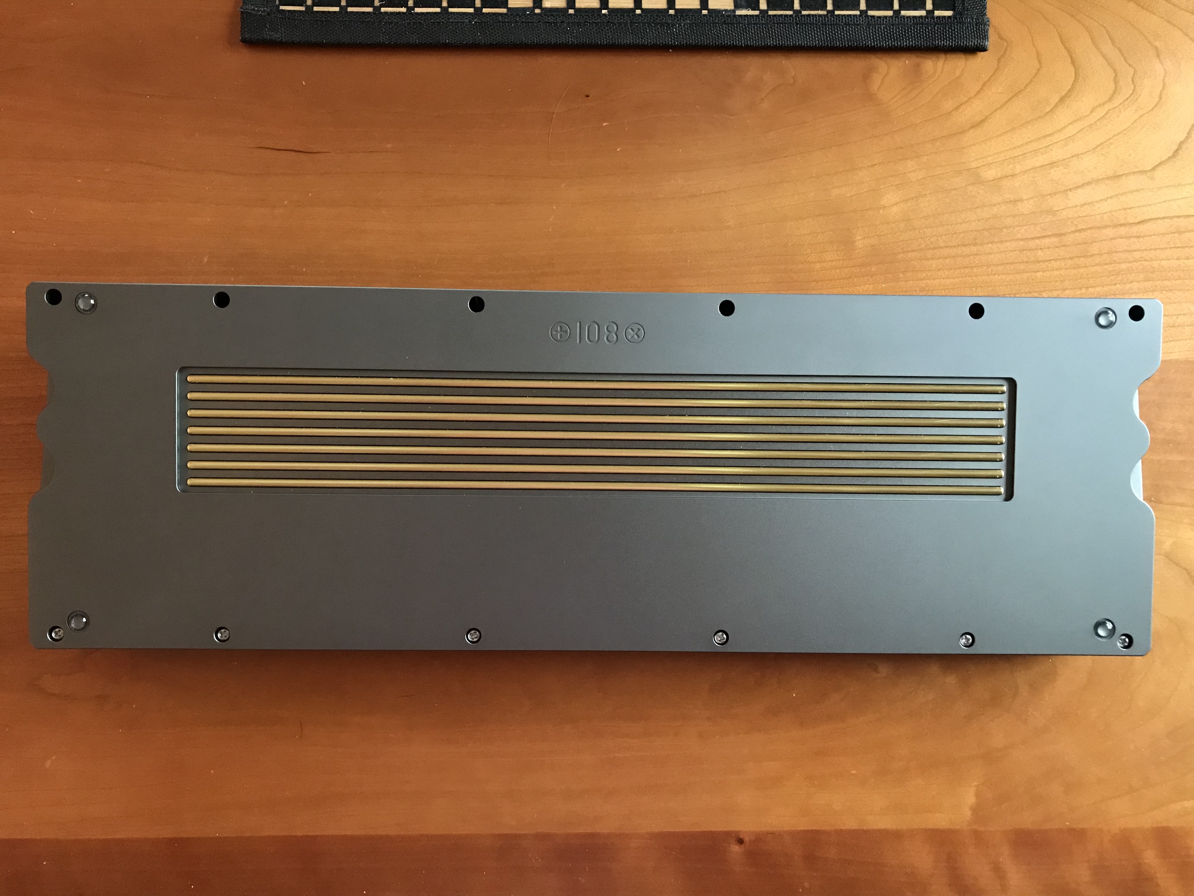
Big boi’s got back. I have to be honest; this is my least favorite part of the design. I’m not convinced by the grill work, nor by the color/texture combination of shiny brass and matte grey. On the other hand, the anodization is really good. This photo does not do it justice.
I note in passing that getting this screwed back together was a bit more work than I anticipated; the tolerances on the screw holes and screws were very tight, to the point that certain combinations of screws and screw holes would not work. I ended up playing whack-a-mole with the screws to figure out which ones would actually seat properly in each hole.
I particularly enjoy the new feature I’m pioneering with this board, which I call “top-mounted RGB”.
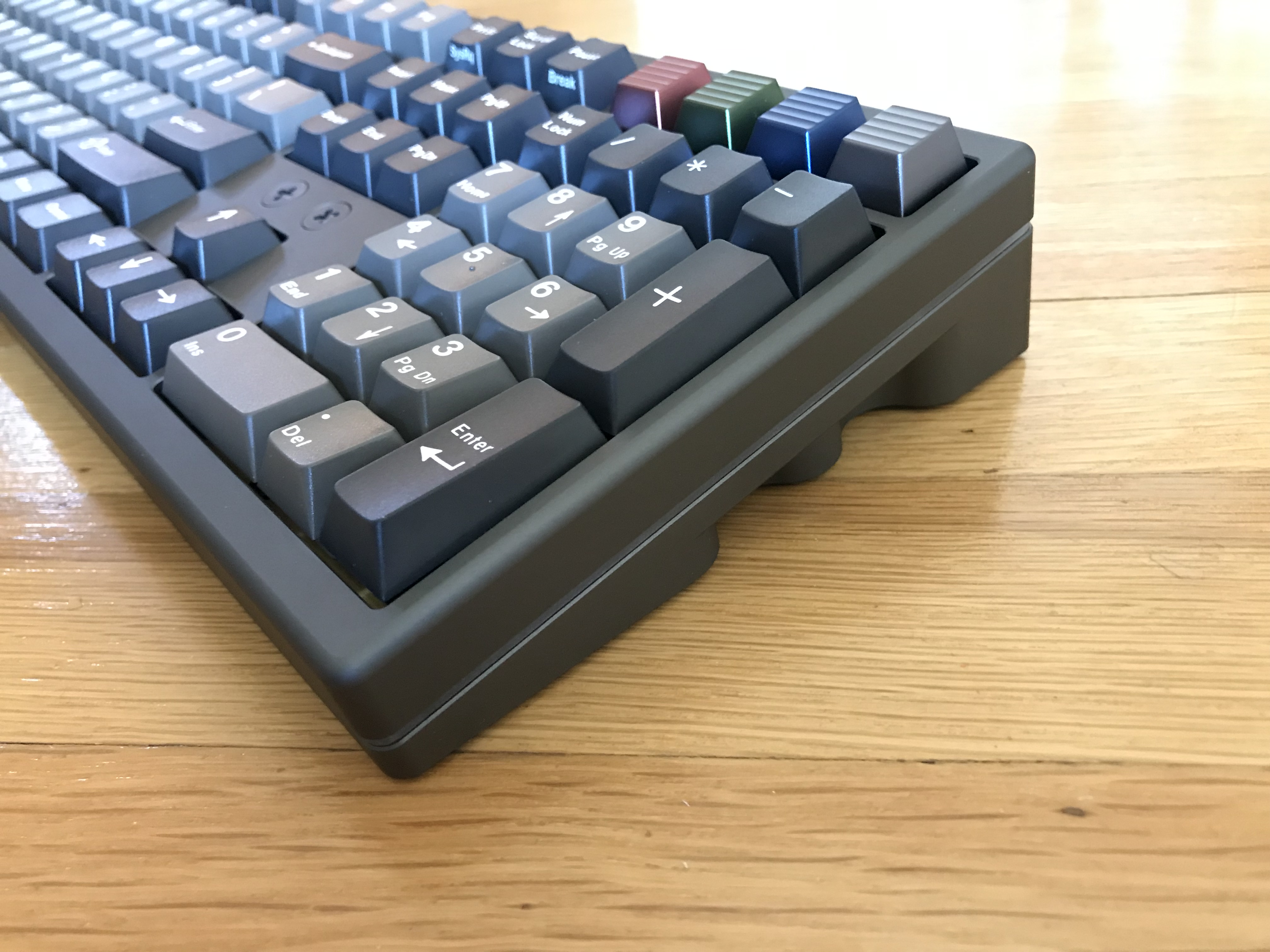
I kid, I kid. While we’re here, have a gander at the side view of the controversial new design feature Kin has introduced on the latest round of the TX lineup, the curved notches on the board sides. While I get that it’s a big change stylistically from previous rounds, and may not be everyone’s cup of tea, I will say this: I’m happy those finger grips are there when I have to move this beast.
With this board, Kin has moved away from Jigon to a new custom tool, but it is definitely a work in progress; I’ve been able to control lighting with it, but so far I’ve had zero luck configuring the keys. The good news, I suppose, is that the PCB came with all keys in a reasonable default configuration. At some point, I’m thinking of porting this to QMK with a spare suo108 PCB, but that’s a longer-term goal.
Lessons learned
- It’s one of those little steps that’s easy to forget - be sure to check the stab holes for overlaps with pads, and in the event of overlap, place non-conductive washers to guard against shorts with screw-mount stabs.
- Unfortunately, this build was completed before @donpark shared his approach for placing Sorbothane between the PCB and plate. I’ve since tried that approach; it works well, and it’s the way I will likely approach the mod going forward.
- All of the sound dampening does a great job eliminating plate and case ping. With that said, this is still a loud boi, particularly the spacebar. Not unexpected, since I chose loud switches, but still.
- This build was literally painful - bruised my thumbs getting all of the switches into that plate. It’s probably worth investing in a pair of heavy-duty work gloves if and when I have to deal with another plate like this.
- Keep track of screw locations during disassembly, when the tolerances are as tight as they are on this board. It will be easier to reassemble if you put the screws in the same holes from which they were removed.
- I generally associate increased heft with increased potential for improved acoustics, but somewhere between 5 and 9 pounds, increased heft is just increased heft.
- The hype on TX finish and tolerances seems to be justified. Very smooth ano, and very clean seams.
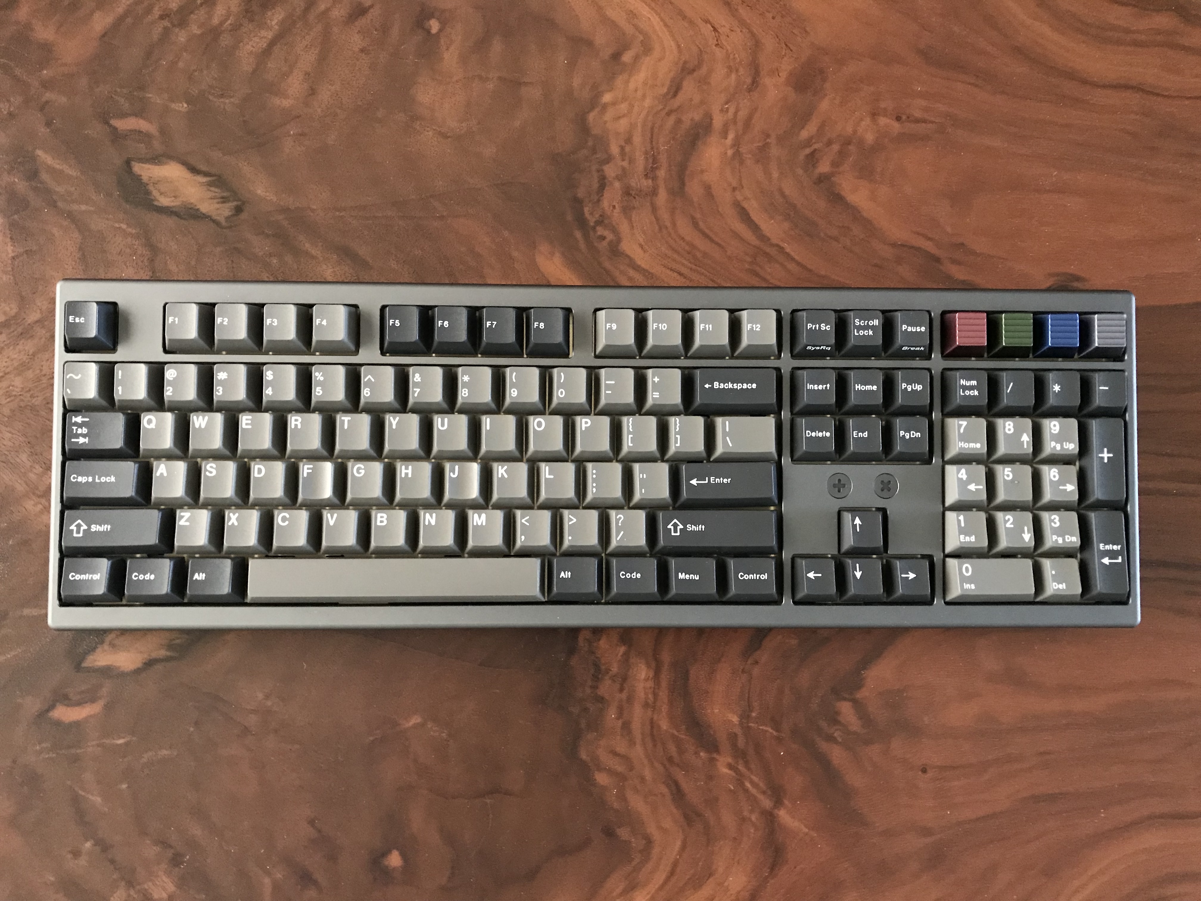
Let’s wrap this up with another object lesson in lighting and color. GMK Dolch, particularly on this board, is a chameleon. Indoors, under incandescent lighting:
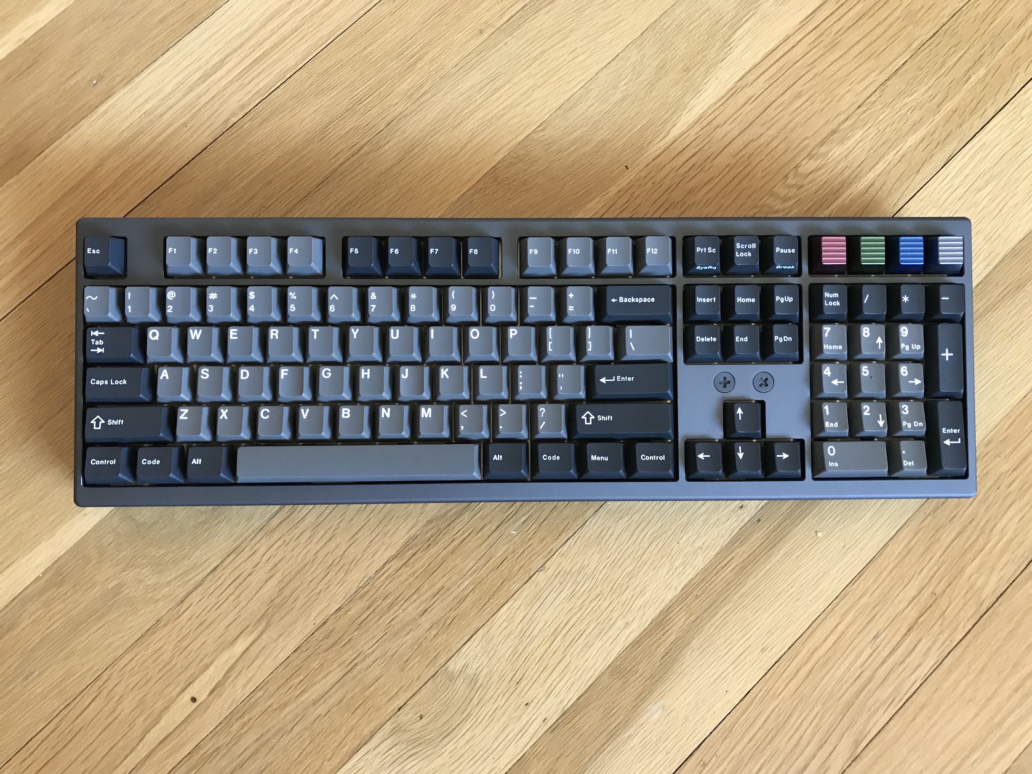
Indoors, under natural daylight through the window. A chameleon. An attractively plump 9.97-pound chameleon.
Specifications
case: TX108se anodized aluminum (grey)
case dampening: 0.1" 30 Duro Sorbothane sheets
PCB: suo108
plate: 1.5mm brass
LEDs: RGB underglow built into PCB
switches: Holy GSUS
- Bsun GSUS housing & springs
- Halo Clear stems
switch lubing:
- manually lubed housings/stems with Tribosys 3204
- tub lubed springs with Krytox GPL 104
keycaps:
- GMK Dolch
- 4x Rama Wave SEQ2 AL
stabilizers: GMK screw-in
stabilizer mods: clipped, lubed with SuperLube,
  bandaid-style mod with gaffer tape
plate/PCB dampening: 0.25" 50 Duro Sorbothane, ~4mm wide strips
HxWxD (without feet or caps): 1.63"x17.31"x5.63"
HxWxD (without caps): 1.69"x17.31"x5.63"
HxWxD: 2.0"x17.31"x5.63"
assembled weight: 9.97 lbs