So I’ve been thinking about ways to make reasonably-precise key switch force-displacement curves for those of us who aren’t as courageous as @haata when it comes to buying used industrial equipment on eBay.
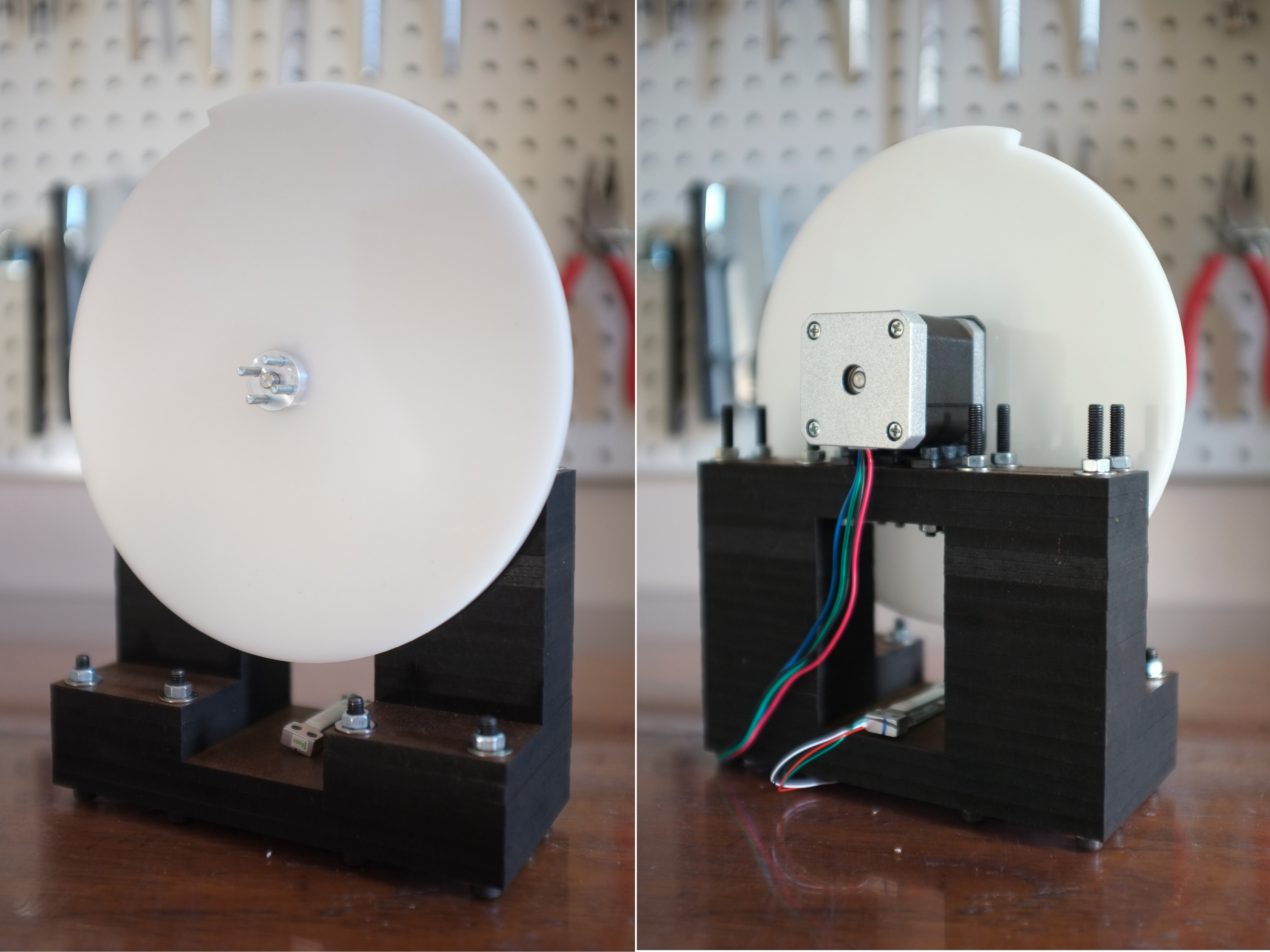
After iterating through a bunch of overly-complicated designs involving lead screws and timing belts I settled on what I hope will be an elegant solution - a modestly-spiralled “displacement disc” with a uniformly-increasing radius. It’s attached directly to a 400 step/revolution stepper motor and widens by 5mm across the full revolution, for a displacement resolution of 0.0125 mm/step.
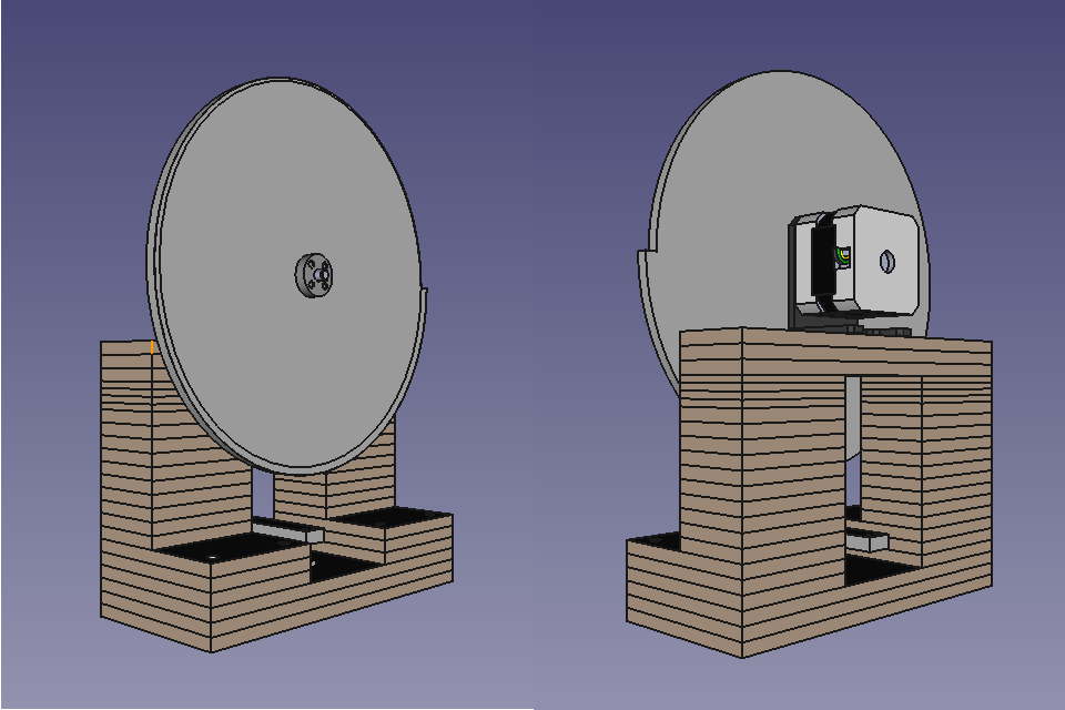
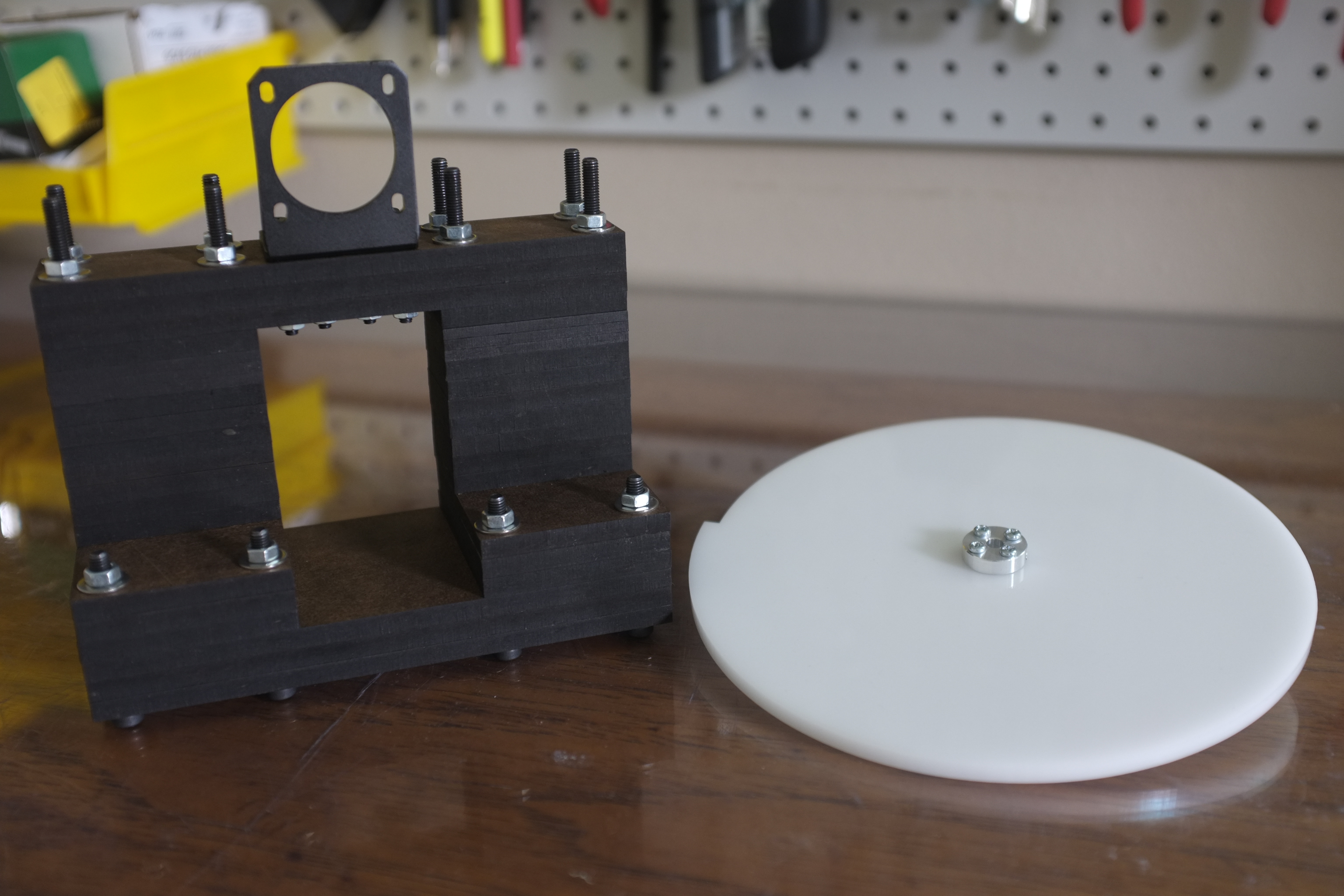
The stepper motor and disc are supported by layers of laser cut 5mm hardbard, with some 3mm spacers thrown in to allow for mixing and matching spacer thicknesses to acheive a desired motor mount height. I still have some work to do on designing the load cell mount (in the CAD renders above it’s just floating in space) and hot-swapping keyswitches. I have a good idea of what to do for the former, whereas I need to think about the latter a bit more (suggestions welcomed!).
I figured I would go ahead and see how the displacement disc and frame worked for now - I received the cutouts from Ponoko yesterday and was pleasantly surprised to find that everything fit together nicely on the first design iteration (good job FreeCAD and Inkscape):

The stepper motor should come in early next week at which point I’ll be able to mount the disc to the frame. I’ll get the load cell at the same time and will start thinking about a switch-mounting design. Assuming I can figure that out, the last step will be plugging everything into an Arduino and writing the measurement software. I also intend to measure switch actuation and capture audio levels with a microphone to track clicks as a function of displacement for clicky switches.
Finally, I should make it clear that I have no idea if this is actually going to work! At this point I haven’t come up with a reason why it wouldn’t, but there are always unknown unknowns. This solution seems incredibly under-engineered compared to what other approaches I’ve seen on the internet (most involving universal testing machines), so maybe I’m missing something… I’d certainly be interested to hear from anyone who’s been down this path before.