@insolentpotato
Good catch on the typo for the layout options (I corrected it above). KLE layouts can be a bit of a pain.
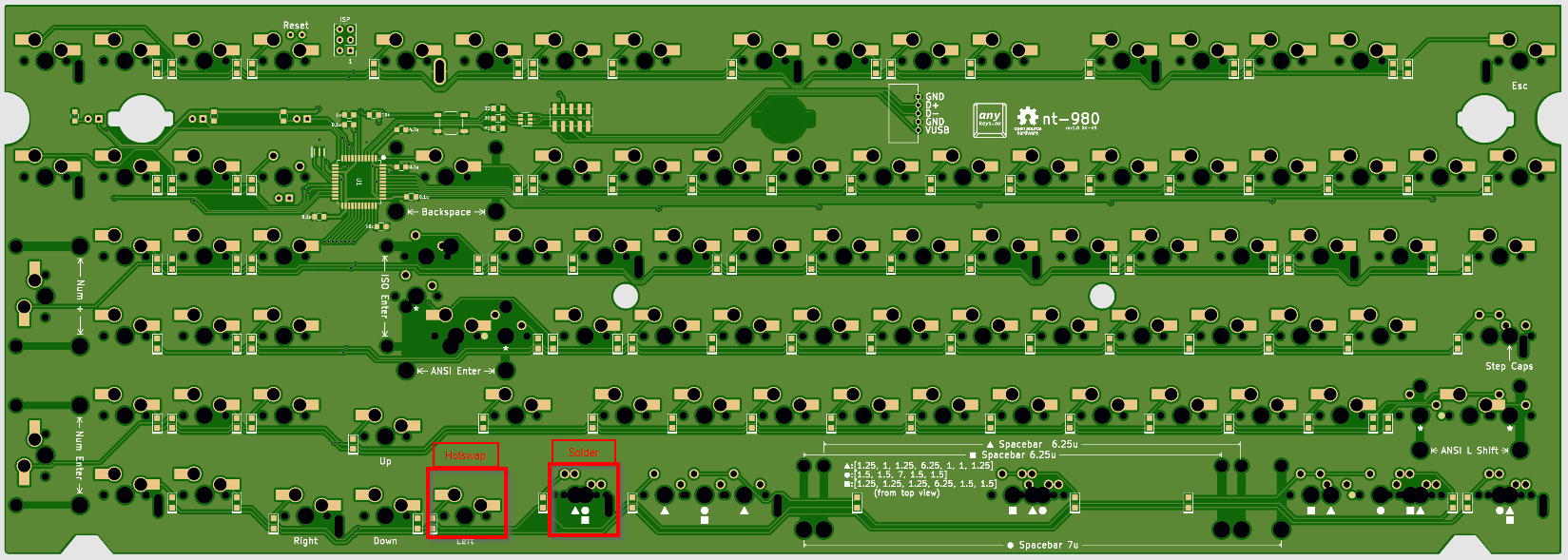
For the traditional FC980 layout 88 keys are Kaihl hotswap sockets 10 are traditional solder sockets. For my setup I am planning on soldering in Holtite sockets for the alternate layouts. So I can have the benefits of alternate layouts and hotswap (the Kaihl hotswap sockets are superior IMO rather then going all Holtite though I guess that is an option too if this idea doesn’t pan out)
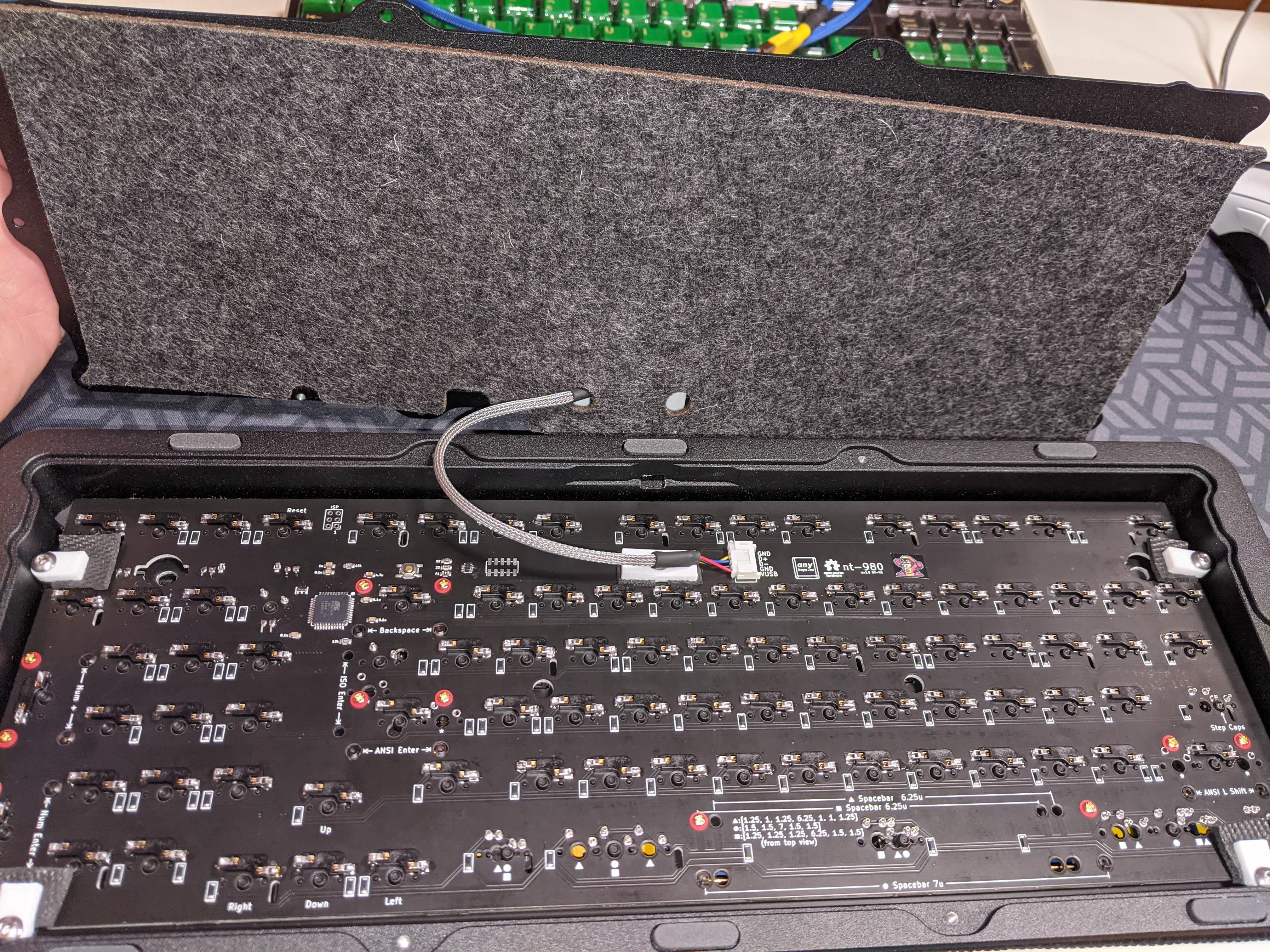
This PCB shot from the back might be easier to visualize the different sockets.
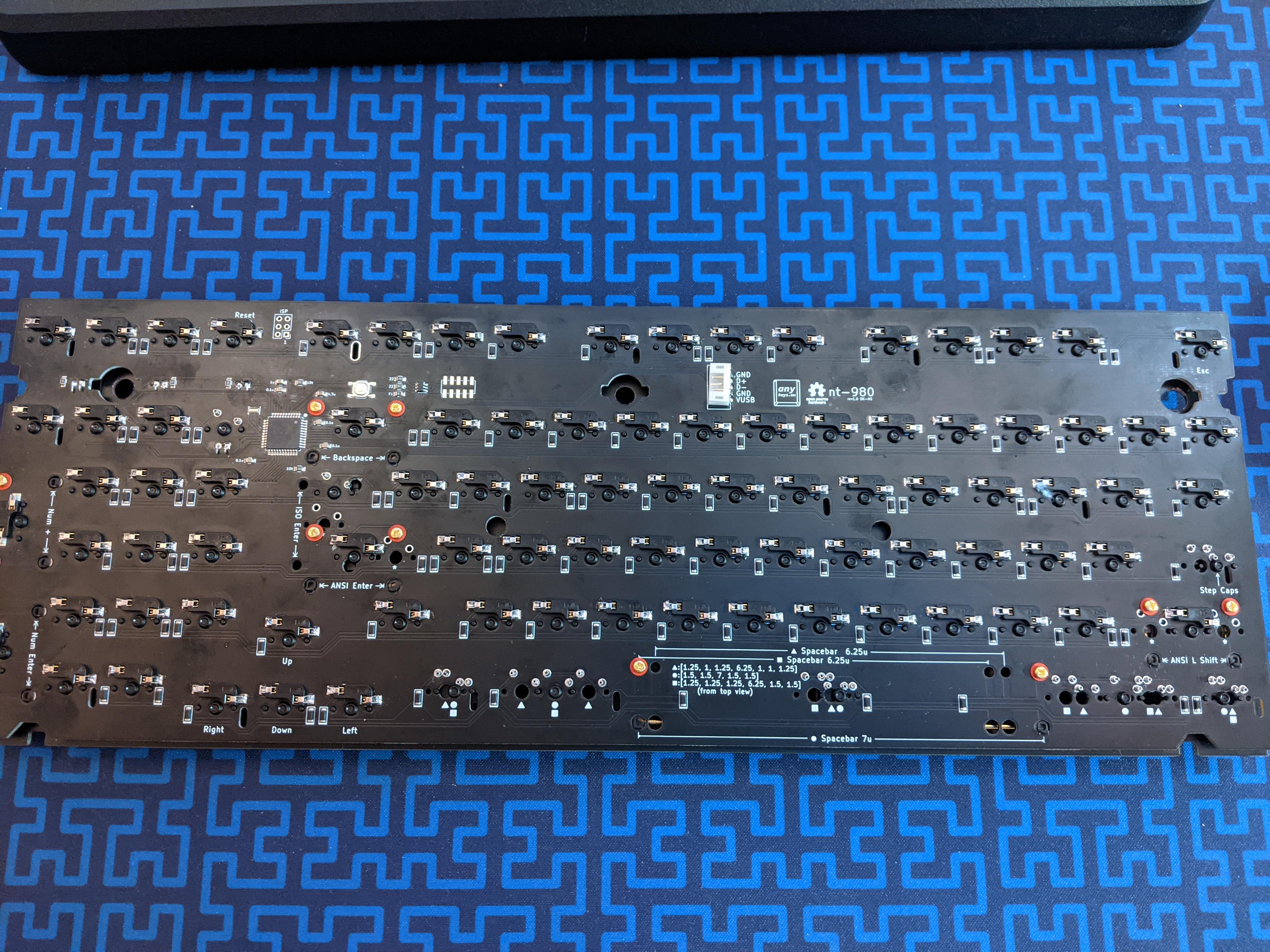
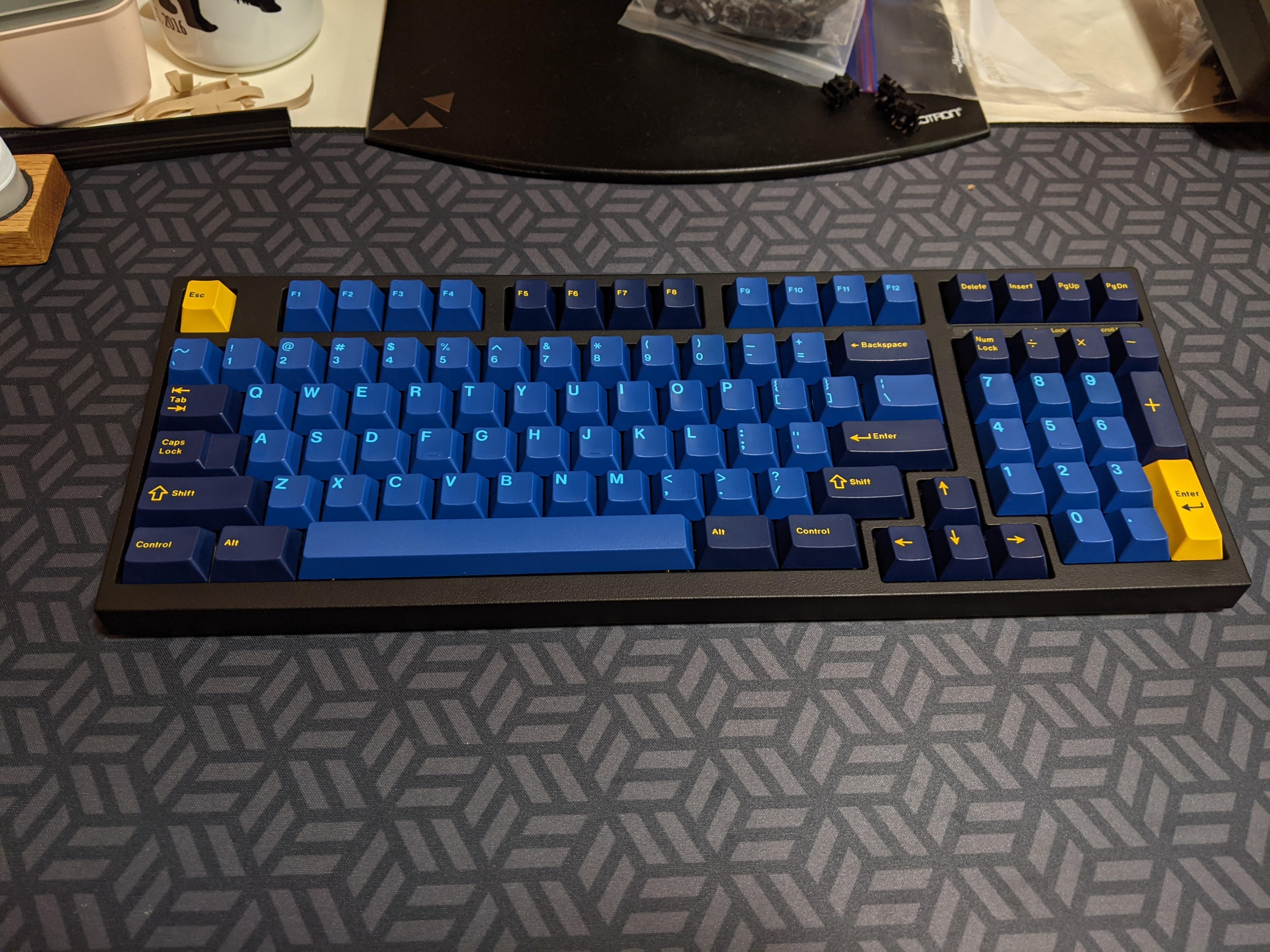
All changes from original worked! (markings showed up nice)
Black PCB is way cooler looking then the green one
HASL-RoHS finish is noticeably uneven when compared to ENIG fortunately those were over the surfaces being soldered anyway
The mix match of Kailh hotswaps and through holes turned out nice
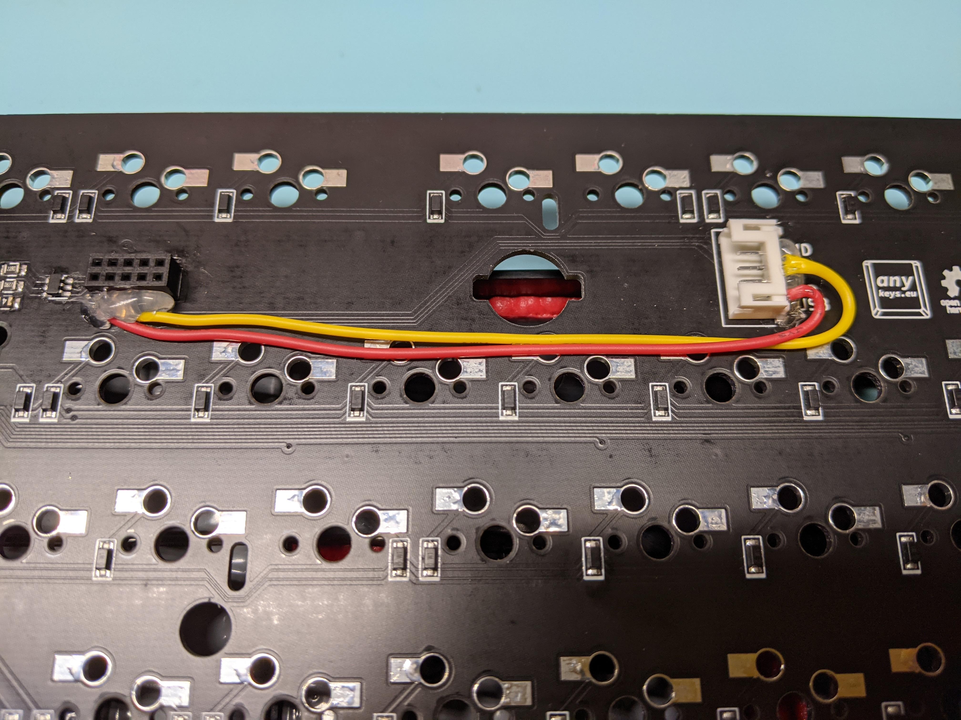
I need to to back and replace the JST connector it works but I have the proper part coming in the mail.
Going with 7u layout to start and see if I can get over the windows key muscle memory.
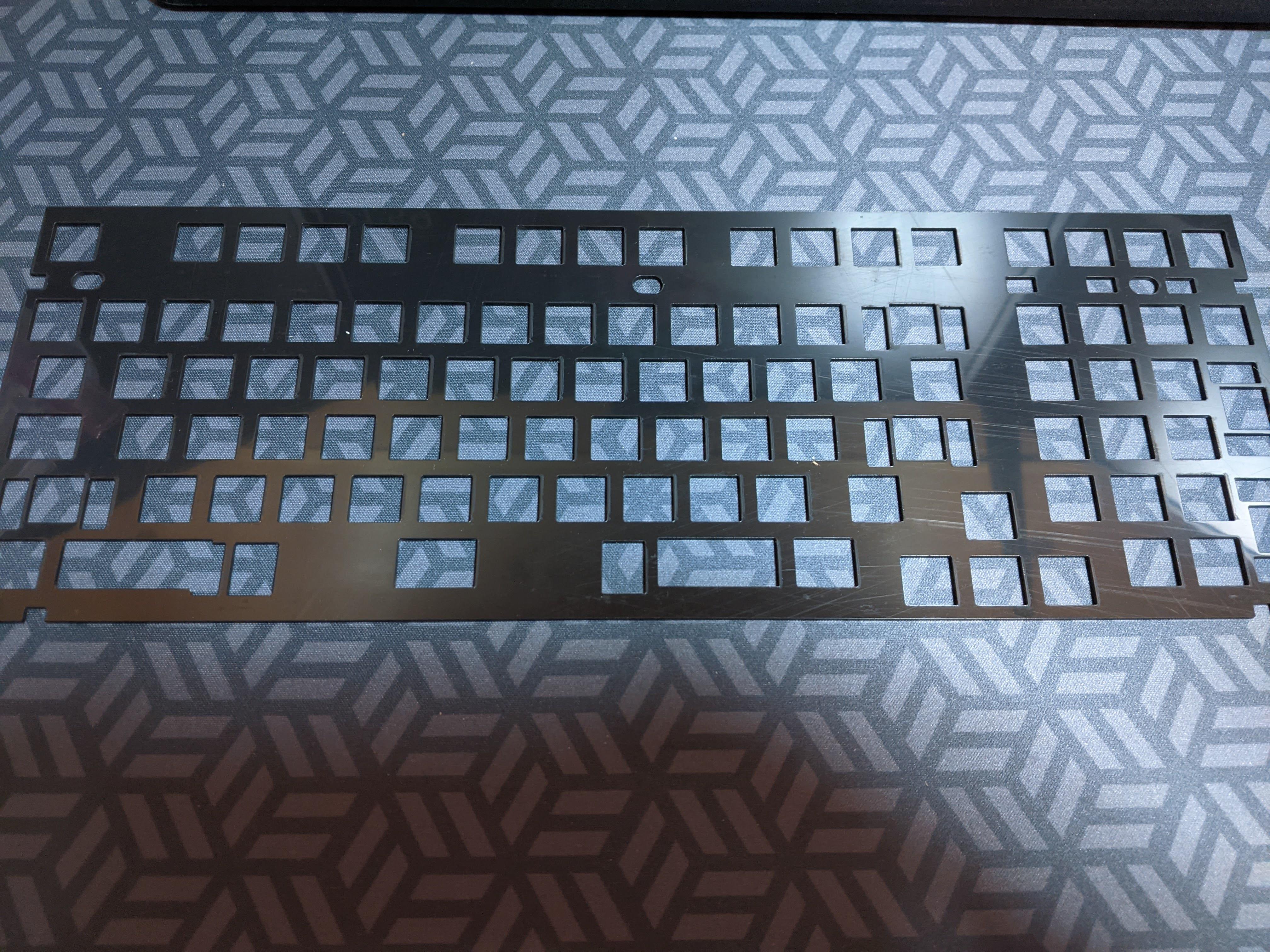
FR4 Plate: Ooopsies
2 of the mounting holes where slightly off. Not sure why I need to review might just change the hole shape in the future so I don’t need to worry about it.
Steps caps lock. Forgot to do this alternate position when lining up the dxf.
Good
1 it works (in both Heavy-9 and after some Dremel and Drill action the stock case)
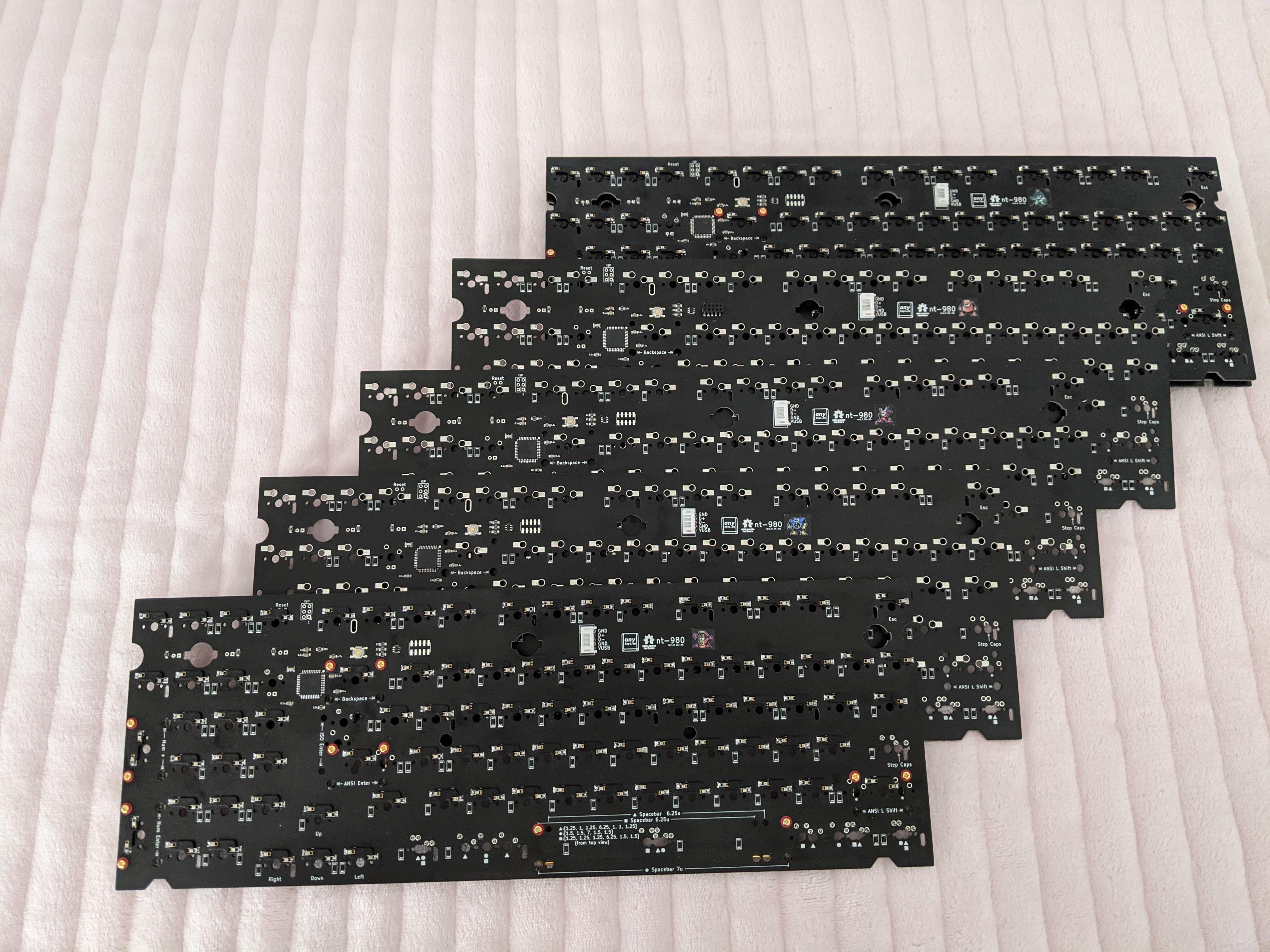
JLC made it with a black solder mask (their Gerber viewer was a bit messed up and gave a preview with no mask)
Its nice black mat finish I like way over the finger print magnet of Acrylic
^
Build Problems
Just including this here to show that things don’t always work out on the first try.
This whole process was very frustrating because in the back of my head I wasn’t sure if it was something I was doing wrong now or had totally messed up in the PCB design tweaks.
Things arrived and I was feeling pretty good. Installed the SMD components JLC didn’t have, resonator, MCU and ESD chip. Then tried to plug it in and nothing… After much testing around with a multi-meter everything appeared to be soldered correctly. So I started replacing components and still nothing. Asked/begged for help around and thought it might be the bootloader (or lack of bootloader on the ATMEGA32u4 chips. So built an ISP flasher with a pro Micro (followed this guide https://beta.docs.qmk.fm/using-qmk/guides/keyboard-building/isp_flashing_guide). Was able to decrypt the instructions and get it to flash the chip. Still not luck. Some more resoldering and nothing. I decided to try again with another new PCB and it worked.
Got through 50% of the switches and realized I messed up the plate steps lock key. Took everything apart again cut it and put it back together.
When I have more patience will go back and desolder everything and try again.
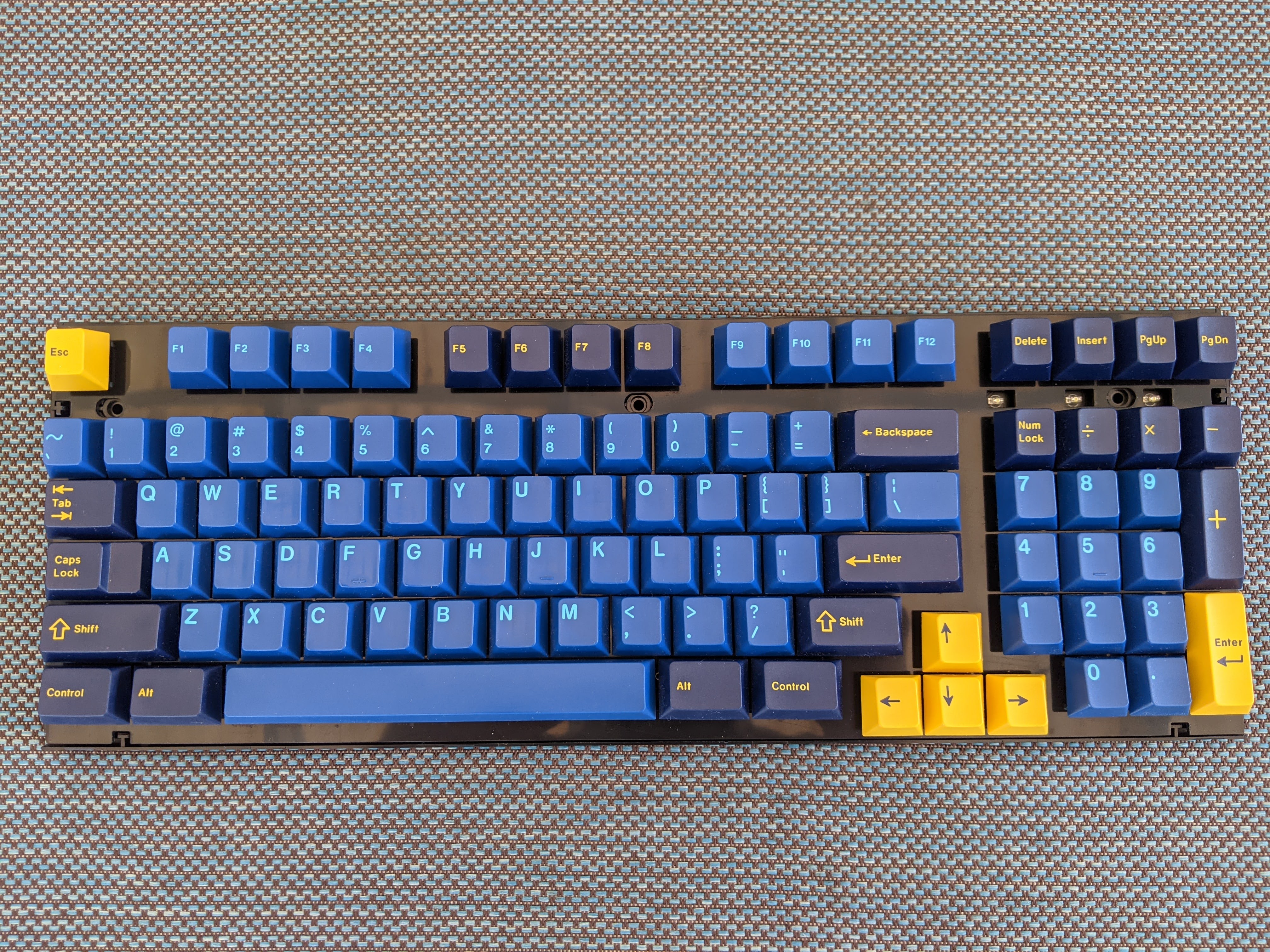
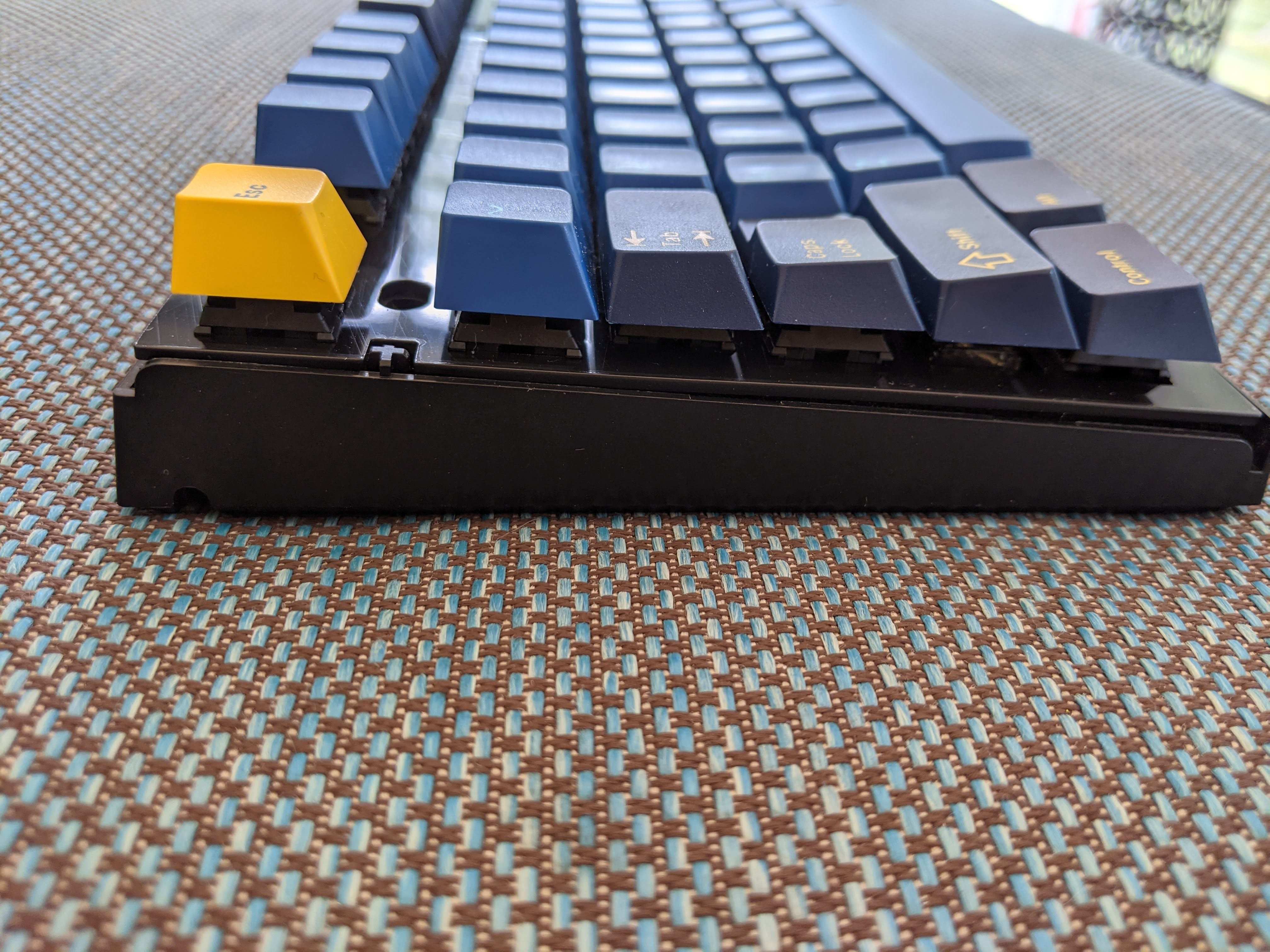
I redrilled all the circle holes between the numpad and escape key. The one near the escape key one was off by like 3-4 mm. The others were ok but tried to enlarge them to make it nicer. The caps lock mistake can be seen from the photo with no switches vs the one with switches.
I will do a more indepth photos with the stock case and comparisons with the stock plate that’s going to be a few weeks need a break from soldering. Planning on keeping 2 stock cases for decoy/guest/travel boards. I have an odd obsession with trying to get the yellow case one, one day mechanicalkeyboards.com…
yoooo i’ve been searching for the same board myself–its the 980M PD Parrot (the name in Asian markets). argh!!! please take your time i was just asking if you had the photos already off the top of your files. i’ll go back and look at those areas in your imgur album. but yes, the yellow 980M model has not been restocked on mk dot com for a while so i’ve been hunting for it in the aftermarket.
Regarding my connection issue. Was able to secure the MCU with solder paste using a stencil and hot air station. But that didn’t provide enough connectivity to all the pins (oddly enough provided enough connection on the pins to ISP flash though). I ended up using Kapton tape to hold the chip in place while drowning it in flux and using drag solder with an iron.
I am getting used to WKL layout just needed a few windows key shortcuts for open file explorer, lock and show desktop so it wasn’t too jarring to my everyday use.
I’ve been dreaming about building something like this but my skills at SMD soldering are severely lacking so I figured I’d just hope for a extras or a group buy to snag.
Did JLCPCB do the soldering and part sourcing work on this or was it only the PCB printing?
@PrivateAstronaut Thanks! This was my dream too (along with a metal case)
JLCPCB can do everything except:
10 pin connector: JLC just started offering this part, or I never noticed it until now, so I haven’t ordered it from them. It is a little bit intimidating to solder but isn’t too bad once you lightly tin a pad and tack it into place. I use an iron and solder paste.
JST connector: I don’t know if they have the part or not but I definately did not set up the footprint in the PCB design with a footprint so this part would need to be manually added. It is through hole so pretty straightforward soldering
Kailh Sockets: Not offered from JLC that I saw. I like to use a good amount of solder on tinning the pads then add the socket and use the iron to push each side down. That way the socket is super secure and less likely to pop off.
Suggest creating a JLC account and adding the Gerber, BOM and Place files to your order that way you can see what parts JLC has in stock. Once it is in your account you can back to your order at a time. So if you are waiting for a part to be in stock this is the easiest way I have found to keep track of everything. They have been perpetually out of the resonator C341521 but that part can be replaced with this one C882606.
JLC Oddities: Just a heads up the JLC steps of “Select the parts” & “Review Parts placement” are a bit messed up. They give weird quantities for some parts like for example 6 or 9. That doesn’t make any sense as neither of those are divisible by 5. The “Review Parts Placement” never actually shows the part placements. These things are straightened out when you complete your order (for quantity). And a few hours later when they do an analysis of the order. Also their Gerber viewer can be a bit wacky and not show cutouts (or show cutouts in a different color). I have no idea why it does this but others I have talked to experienced the same thing with different PCBs on the viewer but they came out okay when manufactured.
The good/bad thing is JLC makes you order 5. So you have 5 tries to get it one working :). Extras you can sell to recoup some of the costs. If it gives you a confidence boost, I have only done this twice but I was able to figure it out both times and have documented the process here.
You wouldn’t happen to still have any extras from this order would you? Stumbled on a malfunctioning version and this would be a sweet upgrade…
And since the answer is likely no, what was the total cost to order the 5 PCBs?
Sorry, no I don’t have extras. A few people on KeebTalk and Reddit contacted me and I sold what I wasn’t going to use (yay first MechMarket transactions)
In regards to cost:
1st round ended up being $35 per PCB (Choose ENIG finish and a few other options that drove up the cost). Sold a few for $40 and send the designer, evyd13, $5
2nd DK HS Version $47.58 per PCB. This was due to the cost of the different types of hotswap sockets and having to source materials from multiple places
It can be done cheaper depends on what JLC has in stock and the version being made.
In the next few months, I am going to be making a final revision with Sarvopari that has all solder sockets (so basically my HS version but with solder sockets instead and maybe some minor tweaks). There probably won’t be an extras from that run because don’t want to order a bunch a find out something is wrong with the design.
Sorry for the long post I have been working a few things trying not to leave too many incomplete projects.
Plate
Released files for different layouts. ISO is not my thing but I did create the necessary files since a few people had mentioned it. Have only made the Alternate Layout version the others **"should"** work.
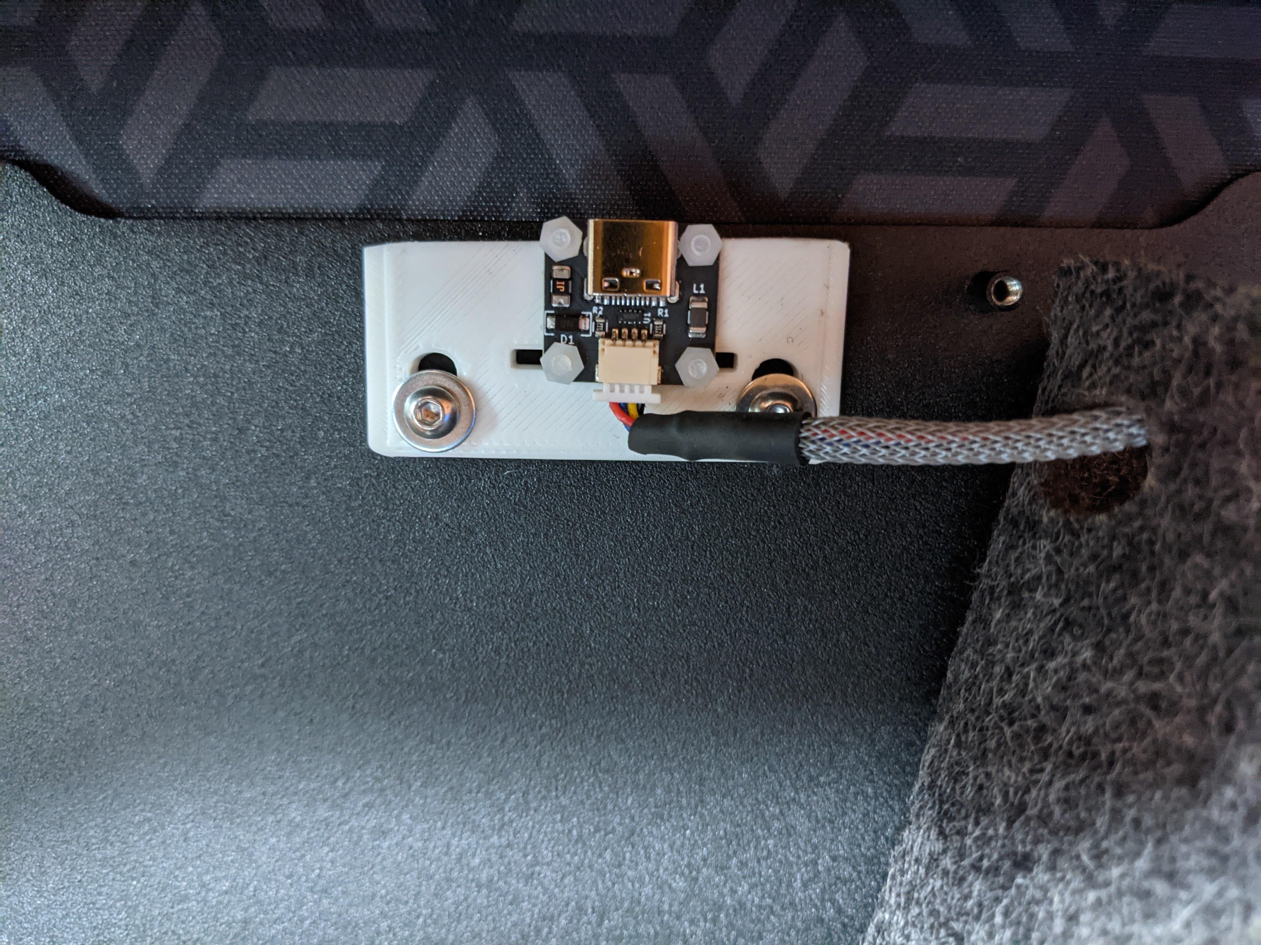
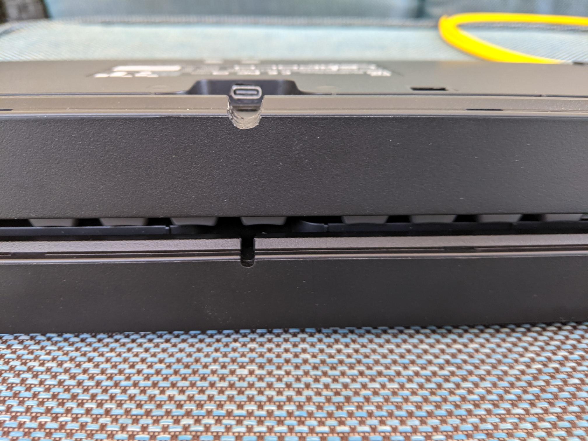
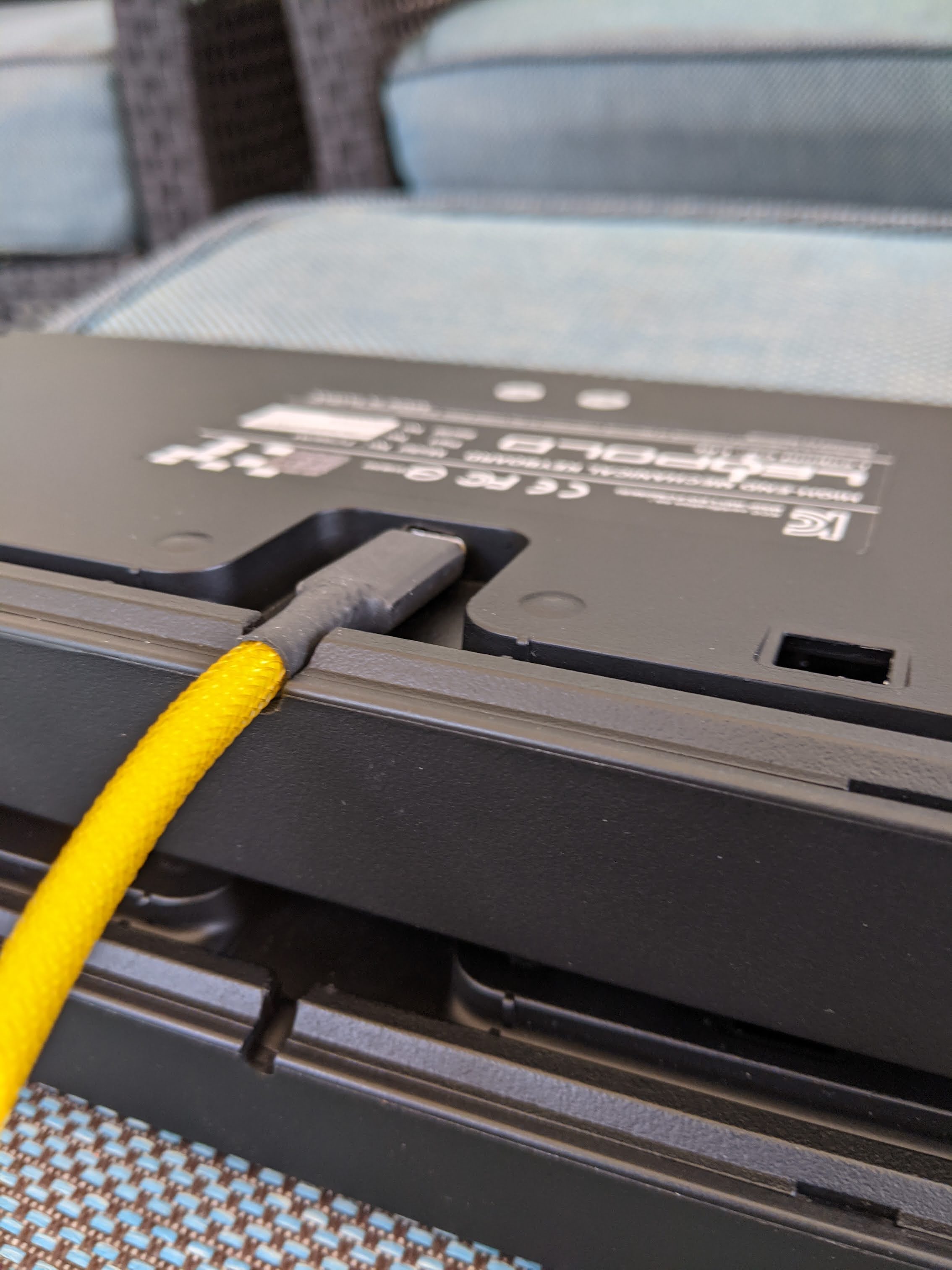
Cleaned up my implementation of USB-C in the Heavy-9. Wish the inside of the Heavy-9 USB C hole was cut slightly flatter in the back but not enough to risk taking the Dremel to it. My 3d bracket was ok worked and allowed for adjustments. Still need to get some metal screws though, plastic ones very flexible. Sleeved the cable to make it look nicer and the cable fits in the pre existing holes so I didn't need to make any cuts.
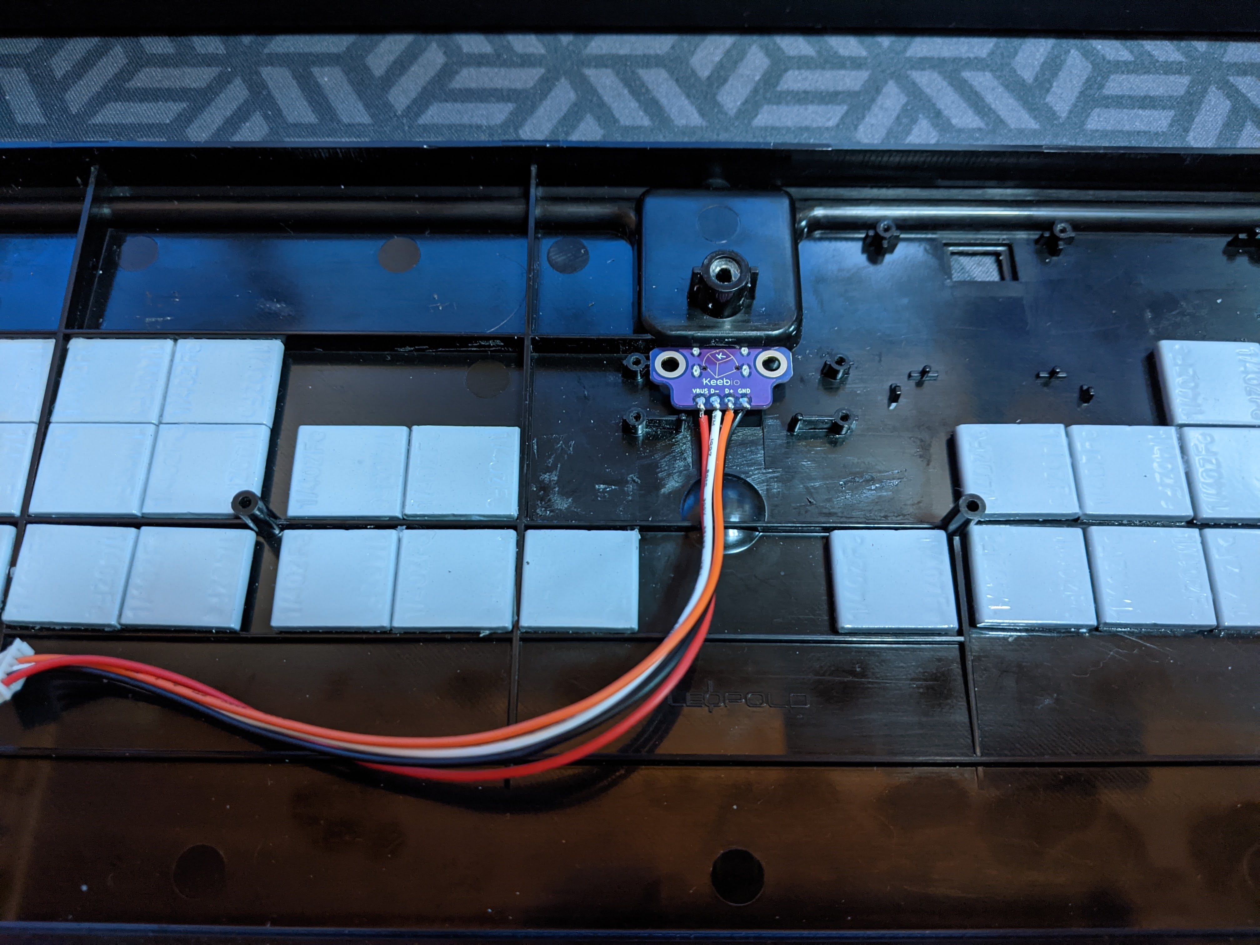
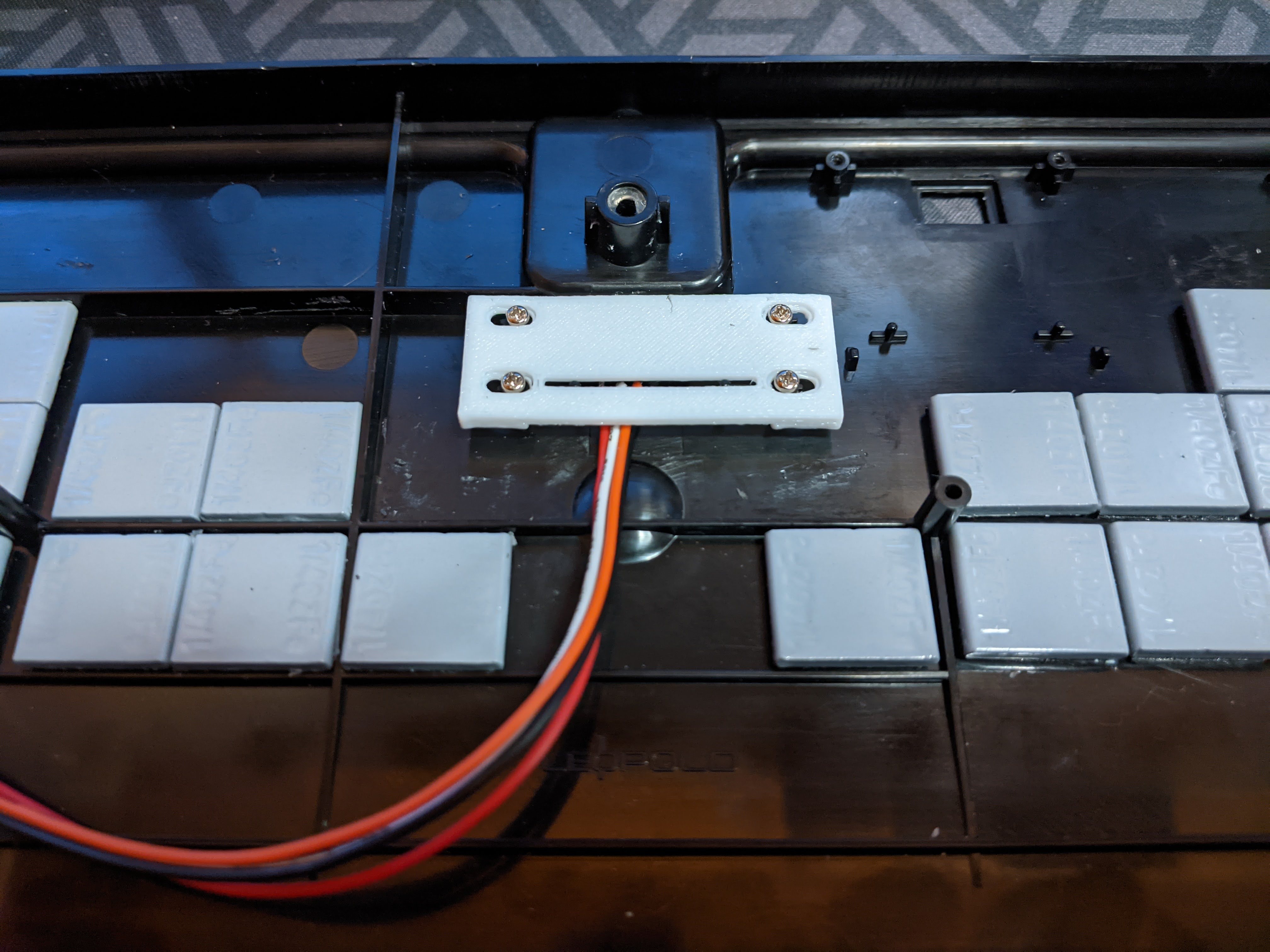
Converted remaining stock case to USB C using a Keebio breakout board https://keeb.io/products/usb-c-breakout-board and 3d printed bracket designed by @tinster4x4
Enlarged the USB channel on the stock case to accommodate a custom cable with a Dremel buffing tip in increasing sizes until it was big enough for the cable.
Above modified below stock
Hi Dave, would the plate files that are released above fit the stock case for the fc980m? From the looks of it, it does look like it will fit. But I just want to double-check if it does. I just recently purchase the nt-980 PCB from a user on reddit but only have the time to really start working on it right now.
Hello @Cawfee if it had a megaman boss sticker on the back it was probably me.
Plate files do work with stock Leopold case. Some of the photos above in the previous post were in the stock case. Once the top part of the case is put on it clamps on everything is very secure. I used it for a few days no problems same with the fr-4 plates I made previously.
Oh then I did purchase it from you, and I’ll definitely try the things that you did to make it has USB-C for sure. It’s an interesting project that you started. Also ty for the clarifications.
Would your plate work in the heavy 9? I am debating getting a MX setup for mine and I have been keeping an eye on this project - seems like I would still need to buy a 980m for some parts, then your PCB and plate?
Yes plate works on heavy-9 but if you get a flexible non metal plate you need a few 3d printed parts or an alternate solution (there are some photos above of the internals of the heavy-9 with this setup). I am reorganizing my GitHub repo is a bit of a mess but files are here: nt-series/nt-980/heavy-9-adapter at main · davek184/nt-series · GitHub
Do you need a Leopold board? No*, as long as you are comfortable doing the USB c mod. It can be done with a universal daughter board or keebio breakout board. The USB port does sit deep in the heavy 9 bit I haven’t had a problem using it and I am happy not to deal with mini USB.
Note there are 2 PCB designs. The original and mine. Mine has the secondary USB connection the original only has the 10 pin connector. That 10 pin connector can be removed and a JST PH 5 pin connector can be used, depends on people’s comfort level making such a change (I totally screwed it up first time). Next month I will finish my design version but in full solder sockets.
If you already have a fc980c the mini USB daughter board is interchangeable. That can be used if you are unsure.
now you got me thinking about modifying your plate to use cutouts sized for niz housings, and then using plate mounted stabs (gmk or costar) to make a custom MX 980c version… just the plate to pcb attachment issue.