I think it can rest on the 3 big divots in the case. Plus there are 2 support pieces of plastic that go through the PCB and support the plate. The bend does perfectly line up in the back which does give it more strength but I feel it can so without it. When it arrives if it feels insecure I am sure I can find something to stuff in the case. Will take photos of the progress as it comes along.
1 Like
Spent a good two hours last night desoldering the stock fc980m PCB from its original plate. The soldered hook (I imagine for grounding) was a huge pain in the ass to detach. It has a weird/complex shape with factory solder that was on top, inside, underneath, etc. Decided to just cut into the PCB with an exacto and file away the remnants. To be frank, I don’t know the purpose of any of the hooks, nor the bent edges on the plate. A simple suspended PCB held by the switches would have done just fine.
1 Like
I found that if you add some solder, heat it up and then slide it out. Idk how you would of it otherwise. The only purpose of the soldered hook is to ground the pcb. I think…it’s pretty odd.
Ordered a custom Acrylic plate from Ponoko following the instructions in this thread: Tsangan plate design files
I wasn’t able to modify the DXF file for the mounting and edge cuts. Every time I touched or converted the file to SVG it would mess with the measurements. So I left those cuts out and made with a Dremel tool and a drill. The Dremel worked okay if you went on the slowest speed and really took your time (same with the drill although didn’t have to go quite as slow). I should have drawn a centerline across the plate and used that as a reference point when drilling. (I should have also spent more time on the DXF so I didn’t need to do those cuts by hand).
It is much lighter. I have tire weights and a poured silicon dampener in mine so its still heavy but noticeably lighter. Typing experience it is a softer bottom out which is what I was looking for. Sound wise I recorded a before and after. I am using Boba U4t switches unlubed (waiting on another part to go back and lube them). The plate is a fingerprint magnet.
Overall I am happy with it. PCB stabs are awesome, I was stuck with plate ones before and these are better IMO and easier to tune.
Regarding Heavy-9 case this plate will never be able to handle that mounting system. Its too thin and flimsy compared to the OEM steel one. However, I am hopeful a few 3d printed parts can be made to extend the load to the PCB and it can work (we will see hopefully I have one coming)
OEM Steel Plate
Acrylic Plate
Pictures (my phone couldn’t compensate for basement lighting and the blue mat, I need to stop taking pictures downstairs or get a real camera…)
https://imgur.com/a/AgR7X5u
Holding off on alternate bottom rows for a little bit. I have the designs ready but JLC is out of a couple of parts right now.
4 Likes
Just realized I shared the post below on the Heavy-9 thread by mistake instead of here. Linking for prosperity.
1 Like
Hi everyone - just happened to stumble across NT980 and feeling a bit lucky to have come across this relatively recent thread. Thanks @Dave for the through guide, but I’m wondering if you or anyone else here ordered multiple and happen to have an extra to sell me. I’d rather not order 5 PCBs if I didn’t absolutely have to. Thanks!
1 Like
It’s probably for ESD protection
1 Like
I’m really into this! I want to do this mod and convert an ANSI board to ISO, but I have serious doubts about my ability to fabricate or otherwise get my hands on a custom plate.
1 Like
im just gonna put interest in GB for plate+hotswap pcb. i am aware other 980 hotswap options exist (FLESports 980) but i want one that is drop-in to the leopold plastic cases / possibly a heavy9 in the future.
2 Likes
Offering my extra PCBs here if anyone is interested. Finally got around to reseating all the misaligned diodes (as discussed above) and tested in VIA – they are all 100%. PCBs will come already flashed with VIA as well as the connector soldered on. Will update this message if/when they’ve all been claimed.
2 Likes
You could try using the Dremel on the existing plate and use a PCB stab. That way your cut wouldn’t need to be too precise. Even if it is a giant hole as long as you solder in the switches you should be good.
Heavy-9 with a non metal plate needs some different mounts otherwise it is too flexible. I am testing this setup now.
2 Likes
You could try using the Dremel on the existing plate and use a PCB stab. That way your cut wouldn’t need to be too precise. Even if it is a giant hole as long as you solder in the switches you should be good.
I see. Alright, I guess I’m doing this then.
1 Like
Definitely interested in acquiring one of your extra PCBs. Let me know how much you’d like for one and we can sort out the details.
In my spare time, I am learning KiCad and how to read some of the nt-980 PCB details. Taking a closer look at the PCB connector to the original daughterboard I saw only half the pins are used. Which makes sense as only 1 of the 4 dip switches does anything with the nt-980. So the daughterboard can be bypassed by using JST 2.0 pin connector instead of the 10 pin original one. This might be useful to someone who doesn’t have or damaged their original daughterboard.
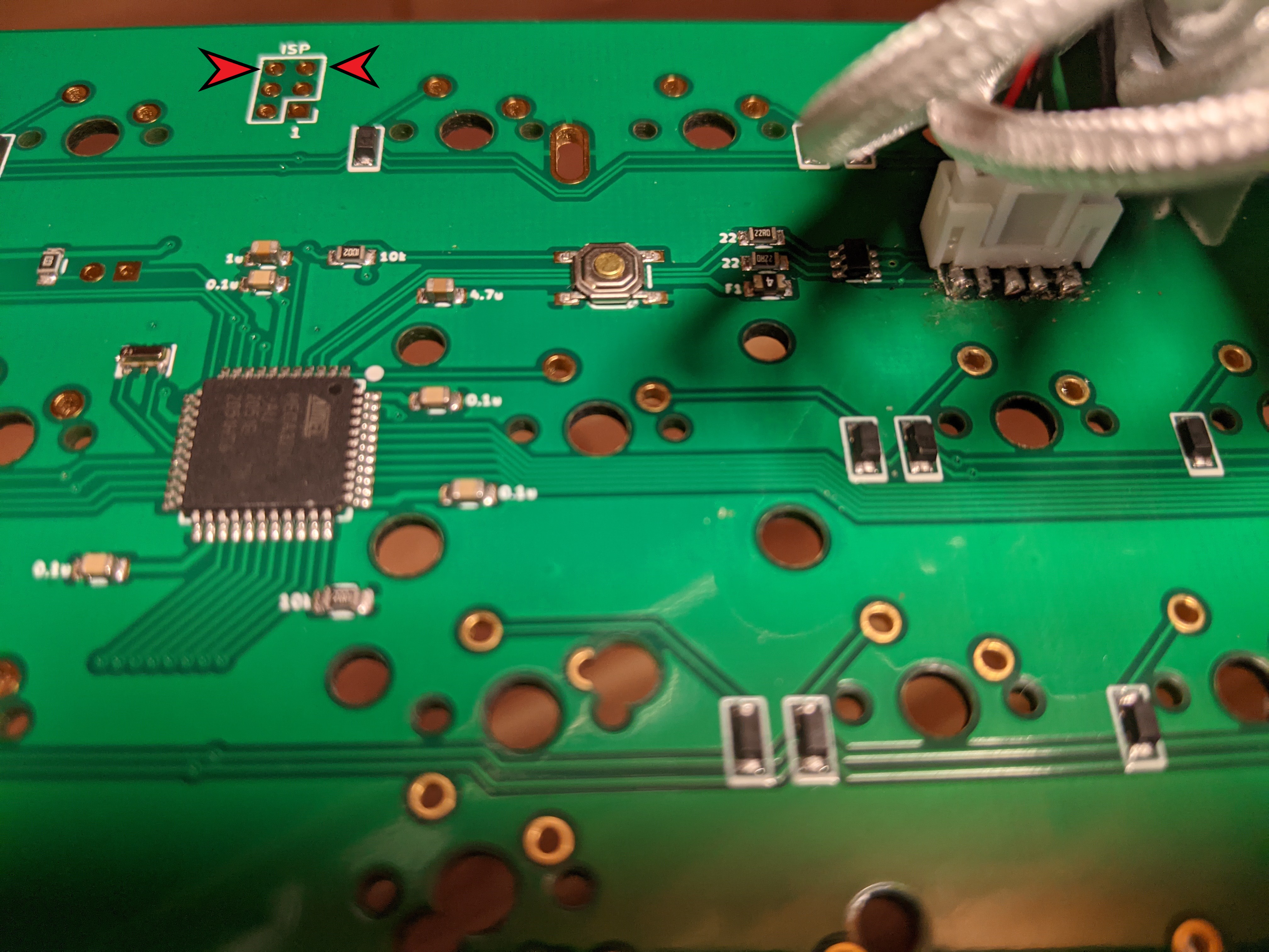
Alternate way to go into bootloader mode short the 2 holes with red arrows in the picture.
Note: I did learn the hard way to always triple check wiring before connecting. Was looking at the top view of the PCB in KiCad and didn’t realize it because zoomed in pretty far. This swiftly fried my extra PCB. Fortunately it was an extra so I wasn’t too upset. I did confirm with a different PCB and the original oem PCB it does work properly.
3 Likes
Just found this thread. Super interested to do this myself. I also found a bluetooth adapter for the FC980C. What do you guys think about it working with the custom PCB?
@HonestIago
That controller is specific to the fc980c output and wouldn’t be compatible. There is a similar one for the fc980m (it’s occasionally on AliExpress) that someone might be able to finagle to work but would be hacky and expensive.
Bluetooth details is not something I know too much about but in theory you could get a generic keyboard to Bluetooth USB stick. Then bury most of it in the case.
Alt, in theory the MCU could be changed to accommodate Bluetooth. Beyond way beyond my still set.
Bluetooth has been a thorn in my side with my desktop (I tried multiple dongles). Less so on my laptop. When I want to use my keyboard I just want it to work right away without messing around. My headphones are bluetooth which I accept my daily turn Bluetooth off and back on daily and things mostly work ok.
I wish something like the Logitech unified receiver was open sourced and could be incorporated into non Logitech stuff. Maybe there is an open sourced rf transmitter and receiver out there.
For anyone who’s planning on removing the plate, after spending a bit of time trying to desolder this with a solder sucker and solder wick, this heat-and-slide method was the one that finally worked for me.
2 Likes
I’ve can confirm that BT dongle is NOT compatible with this particular custom PCB. I got a yang 980M BLE and it’s running a custom YMK (closer to via) for BT and works incredibly well, but it can only work with the stock PCB.
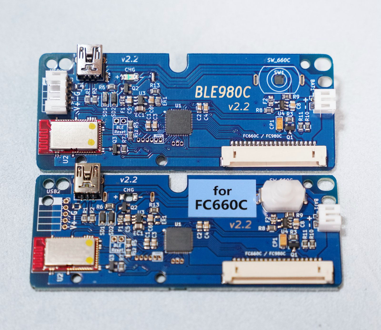
Additionally, I noticed that the mini USB B and a 5 pin breakout. I’m not entire sure what’s that for, but I prefer to install a custom USB C port.
1 Like
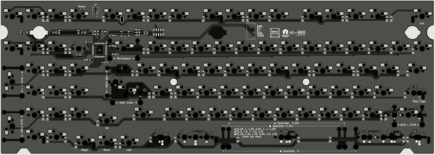
I have been working on altering the open source design to learn a bit more and see were I could put my spin on the PCB design. All credit still goes to the original designer without that I wouldn’t know where to start.
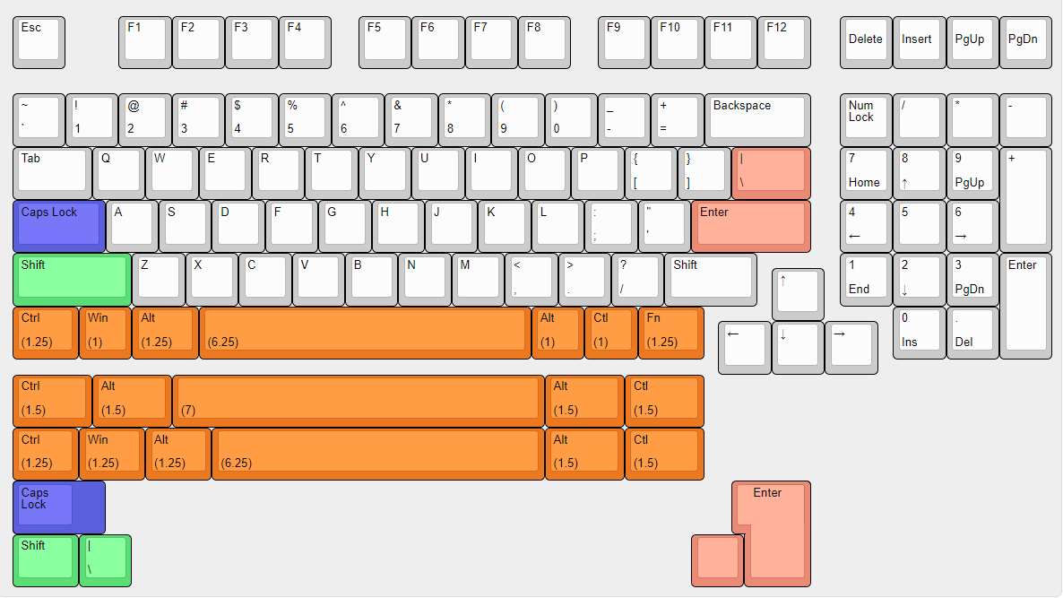
- Bottom row layout options
- Stepped caps lock option
- Labels for alternate layouts. Tried something a little different with shapes on the back to quickly ID the layouts quickly and easily (that is the idea at least)
- Numpad Enter and Plus rotated
- Added alternated LED location under num lock key
- Additional Reset pins under delete key
- Added second USB connection (JST 2.0 5 pin).
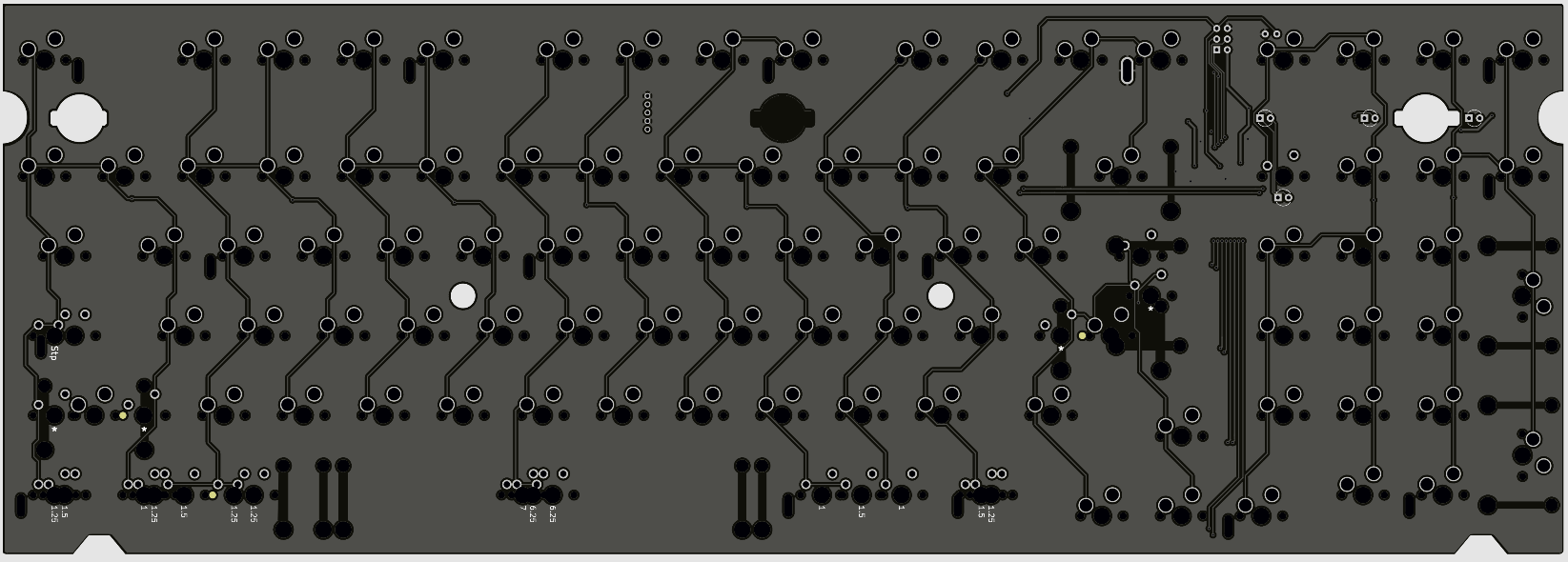
Retained the original connector in the spirit of the original design. The alternate position can also be used with the stock case but eliminates the need for the Leopold daughterboards. - Converted most but not all the key positions to Kaihl hotswap. (The coper rings around the hotswap holes don’t do anything I just thought they looked
 )
)
Why because I have switch and layout commitment issues. I thought this could potentially be a good compromise where I can have my cake and eat it too. I get mostly the better hotswap sockets yet I can still have the alternate layouts I want. When this works I can make a fully “normy” solder version for those less adventurous .
Thanks to @tinster4x4 @sarvopari & @Rico for helping me out and letting me bounce ideas off of them!!!
Next step is to work on the FR4 plate and place an order. I think I am about a week or so out. If anyone has any comments let me know and I will consider adding them. (Will also make a gitHub repo for this after I confirm it works). Due to part shortages, I have to solder the MCU so JLCs minimum order of 5 PCBs will probably work in my favor I mean I can probably do it right at least 1 out of 5 attempts 
Layouts (originally supported split left shift and ISO enter added bottom row and split caps lock)
(Edit: Corrected typo in original)
Front:
**
Back
7 Likes
electronically illiterate here: can i just confirm that v2 run of the pcb will be hotswap? what were you saying about
will the standard fc980 layout (first orange row with 1.25 Fn–i think that’s a typo in the diagram?) be hotswap? or do i have to ask you to do it if I order a pcb and plate? i’ve purchased a second 980M and would love to get a hotswap pcb and plate for it.