Long story short, my current project is to Topre-fy one of my existing boards. Outside of components that I can purchase, the last thing I need to make is a plate file and have it cut. Thankfully, I have the project board file as well as a generic file for the PCB. What’s missing is my knowledge for how to utilize them both to create what I need.
I have access to a .DXF of the board plate and a .DWG of the generic Topre plate file. Despite my best search efforts, I’m struggling to find a good resource to learn how to do so. My free time is somewhat scarce but this is something that I’ve wanted to learn for a while now anyway. Does anyone have any advice or tips on where to start?
What you’re looking for is drafting software such as AutoCAD that can modify DXF/DWG files, specifically the sketches. From there once you’ve located a suitable software, you need to open both in the viewers and look at the dimensions that are used such as the switch and stabilizer cutouts and then modify your plate file to match the switch cutouts dimensions of the generic Topre file. You might need to adjust the key spacing as well if the Topre spacing is different from the standard MX spacing of 19.05mm, or also the plate thickness (but thickness is material dependent).
Apart from those few things I don’t think there’s much else that differs between MX plates and Topre plates, but I could be wrong. As for CAD software LibreCAD is one of the free ones that I found on Google and it seems to be capable of modifying 2D sketches.
Very helpful! What I was effectively hoping to do was take the outline of the Frog Mini plate and replace all of the switch and stabilizer cutouts (aka everything but the perimeter of the plate) with the generic Topre plate. I’m not sure how feasible that is but that’s my intent, anyway. That way all of the spacing is correct and the plate itself would likely be a firmer plastic or aluminum so that it’s sturdy enough to place switch housings in.
Is the Topre plate a 60% plate with the same layout as the Frog Mini? If so then it’s easier to modify the Topre plate to match the external dimensions/outline of the Frog plate instead.
There’s an option for it, yes. So effectively what I was hoping to do was take the outline of the Frog Mini plate for compatibility with the case and then everything else from the EC60 plate, if that makes sense. I only have the DXF of the Frog Mini plate but there’s a PDF of the EC60 plate to hopefully help better illustrate what I’m after.
That is incredibly awesome. I adore my Frog mini, and would love to be able to swap out to Topre on the fly. One of my favorite things about the frog boards are how easy they are to get into and mess around with the build. Very cool.
Here is a pic of the plate. Last I heard, he was making additional tweaks to alleviate from having to make a few post production modifications; namely, having to cut some of the housings to fit the stabs
I mean, either way he did it and that’s a feat unto itself. He used full right Shift though so I’d have to modify that to split either way. Thankfully Cipulot has the layout that I want, I just have to graft that into the Frog Mini plate outline.
In looking at his a bit closer, it looks like that’s exactly what he did given all of the screw holes (that the Frog doesn’t use) matching up with Cip’s file.
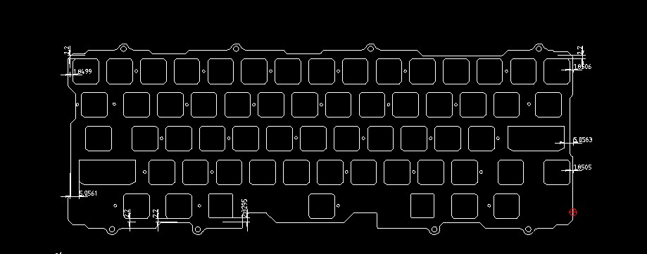
Perhaps further illustrating that I have absolutely no idea what I’m doing, I’ve at least managed to take the Frog Mini outline and mate it to the EC60 HHKB layout.
The measurements are leftovers from the generic plate - I’m not sure they’re even useful anymore but I’m leaving them for right now. The trick is going to be determining how exactly I check my work to figure out the placement of the outline. I’m thinking that maybe I get a caliper and measure one of the plates that I do have and use that to get me close. It’s too big to print paper dummies on 8.5x11 paper but that seems like the first step to QC it.
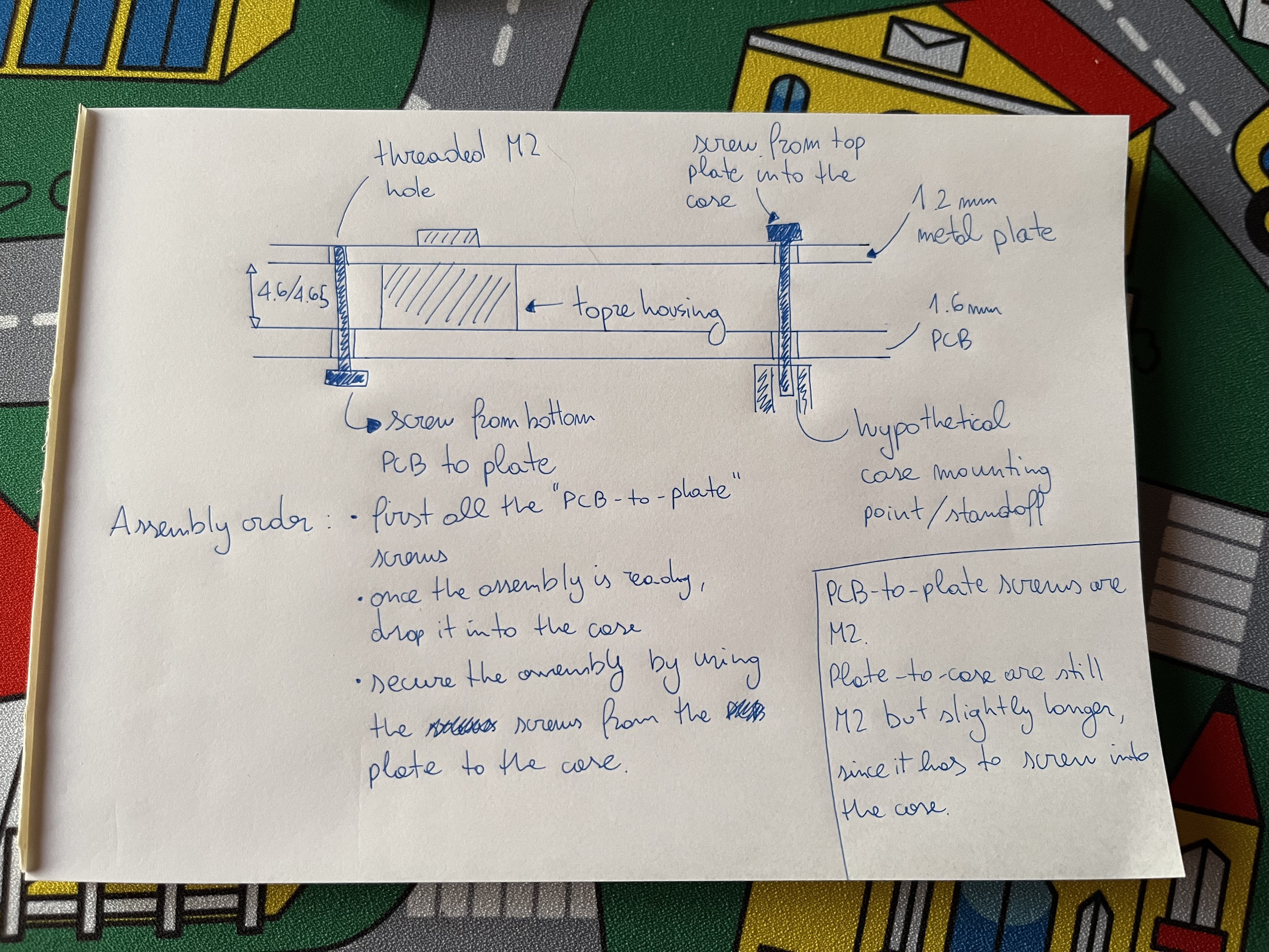
Unless I’m wildly mistaken, the housings should handle the spacing between the PCB and the plate. The PCB screws into the plate using 29(!) M2x6 flat head screws, which I’ll probably end up ordering from McMaster Carr.
Depending on the material used I’d either tap the holes for aluminum or let the screws do the work with a plastic.
so the screws just go through the back of the PCB into the holes on the plate? I guess 1.5mm is thick enough to hold the screw since not much pressure is applied?
Well, again I’m going this with basically zero source material so my ignorance is going to show. The only Topre experience I have is with HHKBs. I may have to track down some stand-off replacements (if they exist) just to have on hand as I’m mocking this thing up.
I do think I’m going to go ahead and get a digital caliper. Since MX switch cutouts are the same as Topre, I should be able to measure the MX plate that I have on hand to figure out the Topre version and then create a paper mock-up.
in standoff-less topre the 1u and 2u housings basically hold it apart/together.
it does feel different from OEM that has the soldered in/metal standoffs/inserts. OEM feels the firmest, most secure, and also has a better sound (preference.)
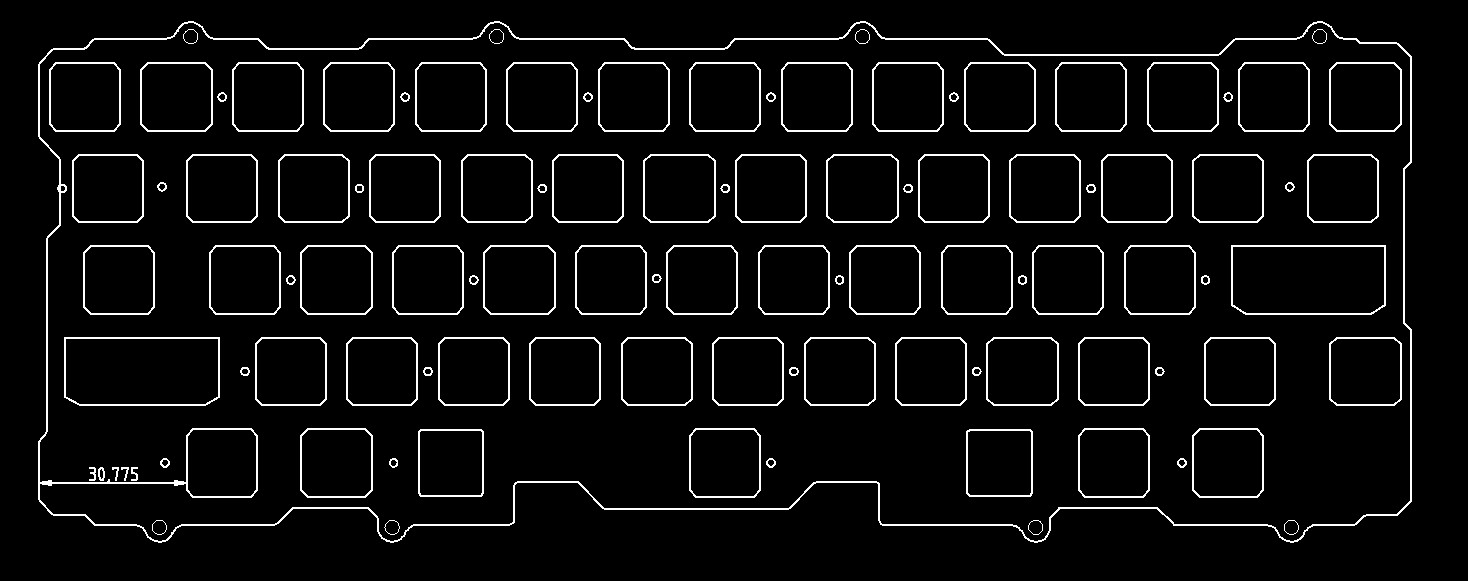
Progress.The Frog outline is now centered on the EC60 internals. This is a lot trickier than I anticipated since the plate is so asymmetrical but I think I’m headed in the right direction.