Power delivery traces are all 20 mils so no worry about that 
2 Likes
Oh nice that perfect 
1 Like
I was happy to receive my PCBs from JLCPCB this week.
Those came out good … mostly (I’ll get into the problems).
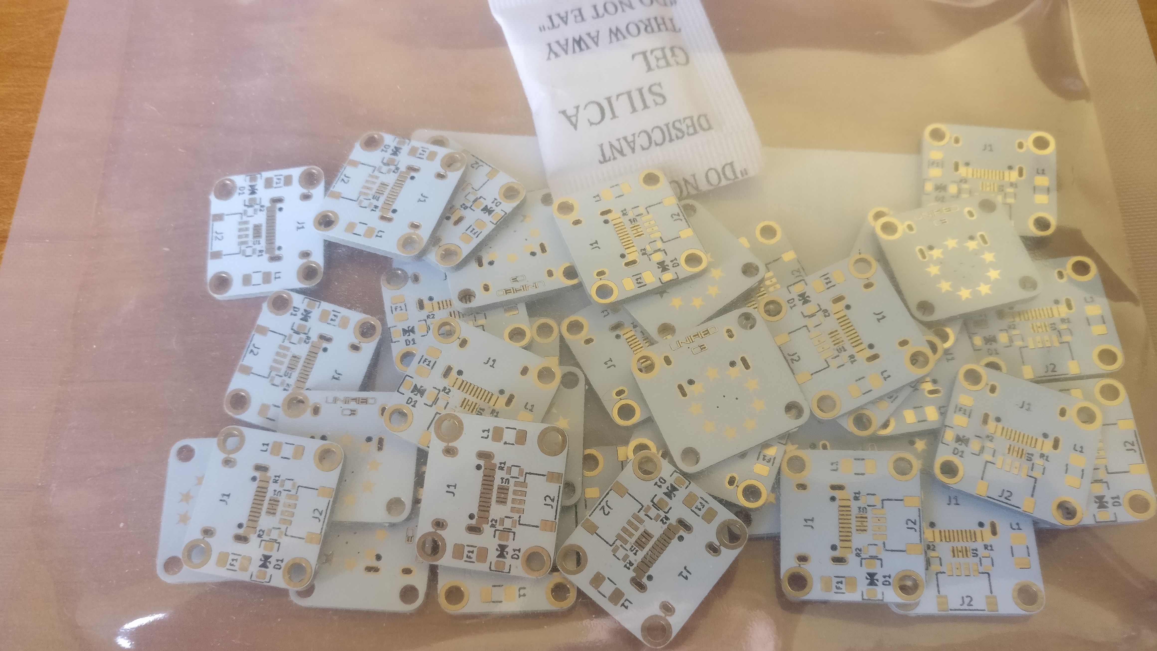
First, the USB C3 daughter boards (lots of them).
For those I will solder them myself (still waiting for some components).
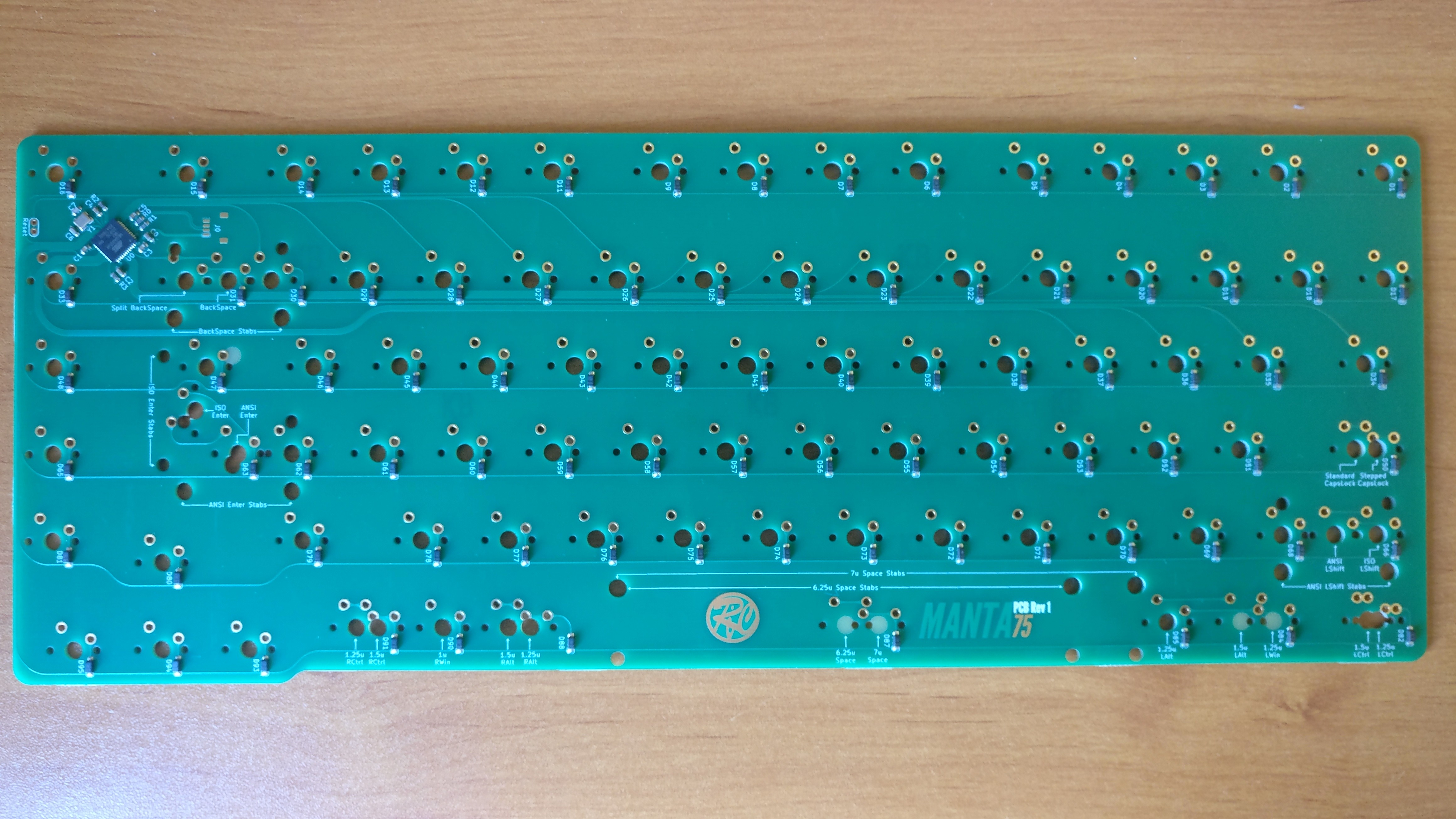
Then the main PCB, using the assembly service.
The assembly was very well done (could not have done better and with a lot of time), the solder mask color makes the PCB beautiful, even if using boring green.
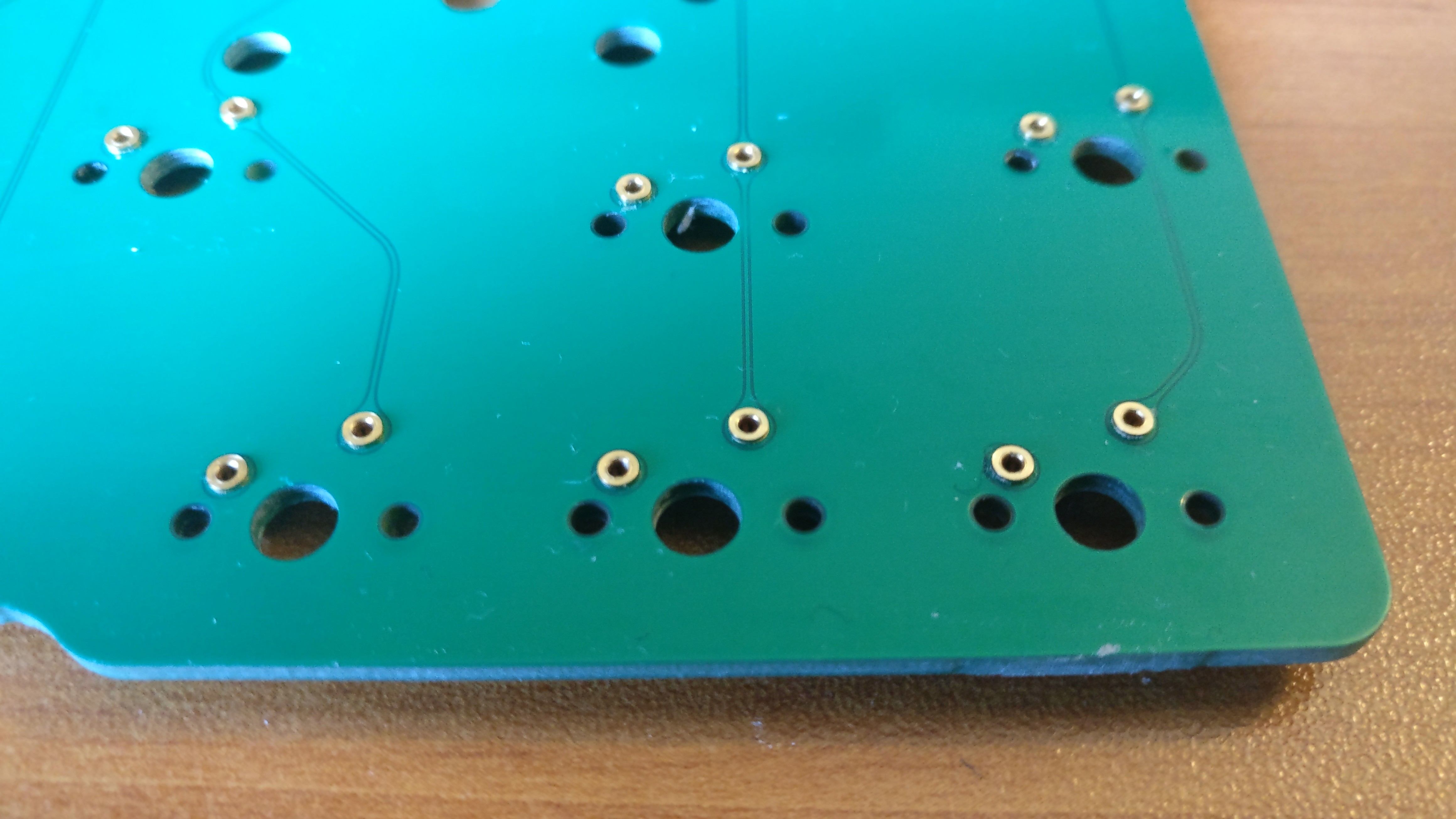
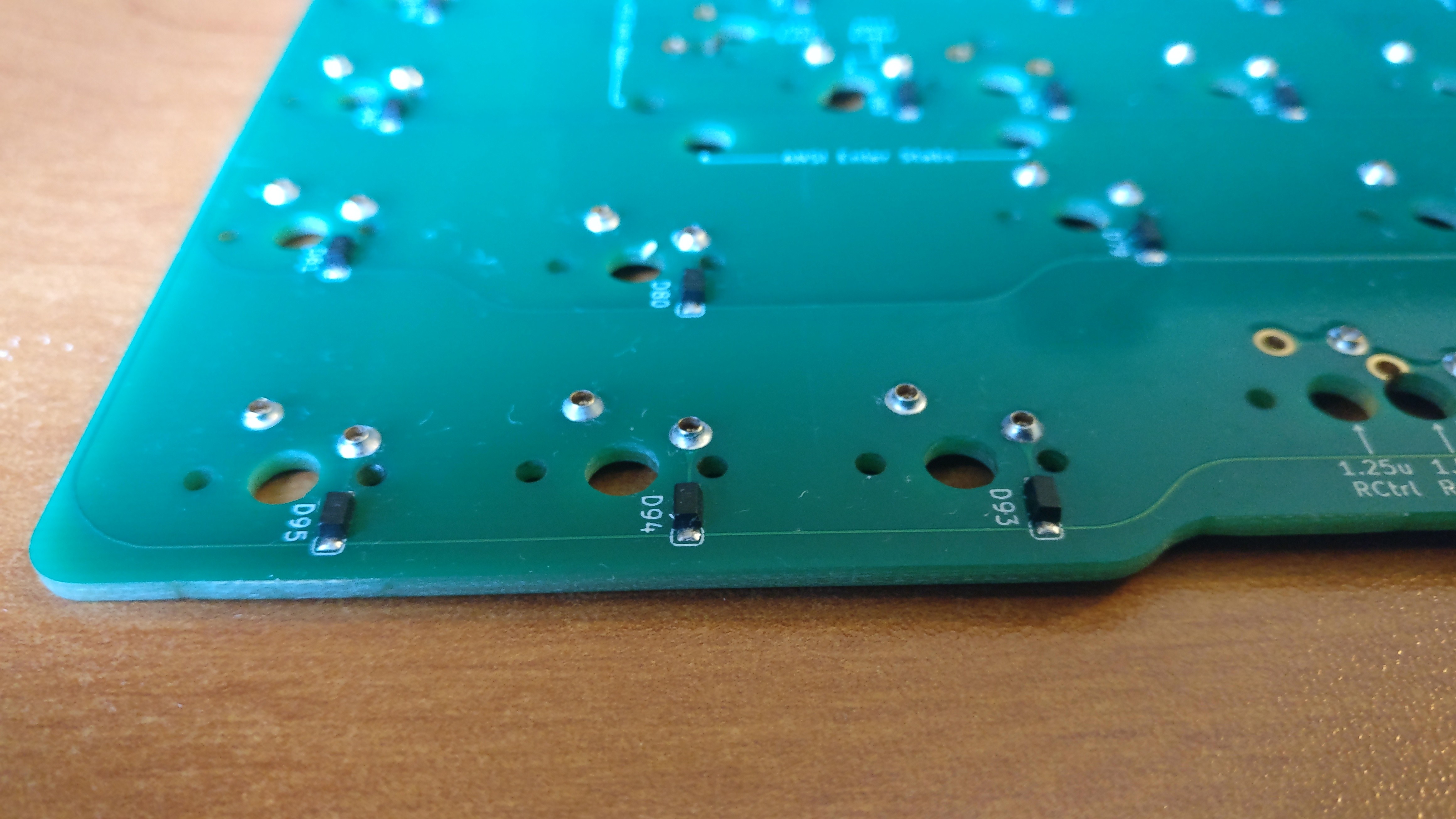
The pictures below does not make it justice as I am notoriously bad at using a camera.
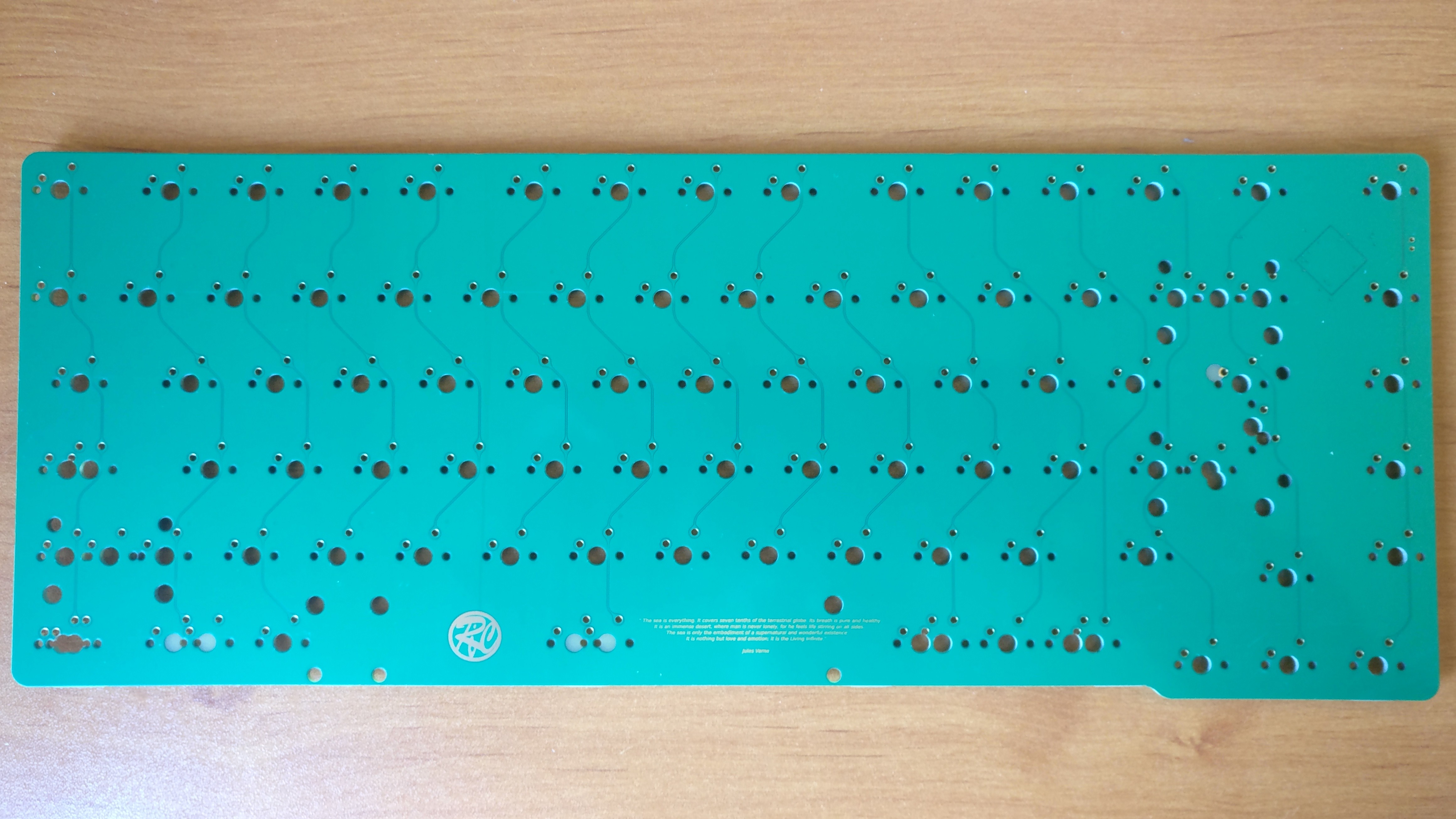
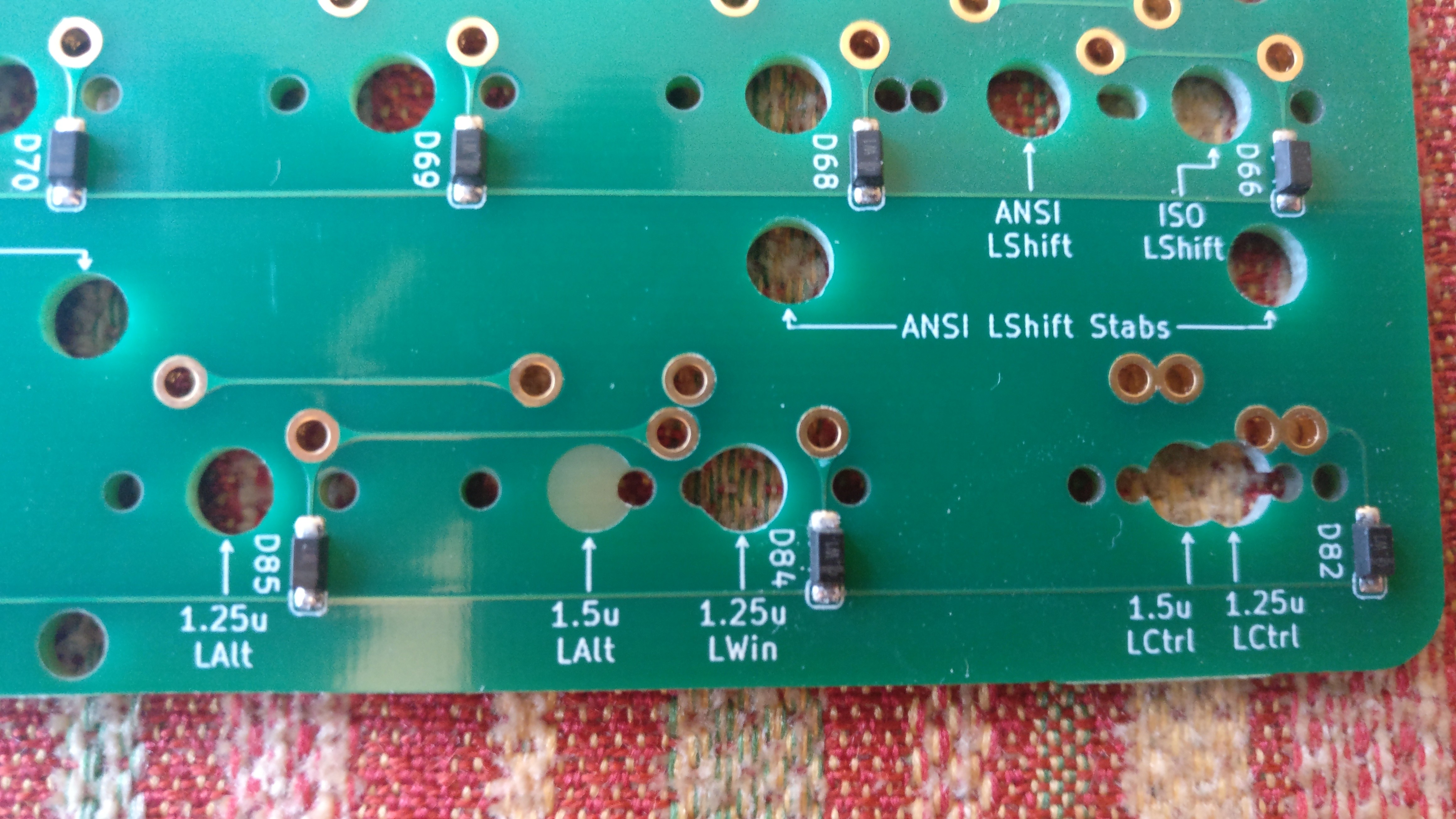
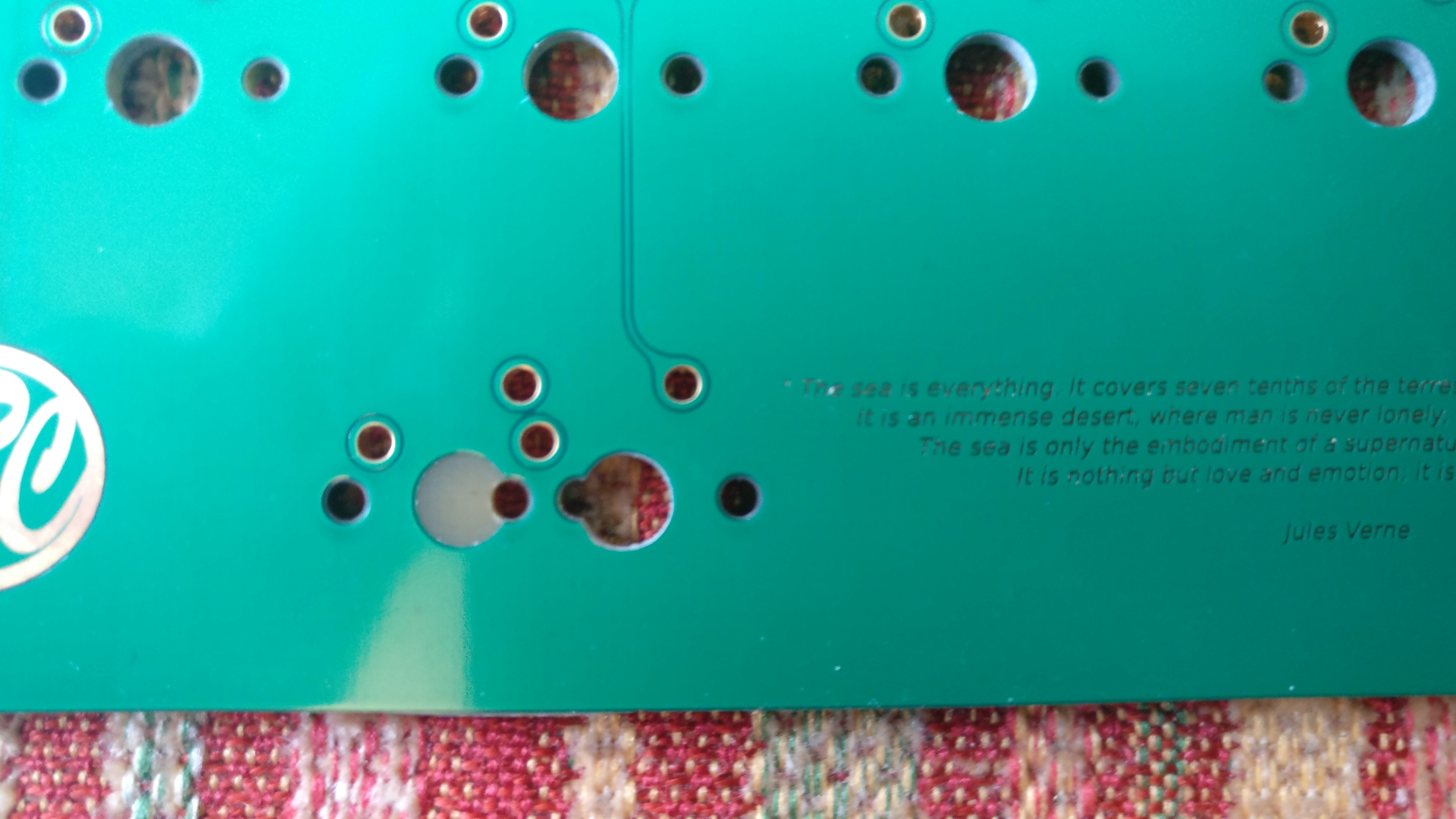
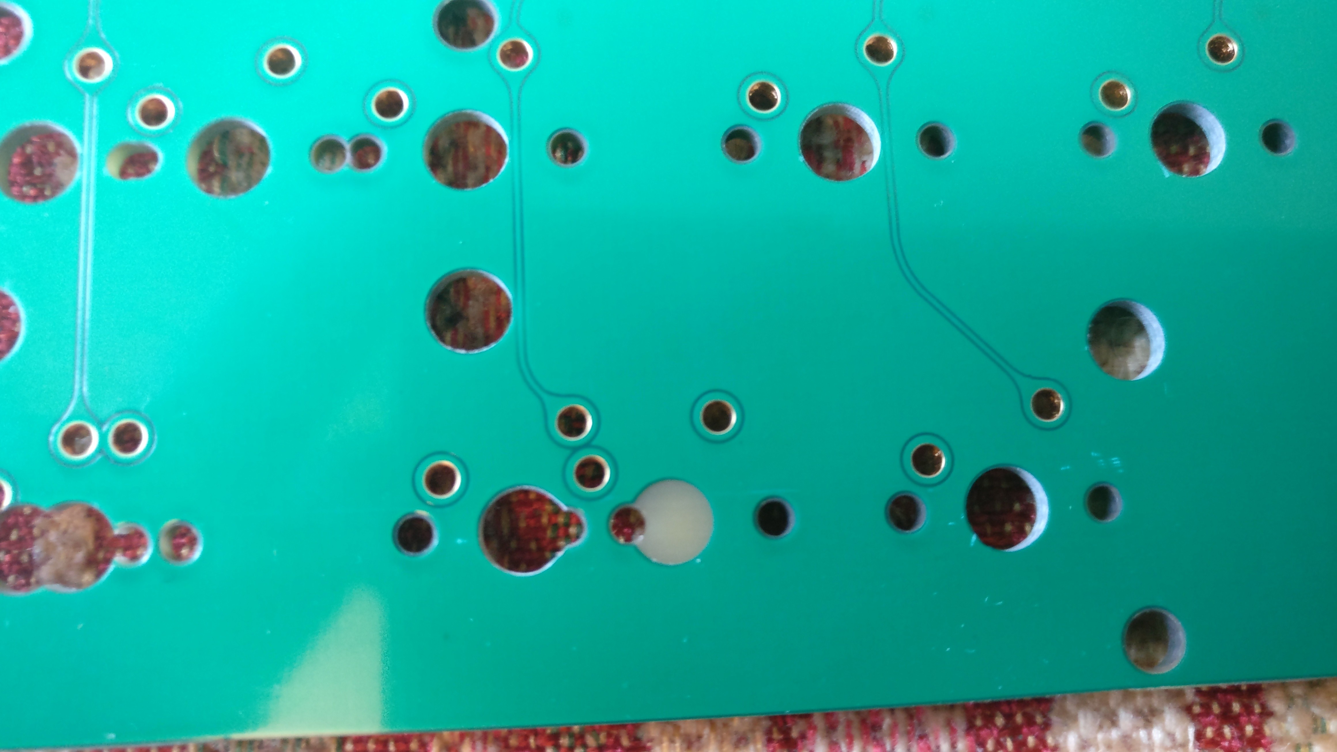
But if you look at the pictures closely you may notice a manufacturing problem…
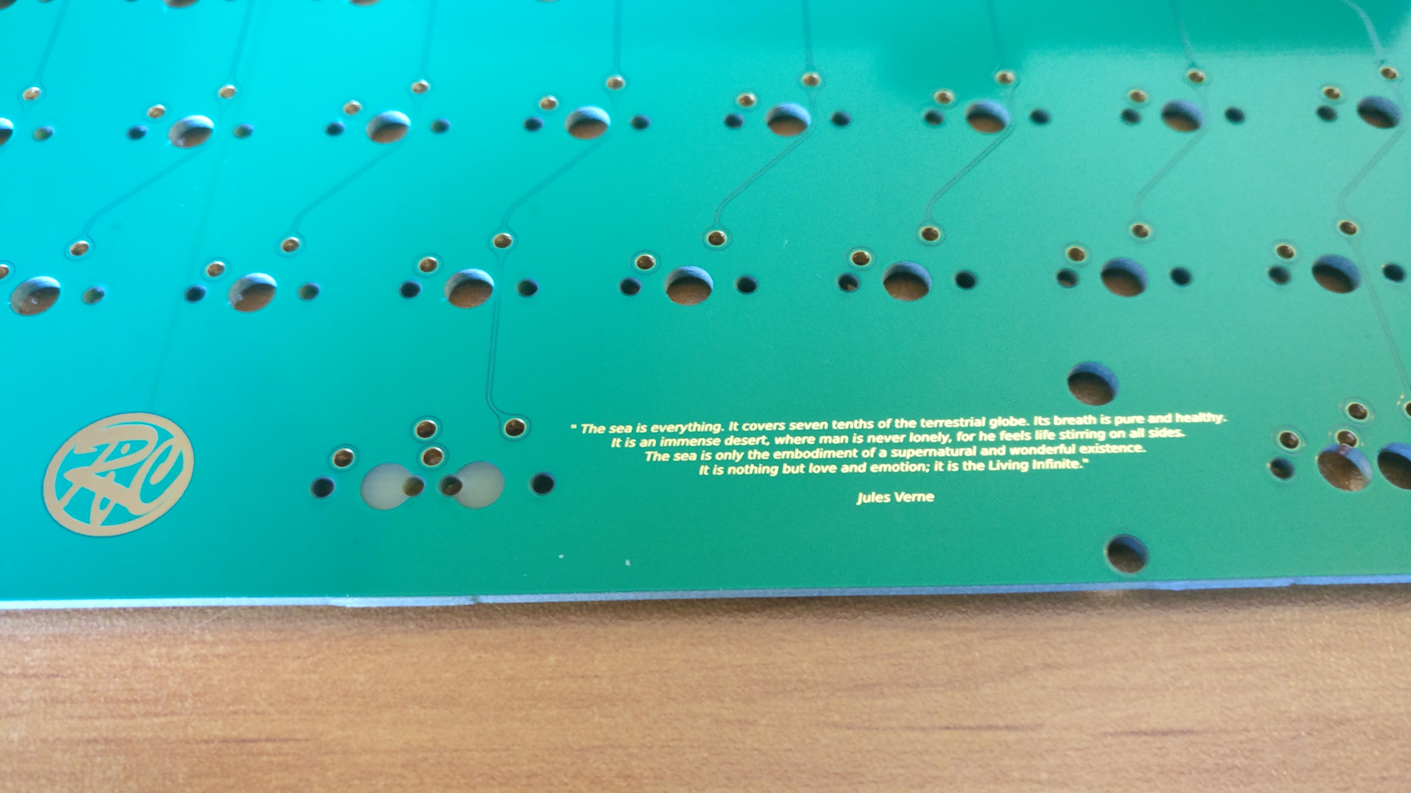
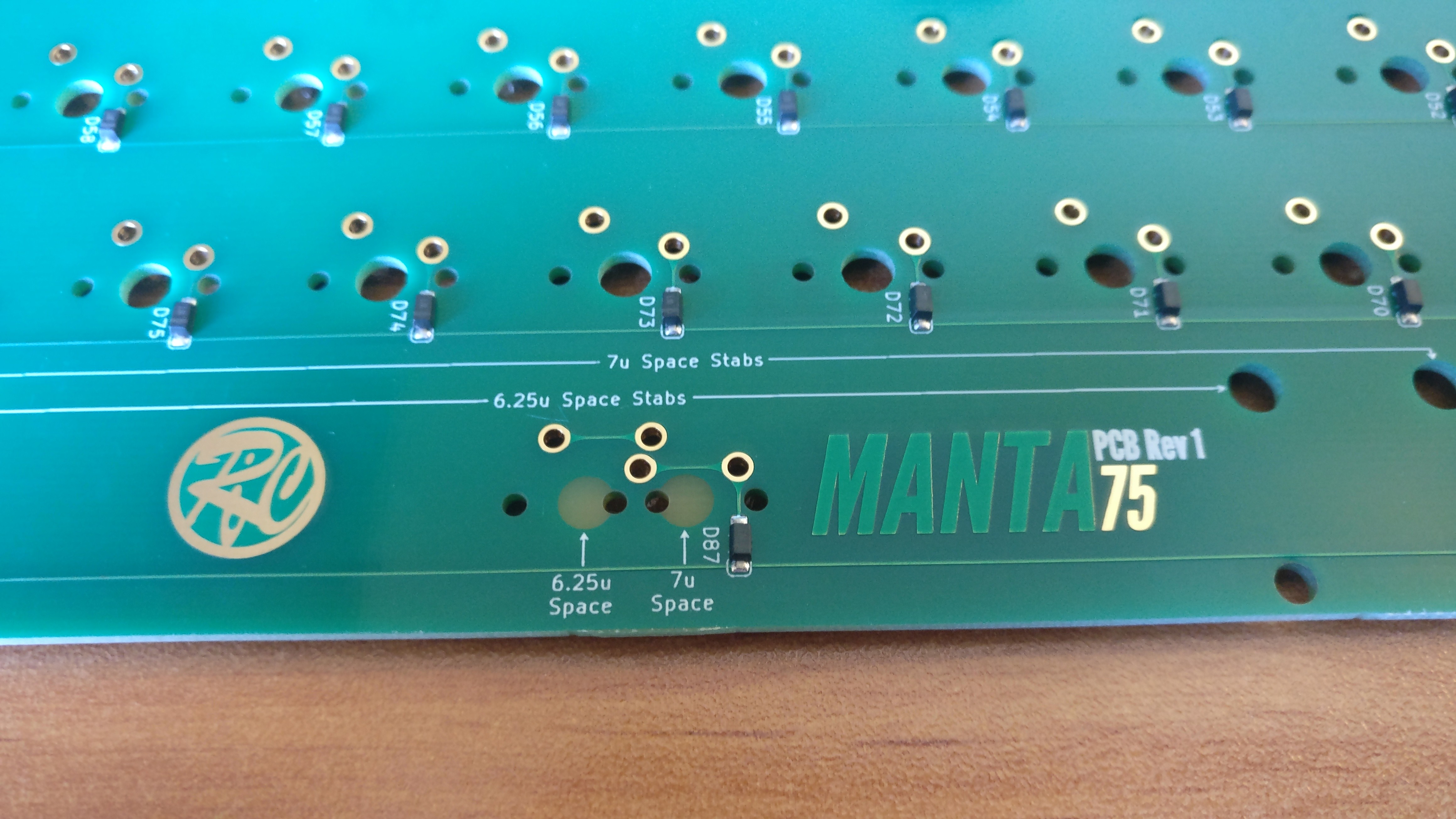
Yes, some NPTH holes have not been drilled 
JLCPCB has been very reactive, acknowleged their mistake, and I now have coupon code to remake those PCBs again at no cost.
On the bright side this gives me the chance to check if I did not made any mistake in the design 
… But I need to drill those holes myself.
At least the solder mask clearly indicate me hole perimeter, haha !
Maybe a task to do for this weekend.
3 Likes
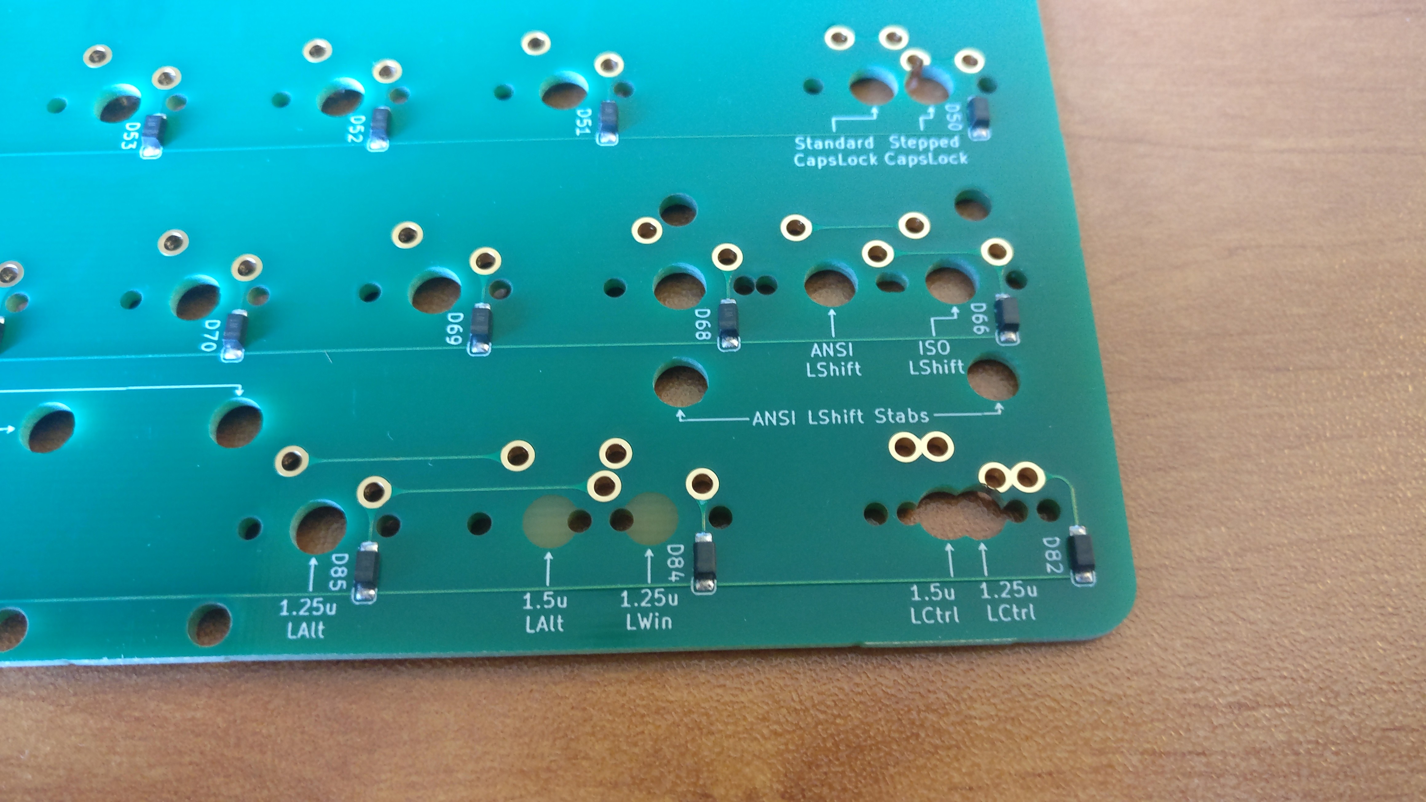
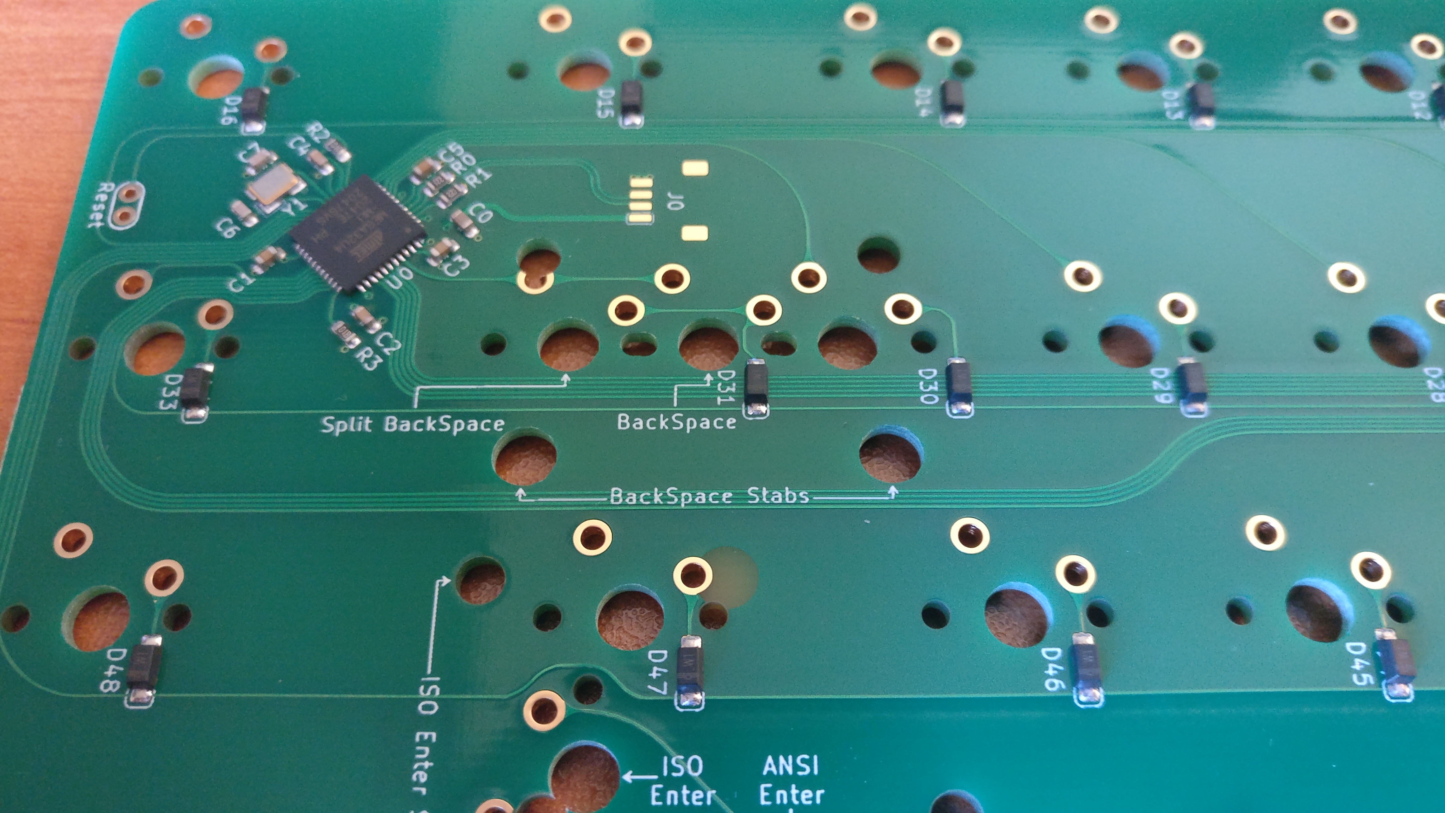
I love the solder mask graphics - but I really love the stab and bottom row labeling. So nice when it’s present…
2 Likes
I don’t think I’ve seen this on any other board but how is this not standard?? I feel like if I was paying $400+ for a keyboard this wouldn’t be unreasonable to expect as a standard for any PCB with anything other than a fixed layout. it would also be nice to see on standard 60% PCB’s as most of the bottom two rows are just swiss cheeze
1 Like
In fact Gondolindrim inspired me as it does that for all it’s PCBs.
@jshufelt can attest it is nice to have as he built an Austin some time ago (the PCB is designed by Gondo).
2 Likes
Had time to work on the project this weekend.
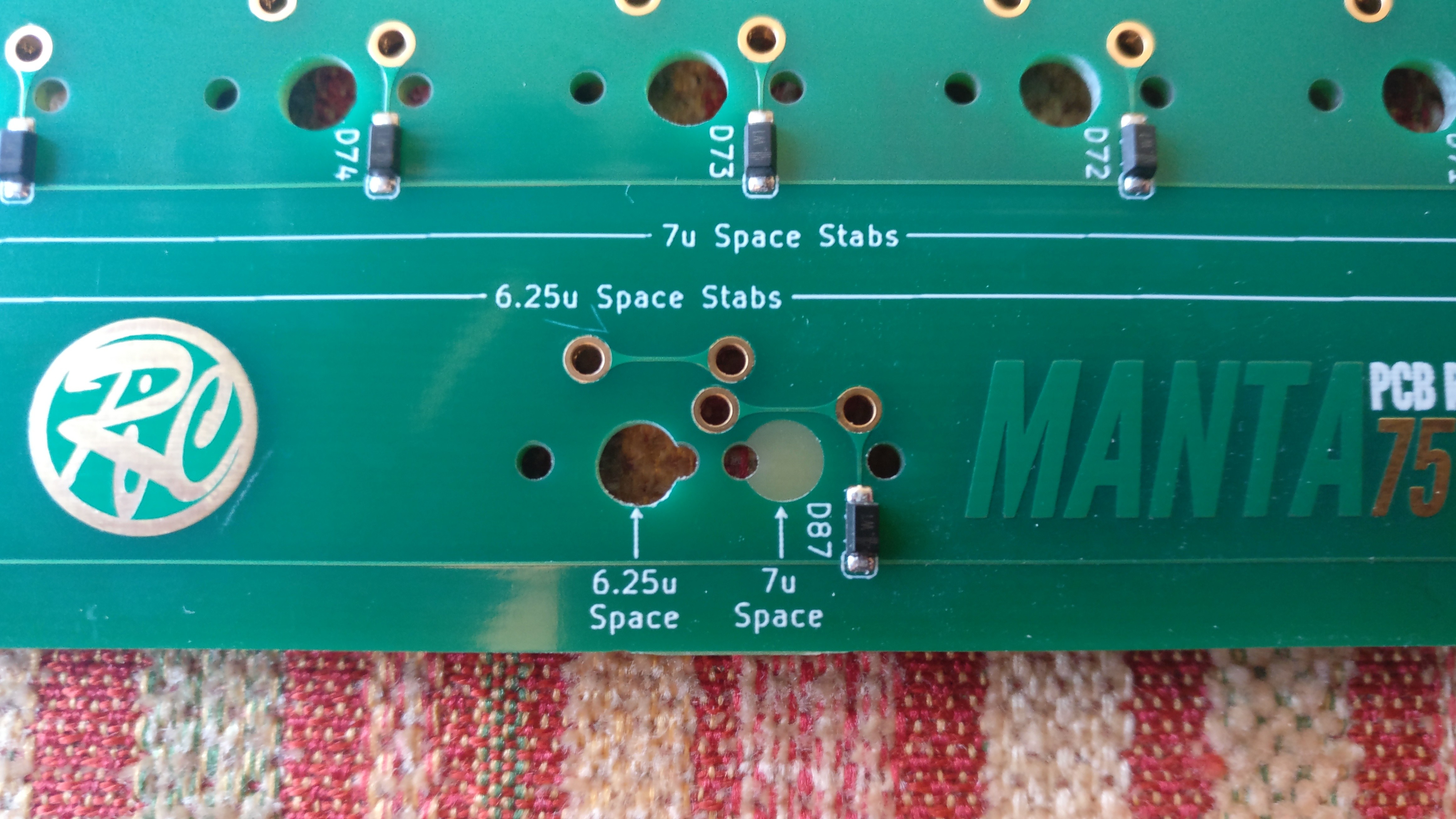
First goal, drill those holes that were erronously not drilled by the PCB manufacturer.
They were five not drilled but I only needed to manually drill two to have a PCB that support my test laylout: 6.25u space key and 1.25u Lwin.
Time to use the Dremel and the files.
I first drilled a small 0.8mm diameter hole as centered as possible, then used a 3mm diameter bit.
Finished with a small round file up to where the soldermask is starting.
I’m happy with the results 
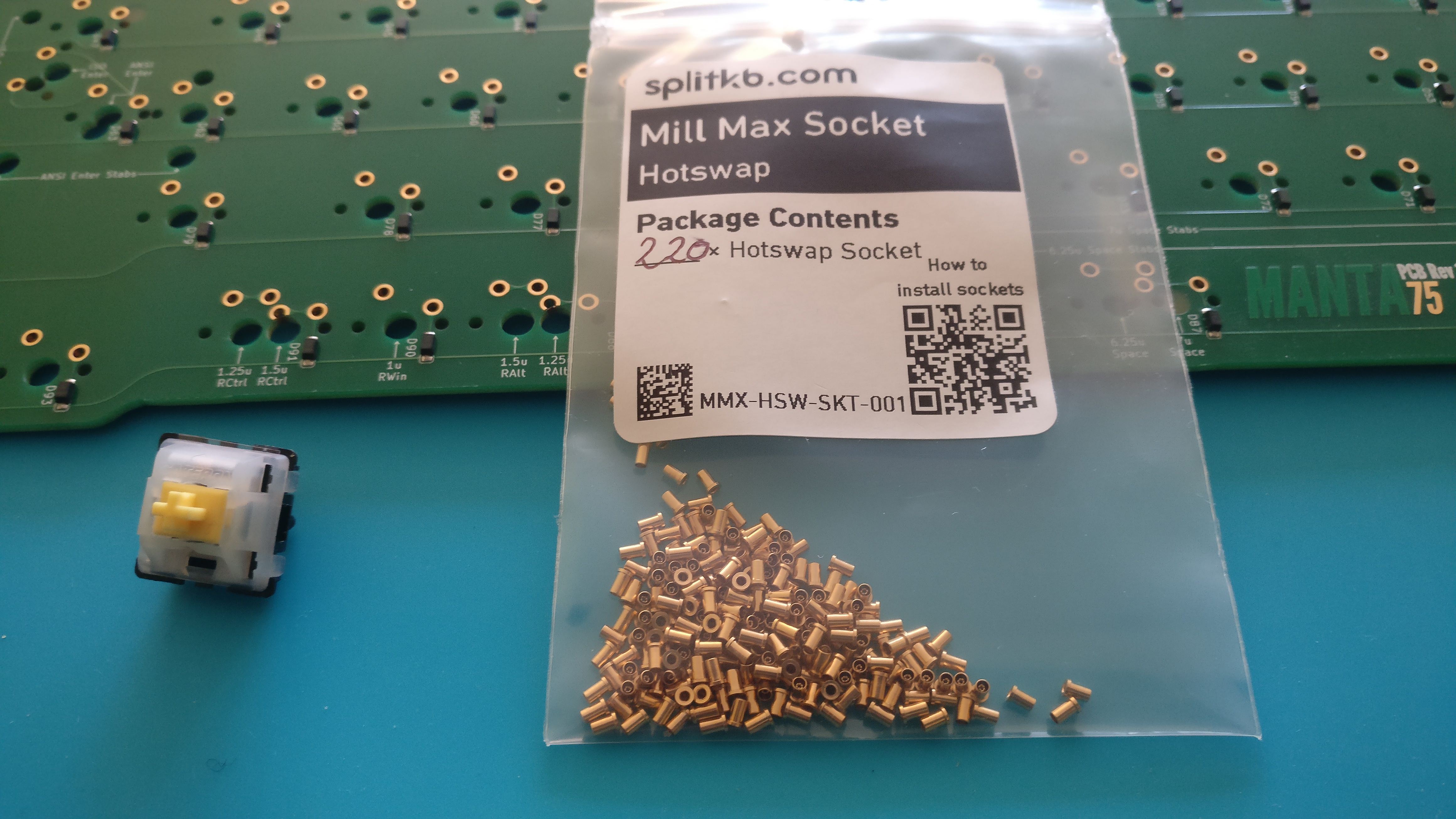
Then in order to start my plate design experiment I needed to make the PCB hotswap (don’t want to solder switches just for testing stuff) so I millmaxed it.
And boy this process is even worse than soldering SMD 323 diodes by hand
A few times I soldered the switch pin with the millmax socket and had to desolder the whole thing in order to put a fresh millmax socket … and most of the time the remaining solder in the hole makes inserting the new socket a challenge.
I’m not sure I will do that again in the future.
But hey in the end it is done and it works well.
I may next talk about the switch plate experiment, be patient
6 Likes
I may have time to talk about plate design and experiment today after all, so let’s get to it.
WARNING: this will be a long post.
The Winghead had a leaf spring design, witch I think was good to isolate vibration from the plate to the case. Another benefit is supposed to add flex to the typing experience but as my plate was made in brass it was quite stiff. Still it is nice (love stiff plates) but not what I had hoped, @Manofinterests told me it would be stiff (experience matters) and he was right.
I should have done plate simulation under Fusion 360, but thought it was not necessary to learn how to do it and I was wrong. Not this time, you will find proper simulations below
I knew already I had to make my leaves much longer than in the Winghead to have flex, and made different designs.
Here are two of them that I didn’t selected as viable candidate.
Side leaf springs:
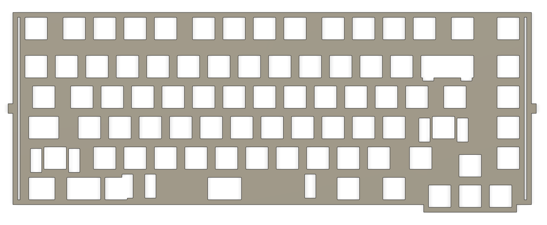
This one gave very good simulation results (most homogenous flex across the plate) but I was worried about fixing the plate with only two screws at the middle of the leaves.
PCBs and plates often come warped, and I was not sure only two fixation points would be enough to straigthen all that.
Diamond leaf springs:
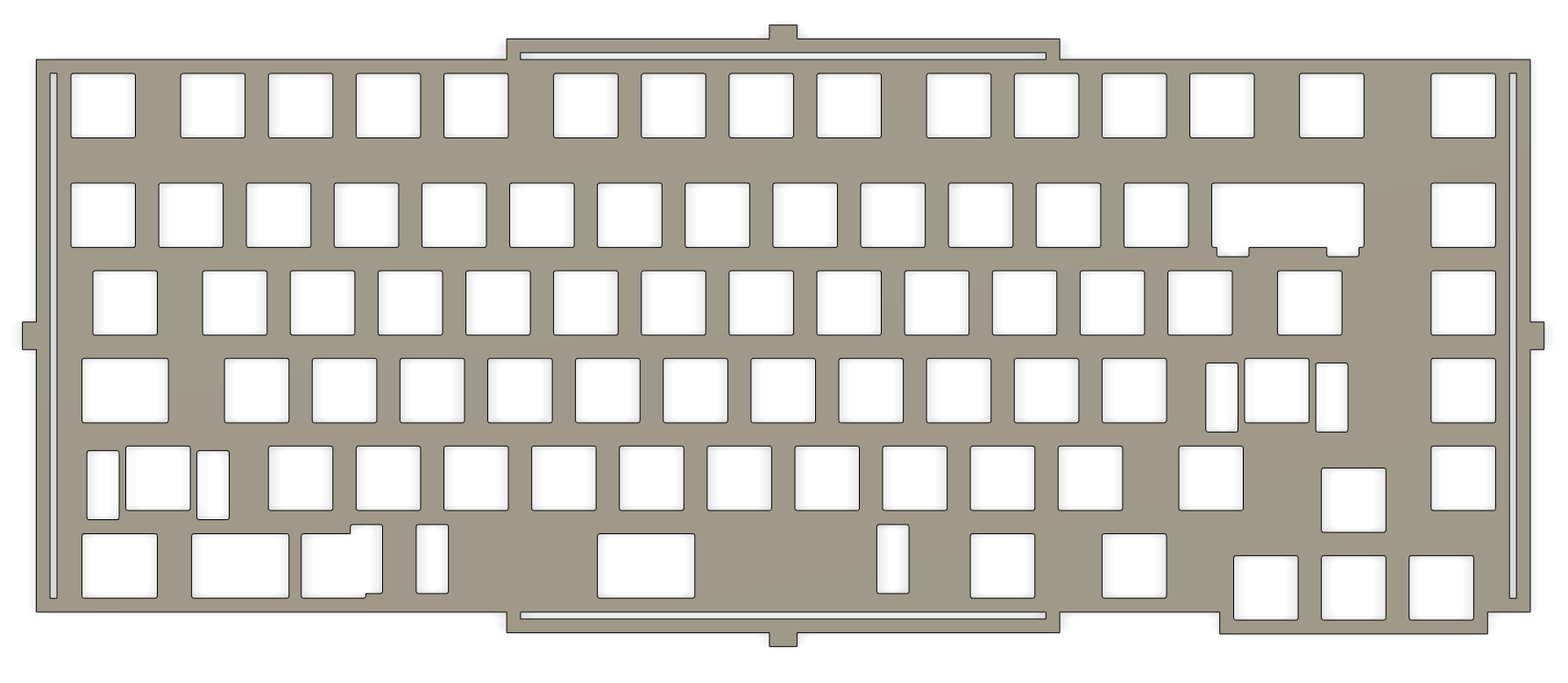
Good simulation results and now 4 fixation points that should alleviate PCB/plate warping.
But I didn’t like the side leaves as it would force me the make thick side bezels and add too much constraints in case design.
I may have thick bezels in the end but at least the leaves will not be in the way for the case design.
The selected one has been the top/bottom leaf spring design:
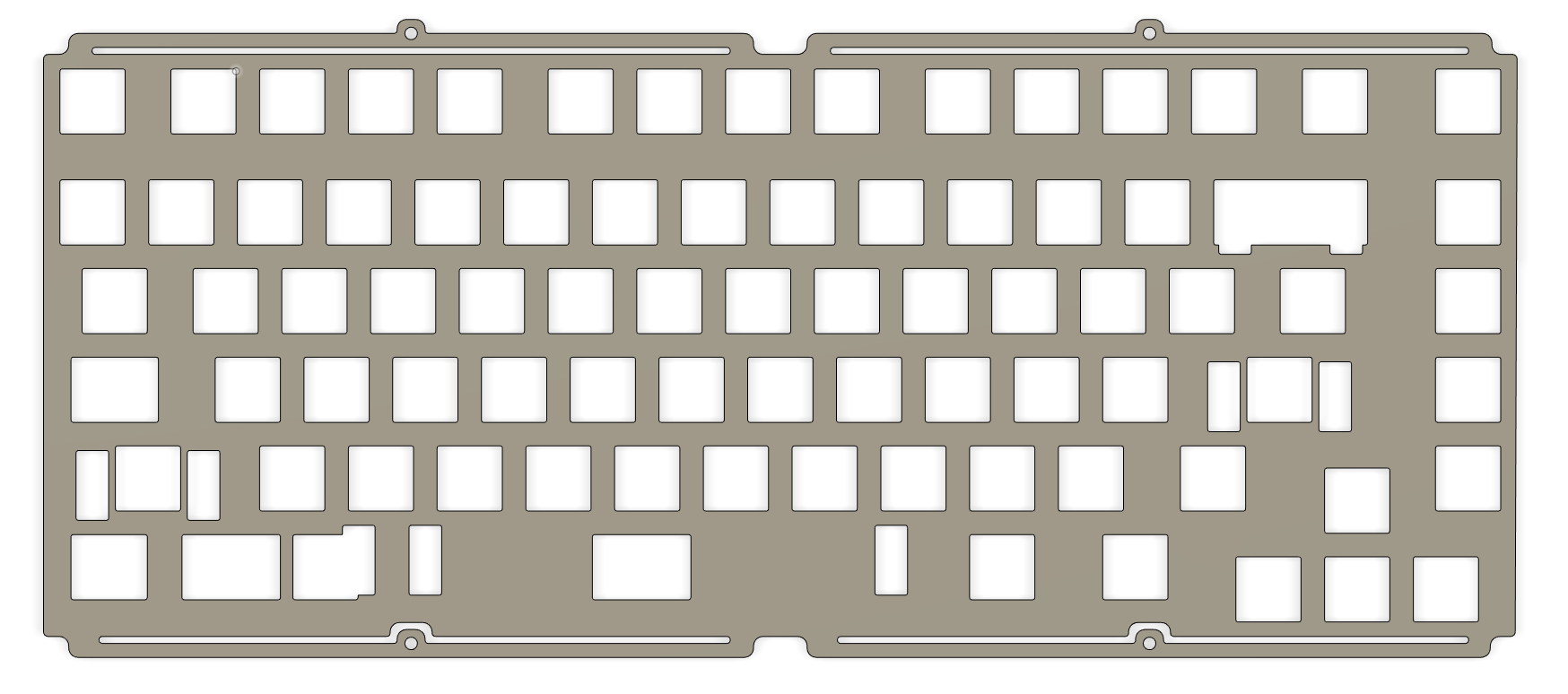
Why not more leaves ?
Because simulation showed that the more leaves you add, the more uneven the flex is on the plate.
So I added the minimum that I thought was necessary to have the best flex uniformity and solid case attachment. Following simulations will better help understand the problem.
I didn’t used this model as is for the simulation.
To better simulate how it would work in practice I have to mimick when the plate is fully assembled with switches and PCB. Make a real simulation with all switches and so on would be too much difficult.
So I made a few modifications so that everything but the leaves are very stiff.
Also added a few surfaces areas on the plate to be able to study forces at different places on the plate.
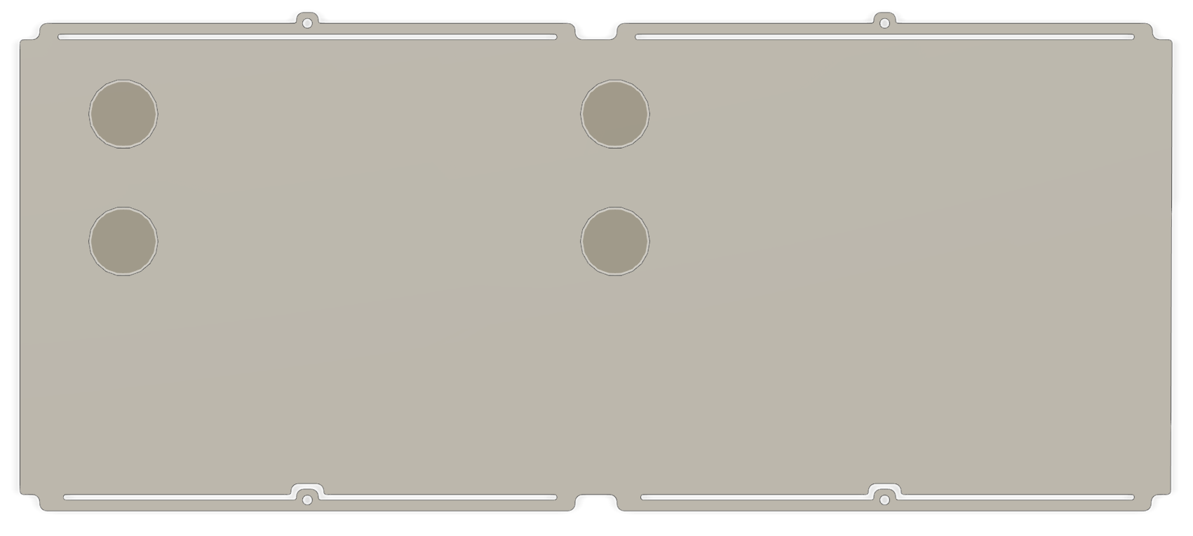
Tests have been conducted by applying a 20N force (around 200g) at these four locations.
Selected material is aluminium (6061 if I remember well), gravity is not taken into account.
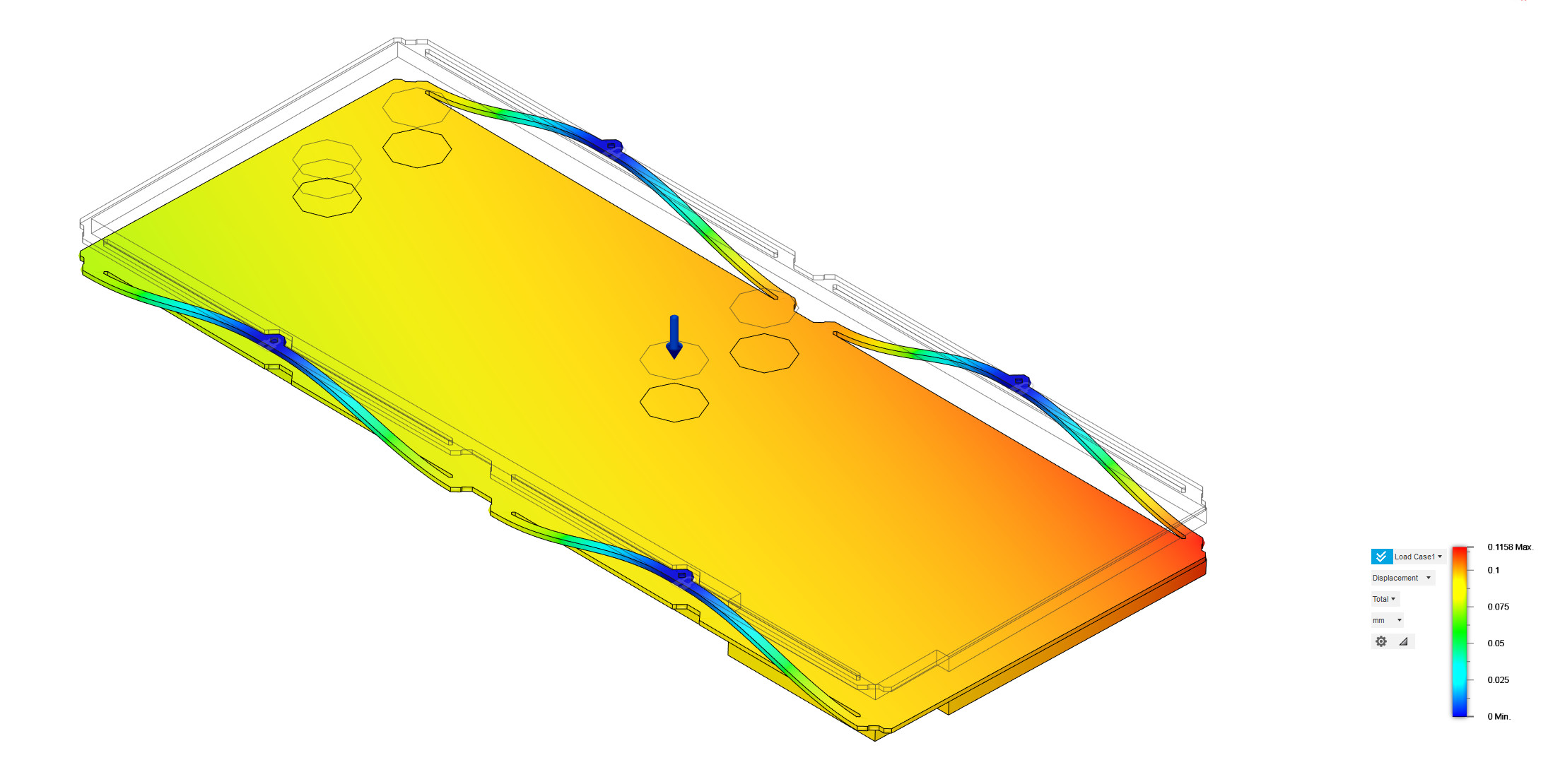
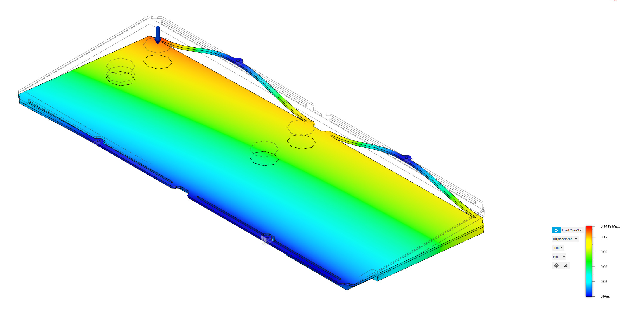
Here are 3 of the 4 simulation results, showing displacements.
Center press:
Center left Press:
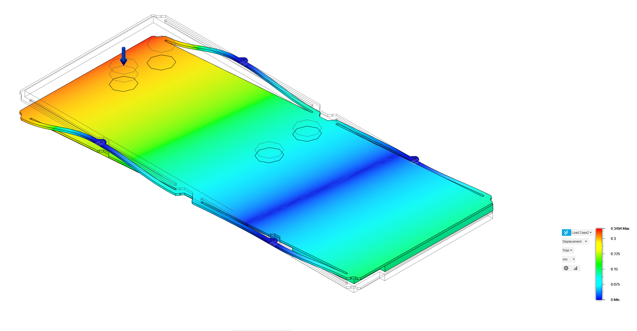
Top left Press:
Top center is very similar than center left so is not included.
Displacement is uneven depending on where you apply force:
- 0.12mm for center.
- 0.14mm for top left.
- 0.35mm for center left.
Had better results with the two leaves approach (didn’t kept the results, sorry).
Looks like the more you add leaves the stiffier it gets when you go to the center of the plate.
4 leaves looks to be a good middle ground, now only real life experiments will give the answer.
Time to put everything together for a real test!
LaserBoost cut me a test plate in 5052 aluminium:
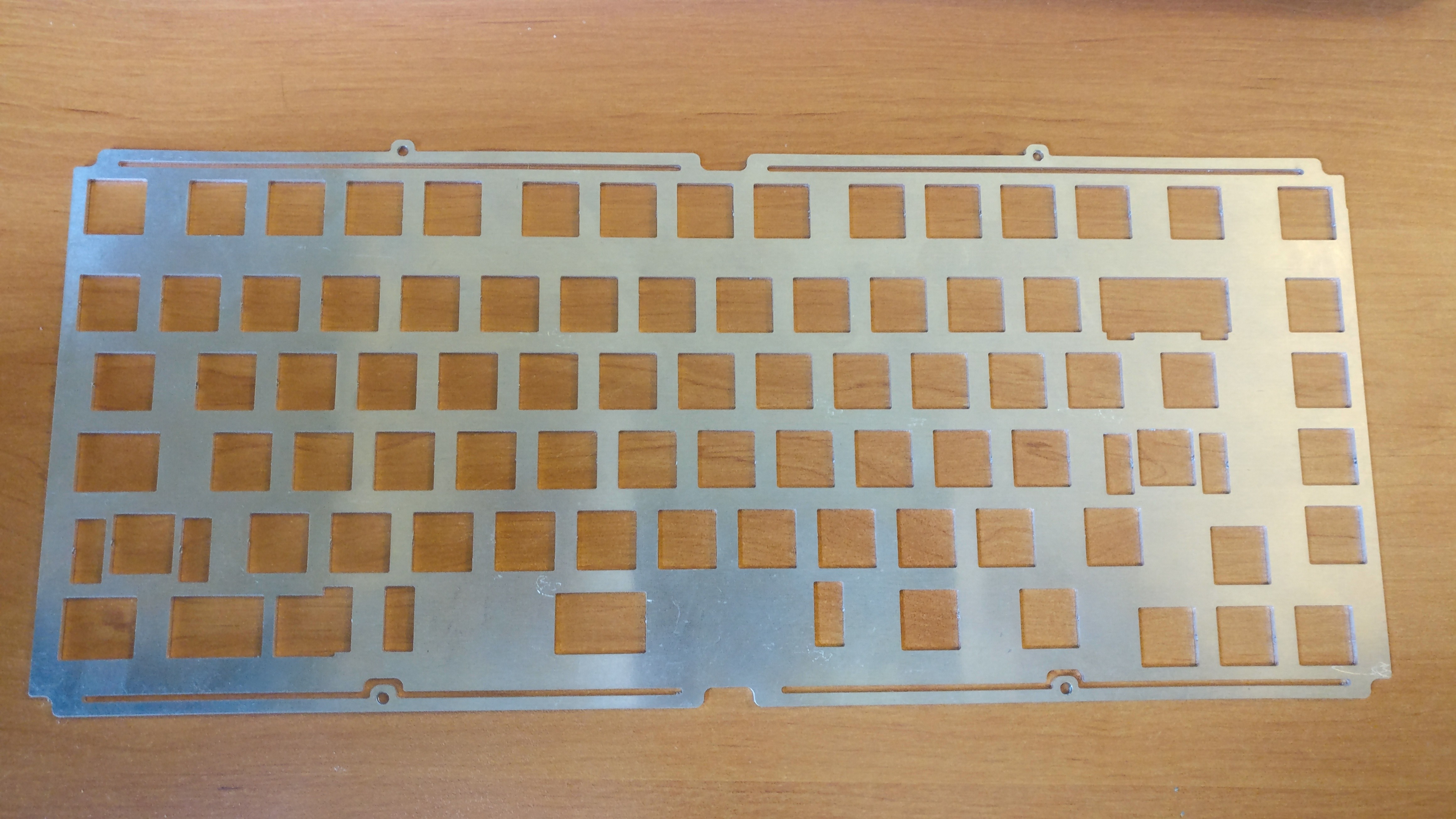
And the pcb.
See the warping ?
Will it reduce when assembled ?
First tested the plate alone with a wood frame:
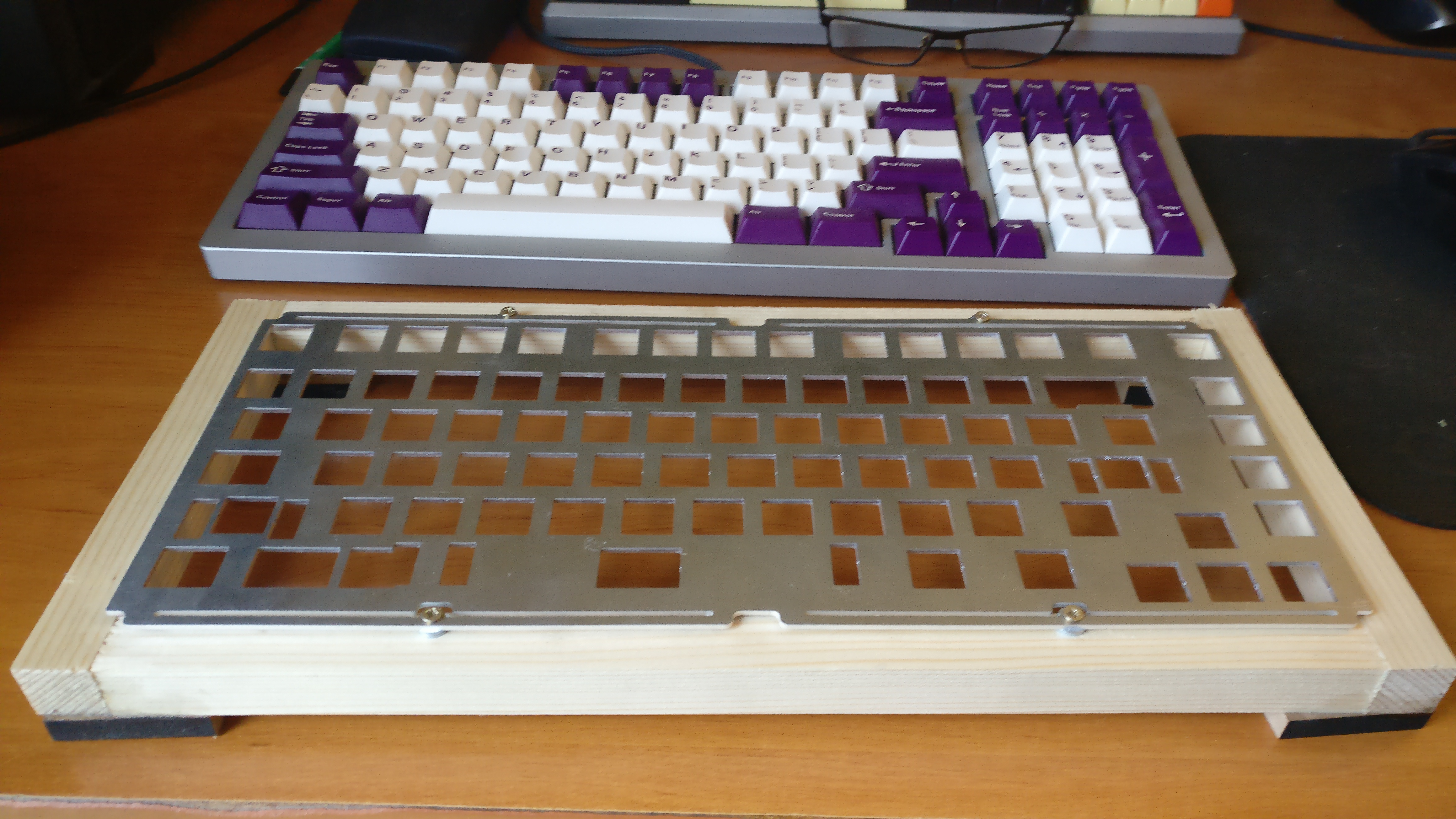
And the results to the feel is not at all what the simulation gave me…
But this is because the whole plate is bowing, not only the leaves.
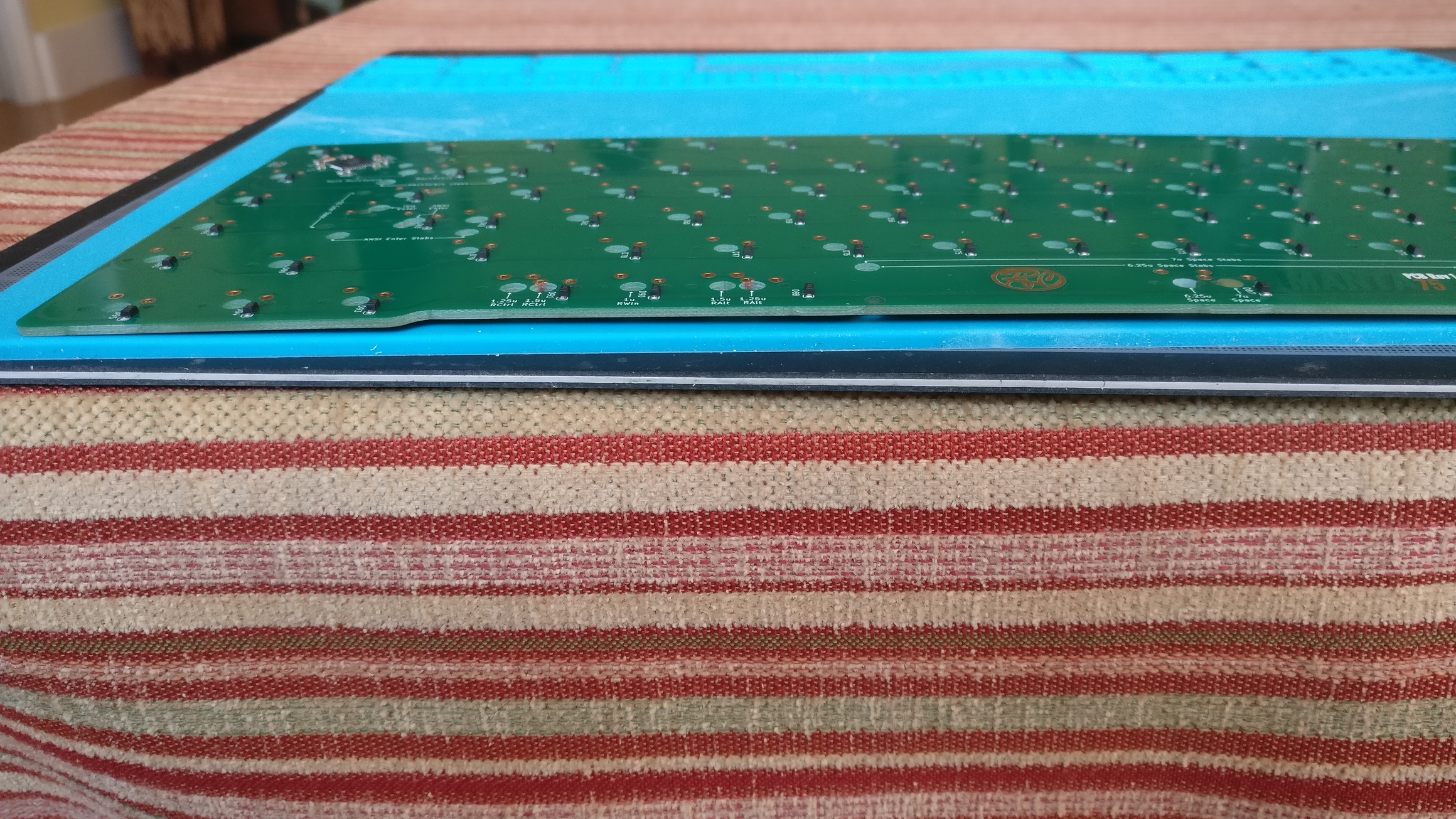
Everything assembled together:
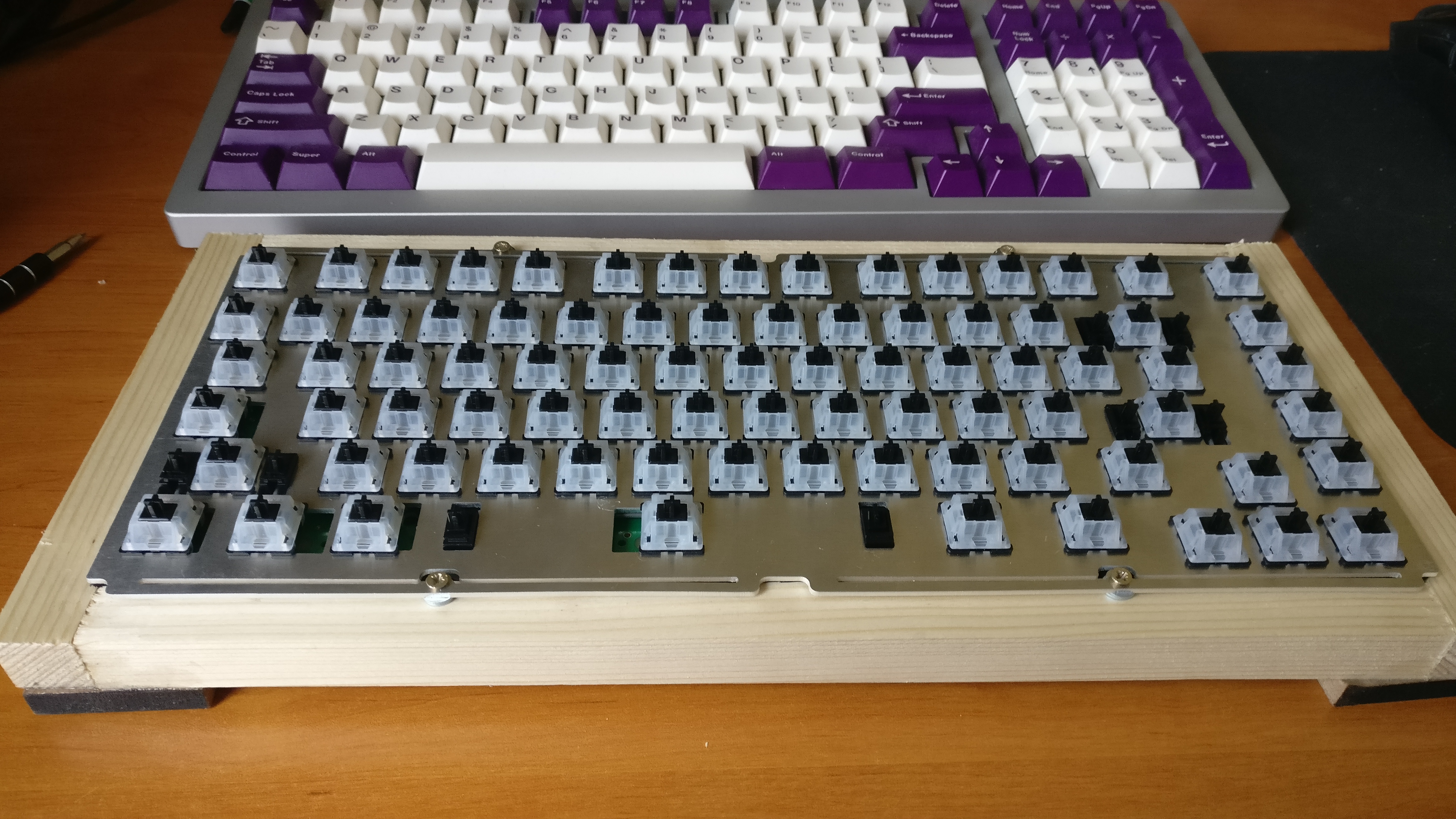
The warping has been significatively been reduced by the assembly and the four fixation points are doing a good enough job.
And the experience matches what I had simulated, great!
But how does it feel?
I don’t have spare keycaps, but already can give a few feedbacks.
You can see the plate move when typing, never typed on something that soft before, I like it.
And the unevenness of flex is hardly noticable to me, so good point.
Also the plate does not bow anymore when applying force, only the leaves are deformed.
And its bouncy!
@Wilba explained for it’s Thermal that the leaves where allowing the plate to vibrate, it is exactly that
Not sure if it is my taste, we’ll see…
And there is maybe a way to dampen the vibrating factor and improve flex uniformity at the same time.
But no more time to test that now.
See you!
10 Likes
Long time no see!
I waited a long time for components to solder the Universal C3 USB daugherboards.
You may know that STM32 MCUs are pretty much out of stock everywere, and this also more or less the case for the Texas Instruments ESD protection chip used in AI03 design.
I had to rely on a different reference part from the same company, and compare the contents of the two datasheet documents to ensure it what doing the same thing…
Also made a JST cable … using incompatible connectors with a wrong reference (a mistake of the vendor). So ordered pre-made Qwiic cables while waiting for the correct connector reference…
But now I have everything, no more excuse to check if everything is working as intented!
First was the soldering of the C3 Universal USB daughterboard, I made 2 in a row.
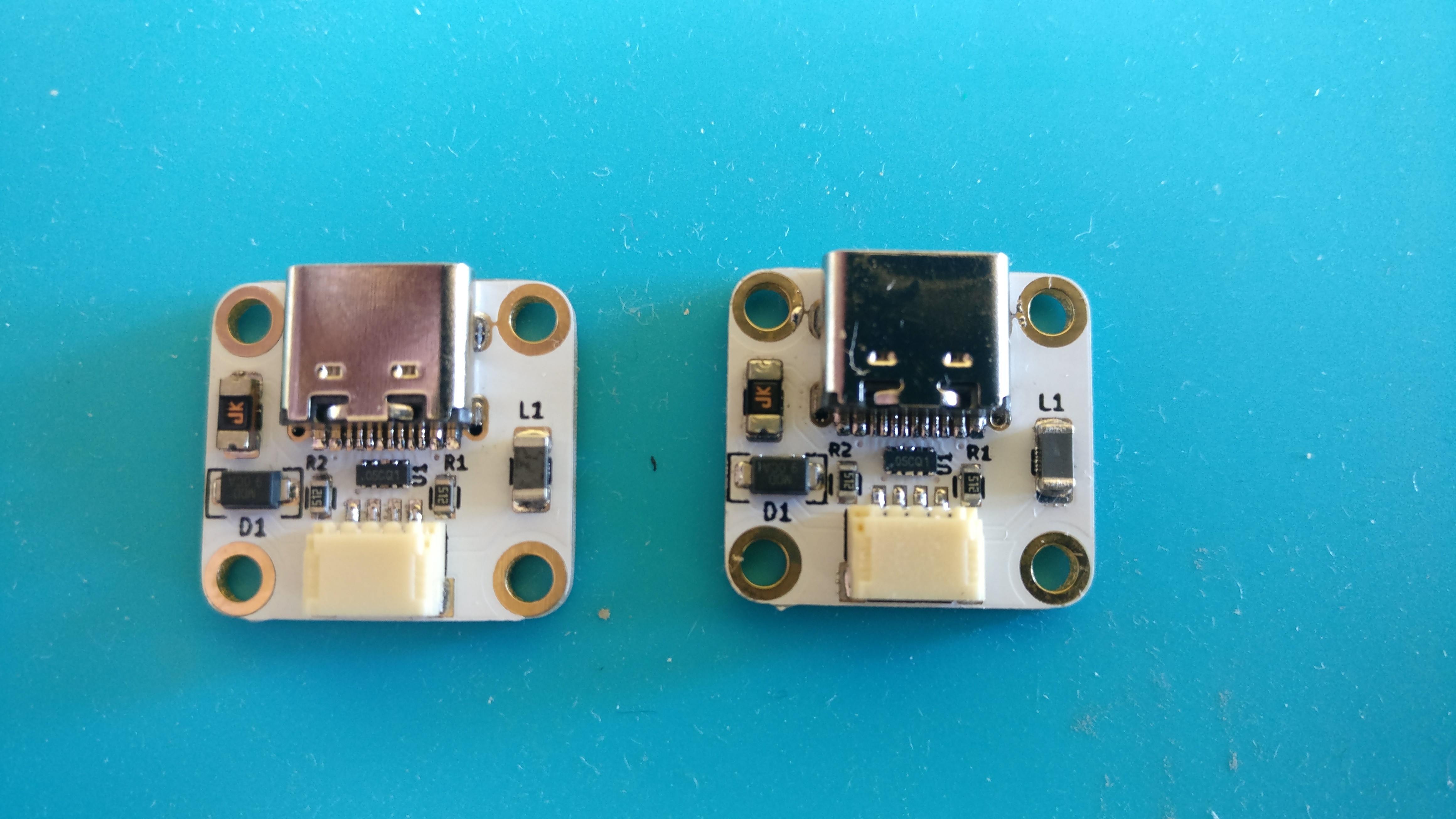

Not perfect for a first try, still need to cleanly solder the shield pins for example.
I will do probably much better for the future ones.
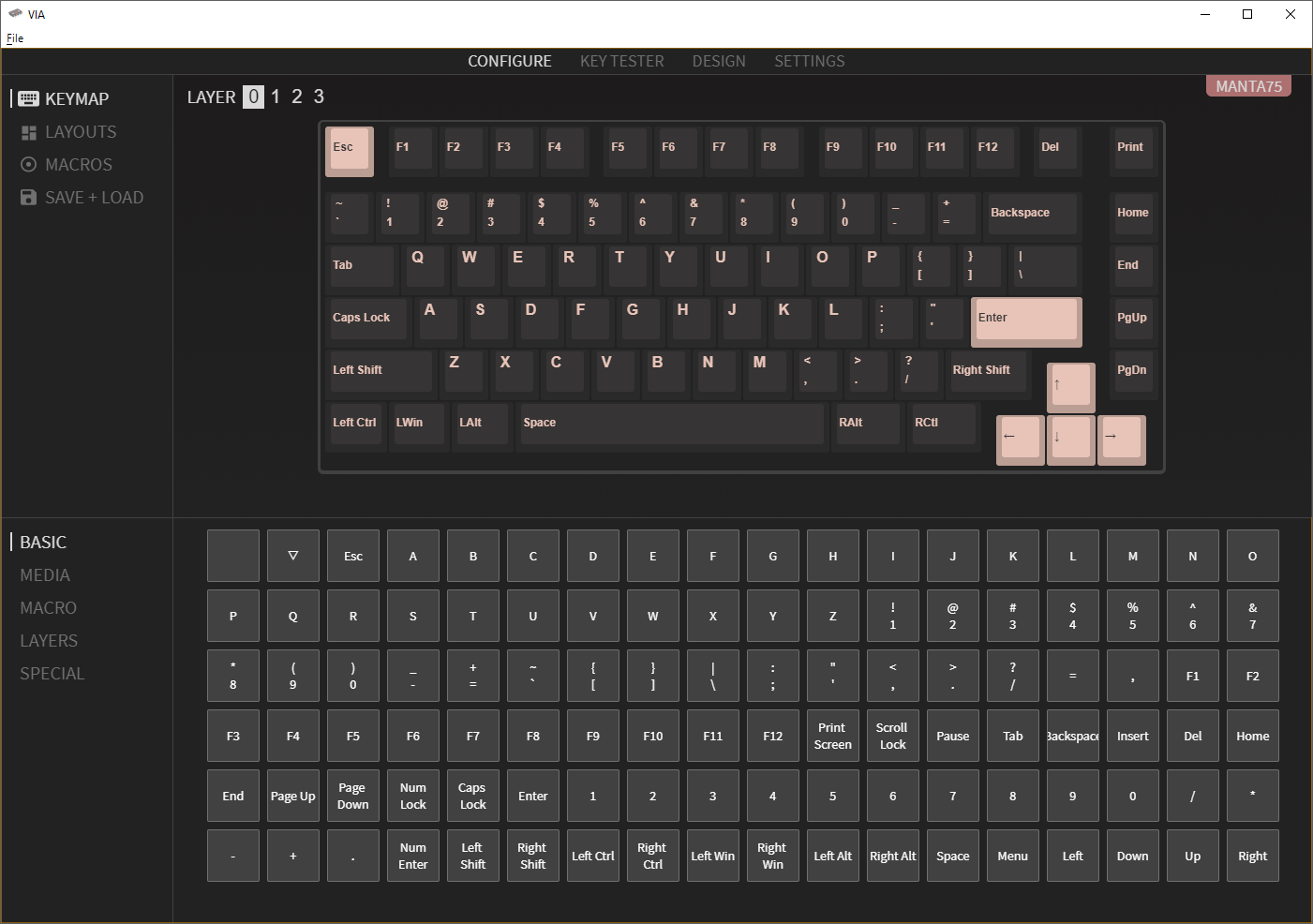
Then QMK firmware programming with VIA support was quickly made.
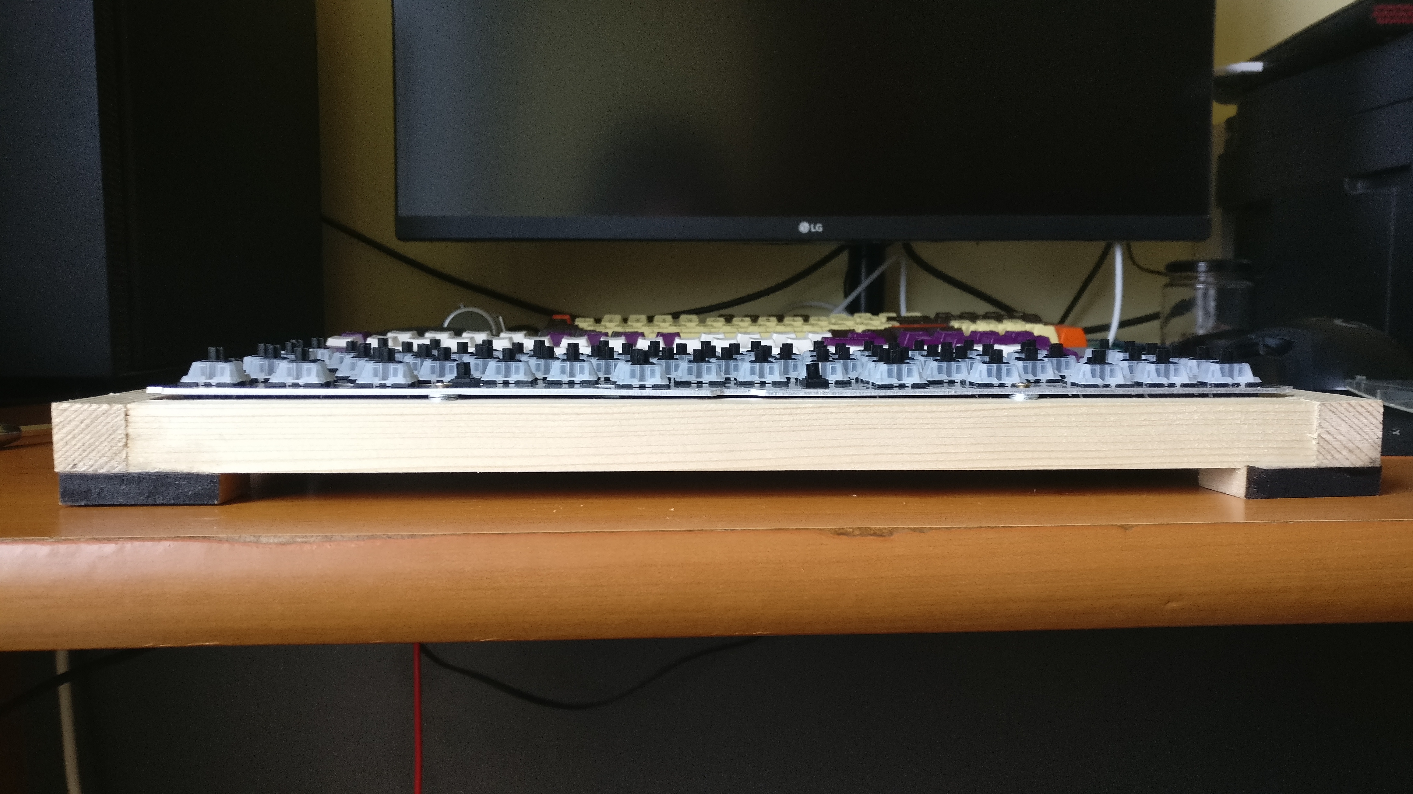
And last the test of the PCB, the one I had assembled previously with an aluminium plate and a wooden frame (with MT3 BOW keycaps that I had received not too long ago)
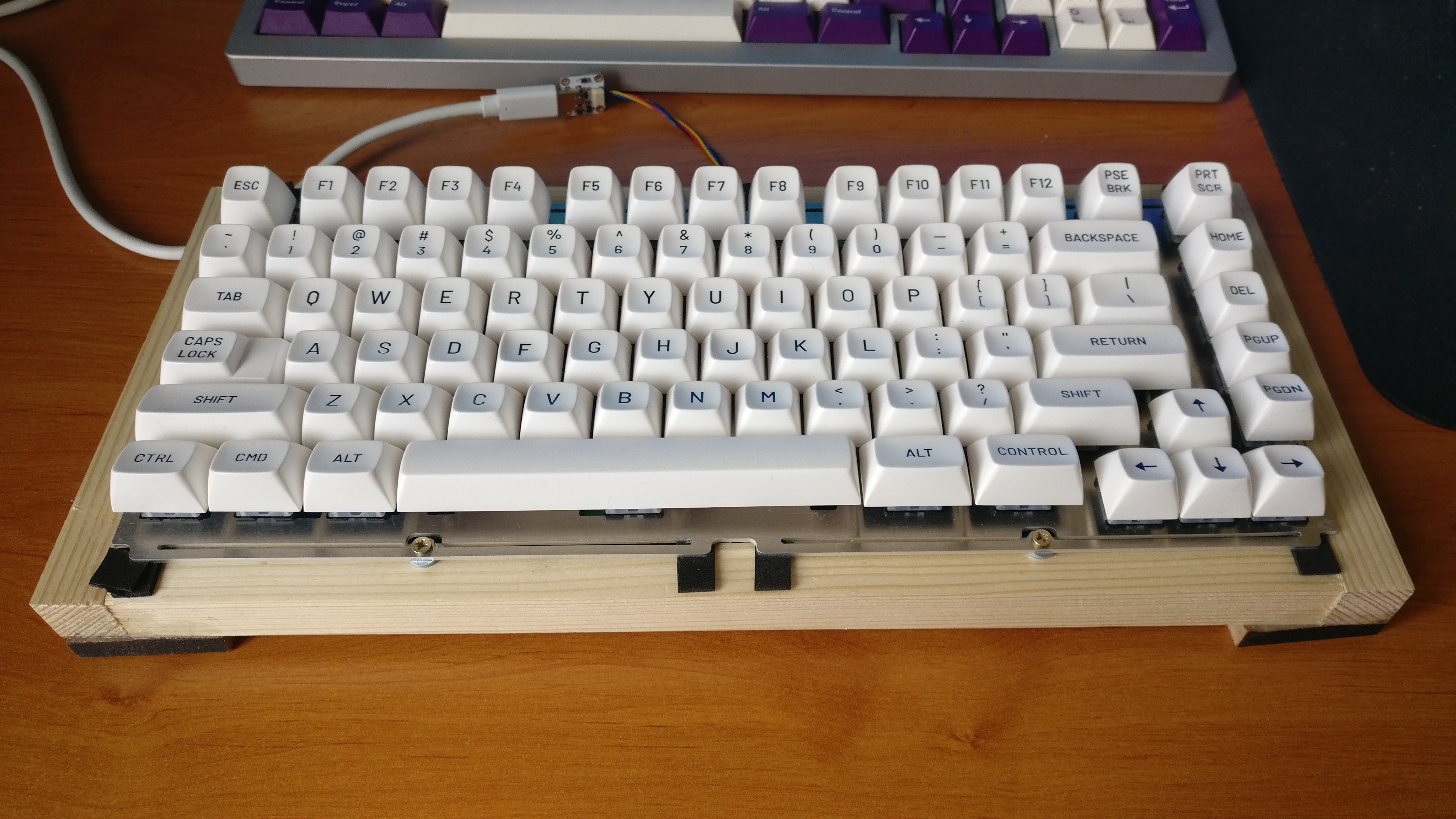
Verdict

Happy it went smoothly, was very soon greeted by the nice VIA menu.
You can see some black foam under the end of the plate leaves
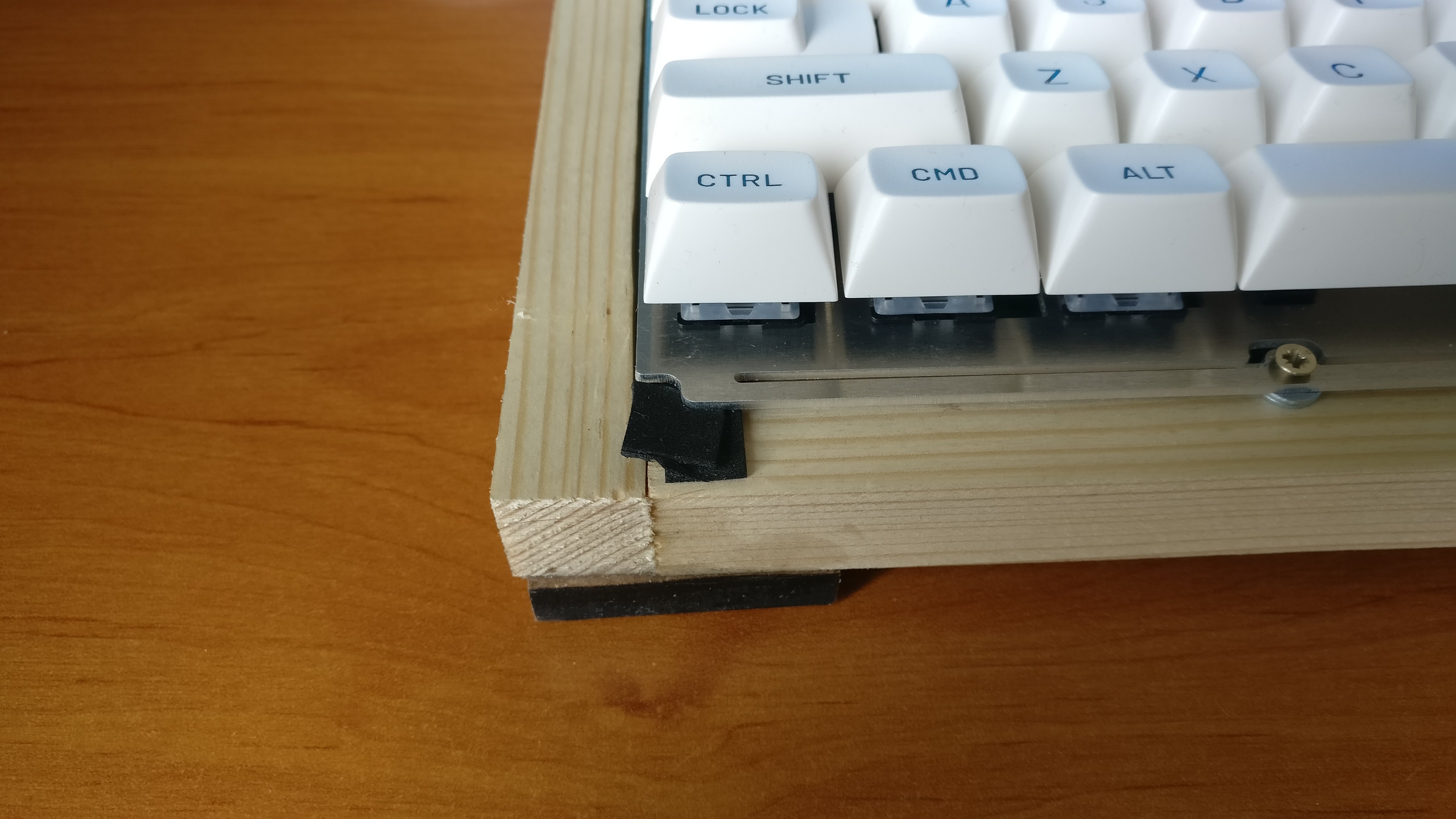
This was an experiment to reduce the bounce and add flex uniformity, it works really well!
Afterwards I discovered that the Thermal had more or less the same thing, same for Salvation and Thermal+, same for the Vanquish 65 (by Geon).
So I didn’t invent anything but I’m glad that the idea is not stupid at all 
See you!
9 Likes
Hello keeb lovers,
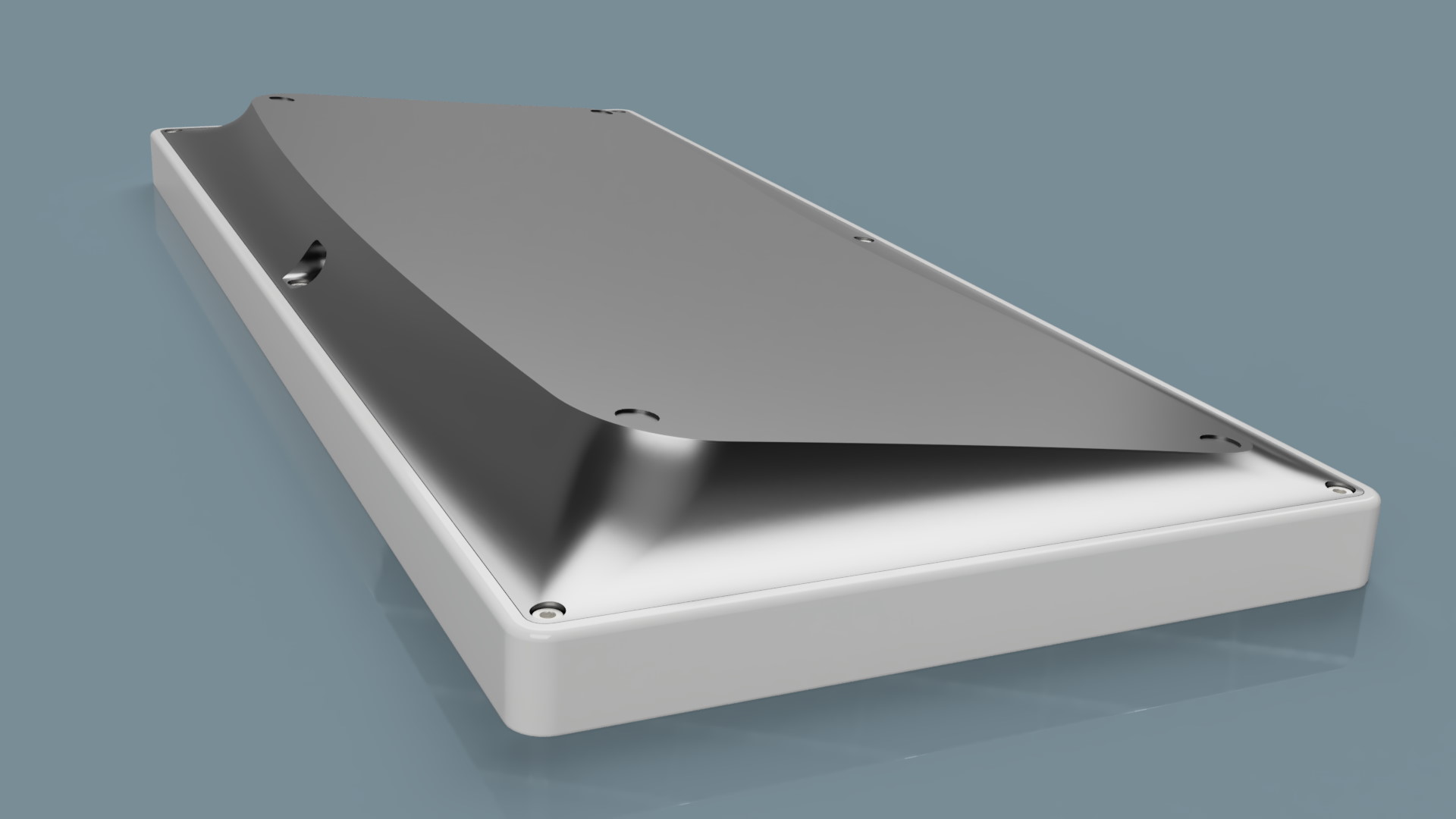
A little bit of news with the case design that is mostly done, lots of rendering images will follow in this thread. Sorry it took so long…
I took me quite a while, designing around a rectangle is surprisingly difficult due to all dimentional constraints that exist in a keyboard case.
I had several goals in mind:
- iterate and improve the existing Winghead design.
- take inspiration from other known designers.
Winhead design improvements have been:
- A higher plate to top case height, from 6 to 7 mm, as I found that SA keycaps were protruding a tad too much.
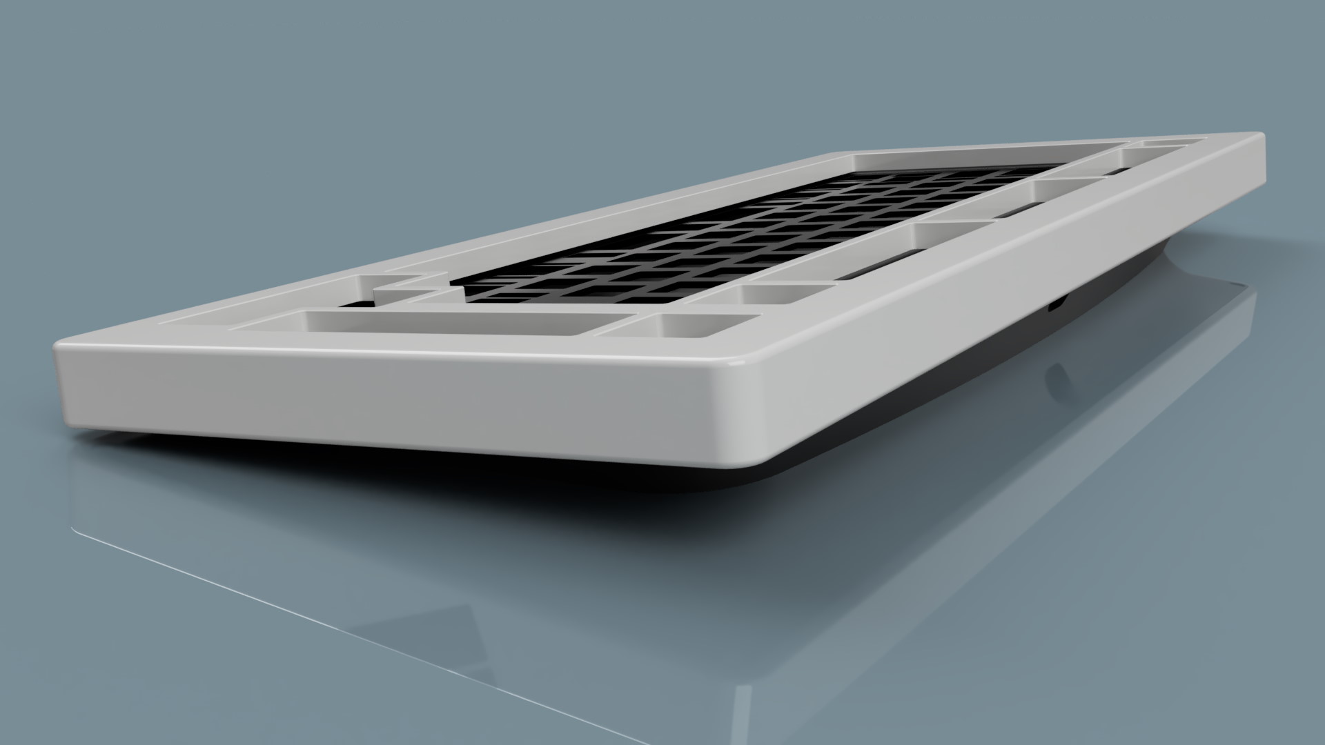
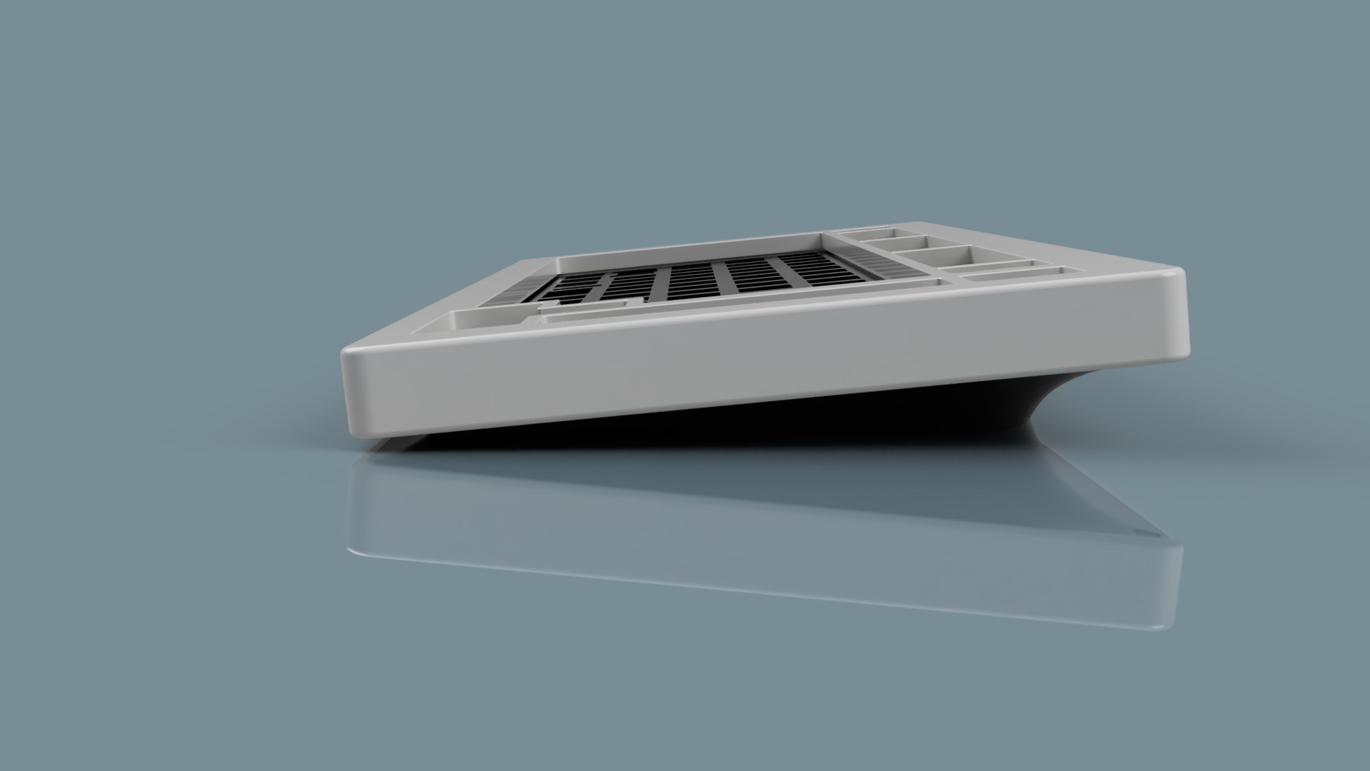
- Better defined curves for the case bottom, all ending at a zero degree angle to the start of the top piece.
- Accentuated bottom piece curvature to accentuate the floating impression of the top piece, this also had an effect of thicker bezels on the sides.
- Uniform bezel all around the keybaord of 15mm (love tthick bezels).
- Increased top/bottom pieces fitment tightness a tad bit (from 0.2mm to 0.15mm).
- Increased case angle from 5 to 5.5 degree, still pretty low for a comfy typing experience.
- Front height goes up to ~18.3mm (from ~17.3mm for the Winghead) due to higher plate to top case height, expect a 19.5mm front heigh with bumpons. Keycap to desk height remained unchanged from the Winghead and is low enough for comfy typing without a wrist wrest.
As for the inspirations there are a lot but the most notable one is the Lodstone from @Jae-3soteric:
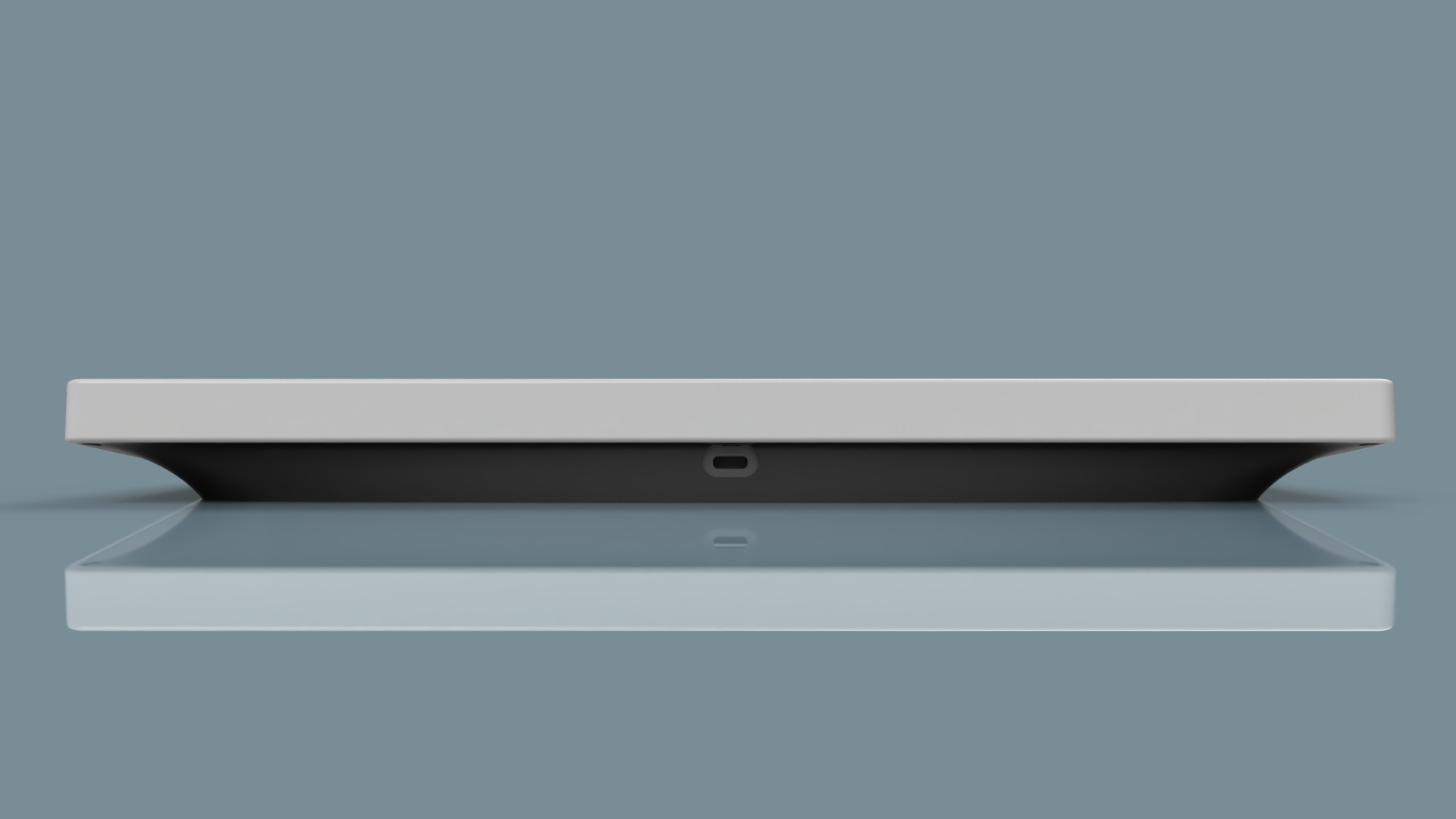
- The screw placement, most notably the one that sits below the USB connector.
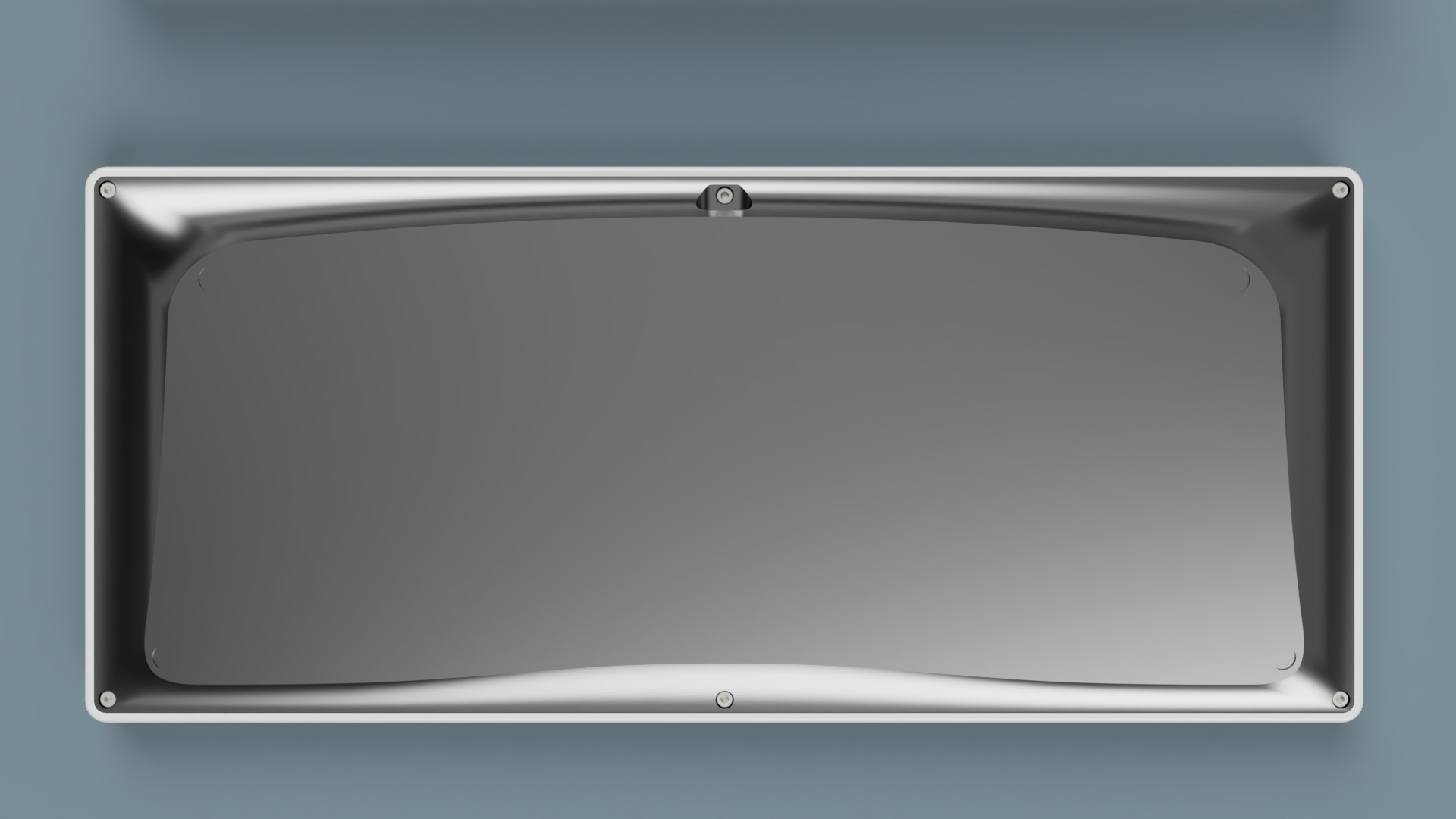
- The gorgeous curvy bottom piece, although you’ll see I did quite differently.
- An inspiration for the renders, you’ll see a lot of similarities in mine (obviously the execution is amateurish in my case).
Here we are for the rendering galore.
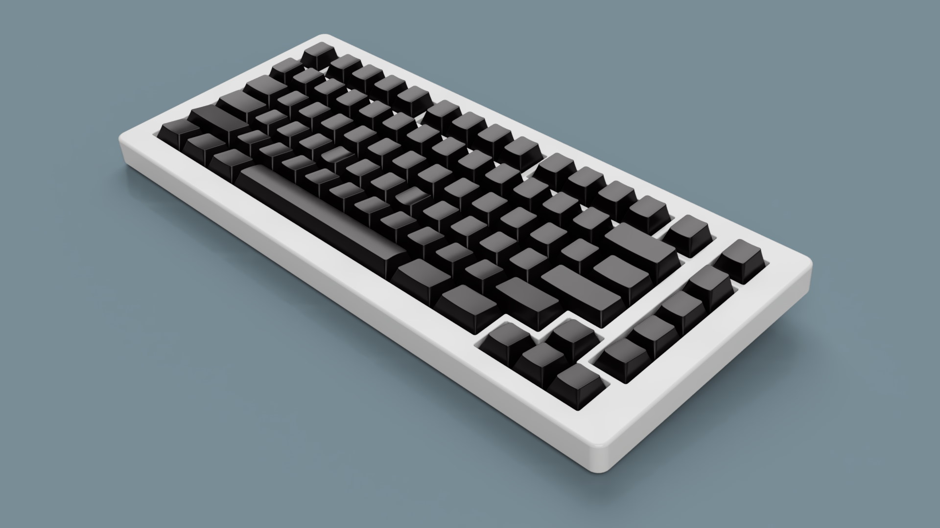
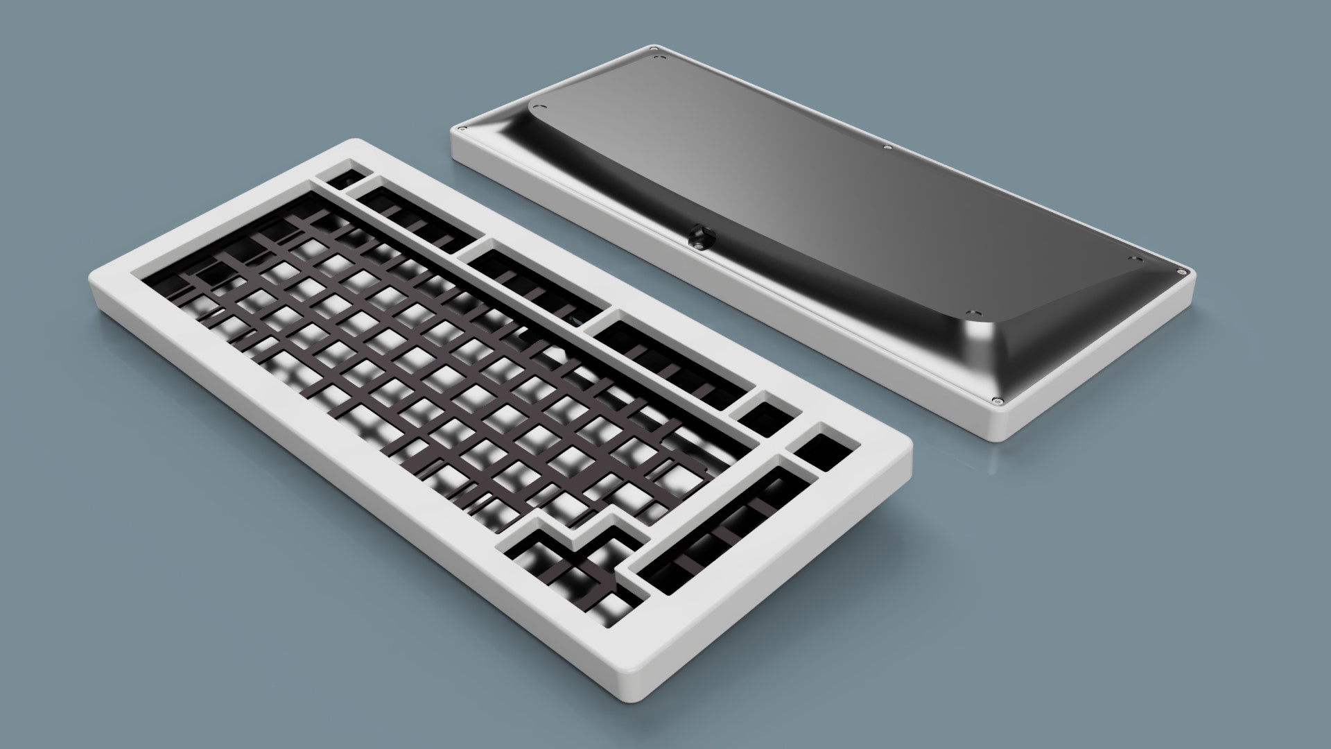
![Manta75_Top|690x388] (upload://7LllcG3Lp3KlLK8oeHrj74hWHef.jpeg)
Also did a few modifications for the plate design, more details for a future post
See ya guys!
9 Likes
Hi Rico,
thank you for sharing your dev process in such meticulous detail. Your process and results are a great inspiration. I hope you make good progress, can’t wait to see what’s next.
1 Like
Thank you @Andreas!
Very soon I’ll give news of the plate design
Love the slopes on the back!
2 Likes
I said that I made a few modifications for the plate design, but things went a bit crazy in the end
I always wanted to know how to make a plate with PCB technology like we often see but the plate flex is tuned for aluminium, not for FR4 (3 to 4 times softer than aluminium).
Also a custom laser cut aluminium plate is kind of expensive and you have bare alumioinum in the end, no color anodizing and sometimes no bead blasting leaving your plate with lots of ugly scratches.
But aluminium PCBs do exist, so was curious to test if making a plate with this material is actually possible.
The process so far have been:
- Basic plate design using AI03 plate builder and export to dxf.
- Further design under Fusion 360 for leaf springs, accoustic cutouts and other, another export to dxf.
- Final work on Kicad 5.99, send gerber to PCB company.
JLCPBC does not do aluminium so went to PcbWay instead:
- Matte black solder mask.
- OSP treatment for copper exposed areas.
- 1.5mm thickness.
And here is the result:
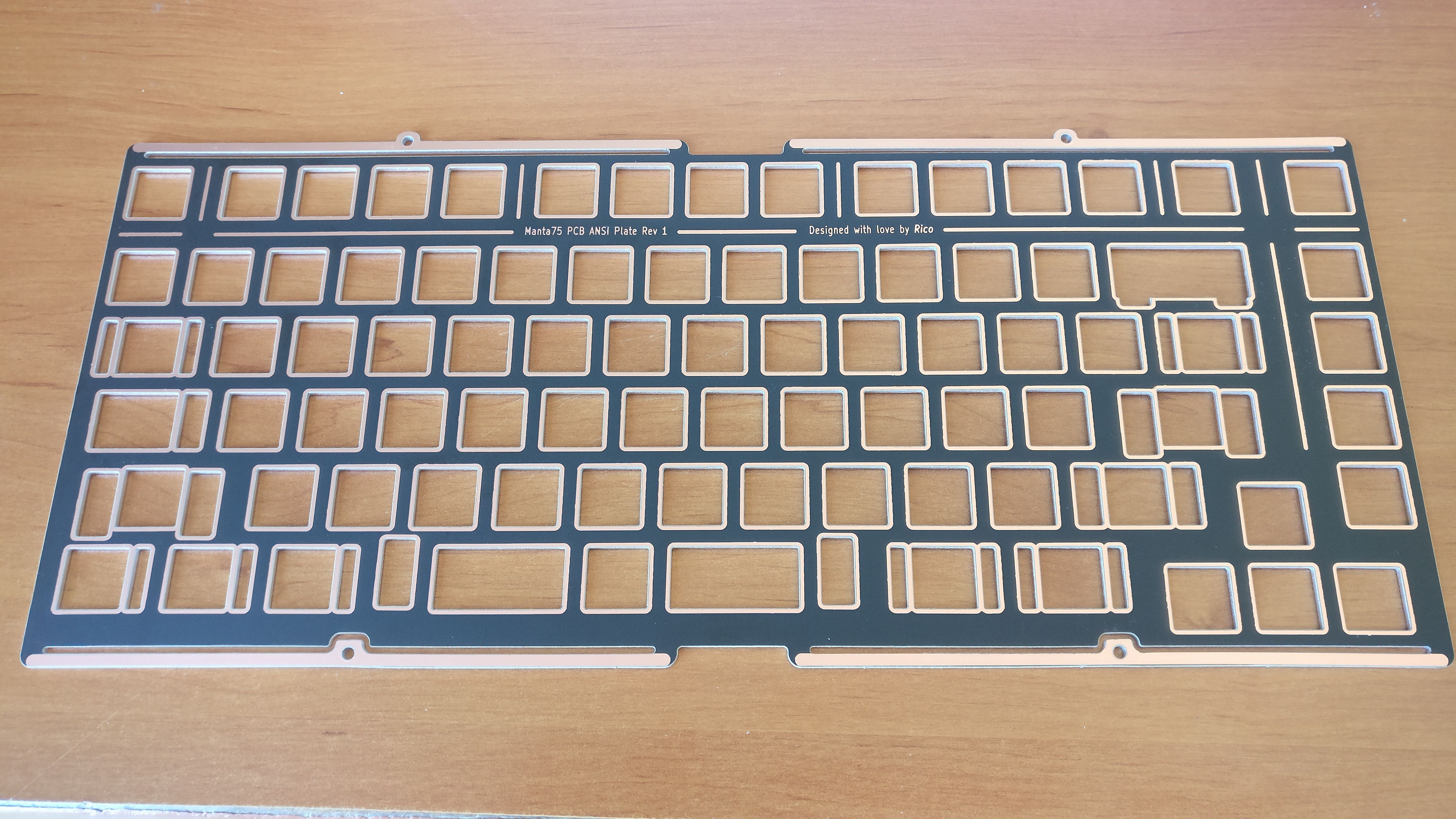
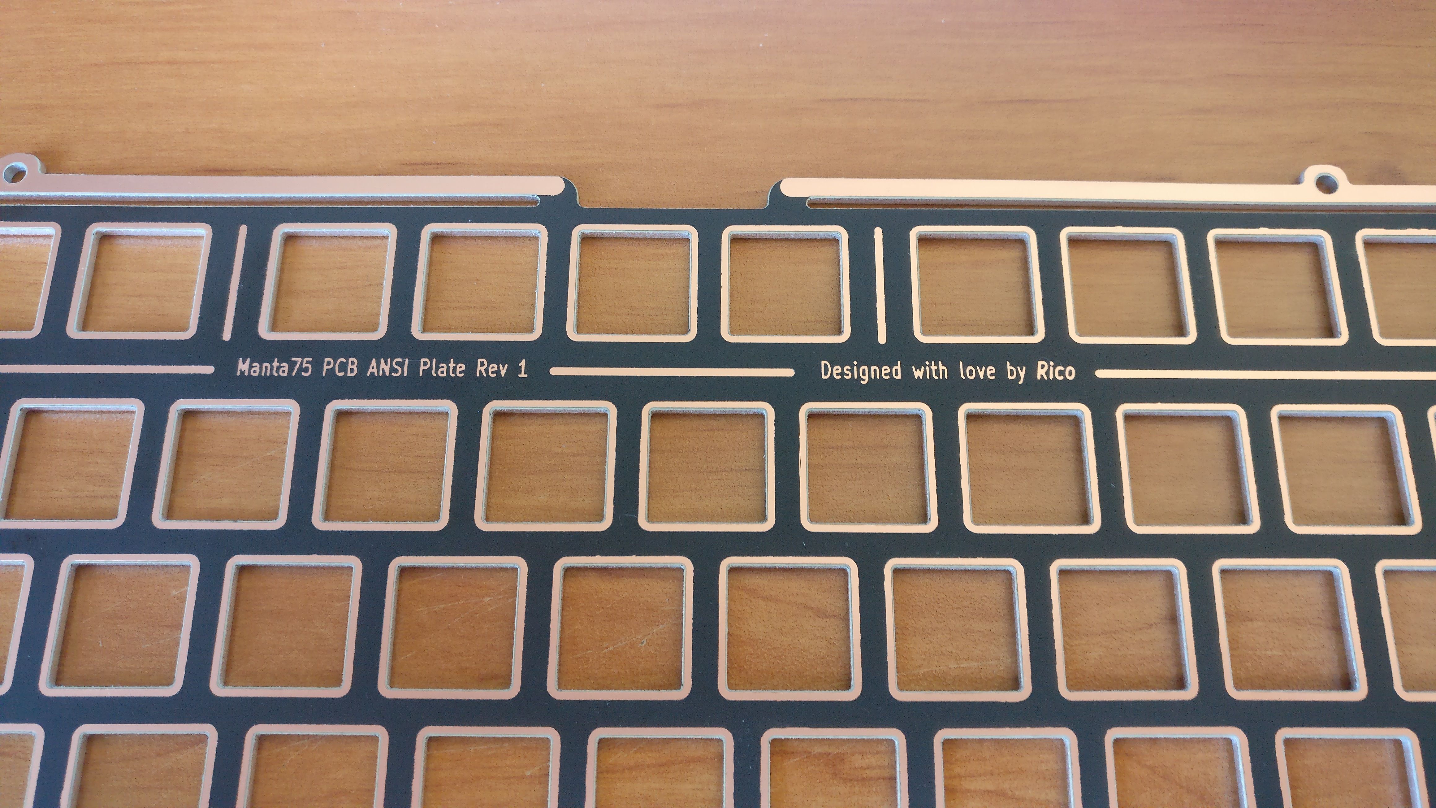
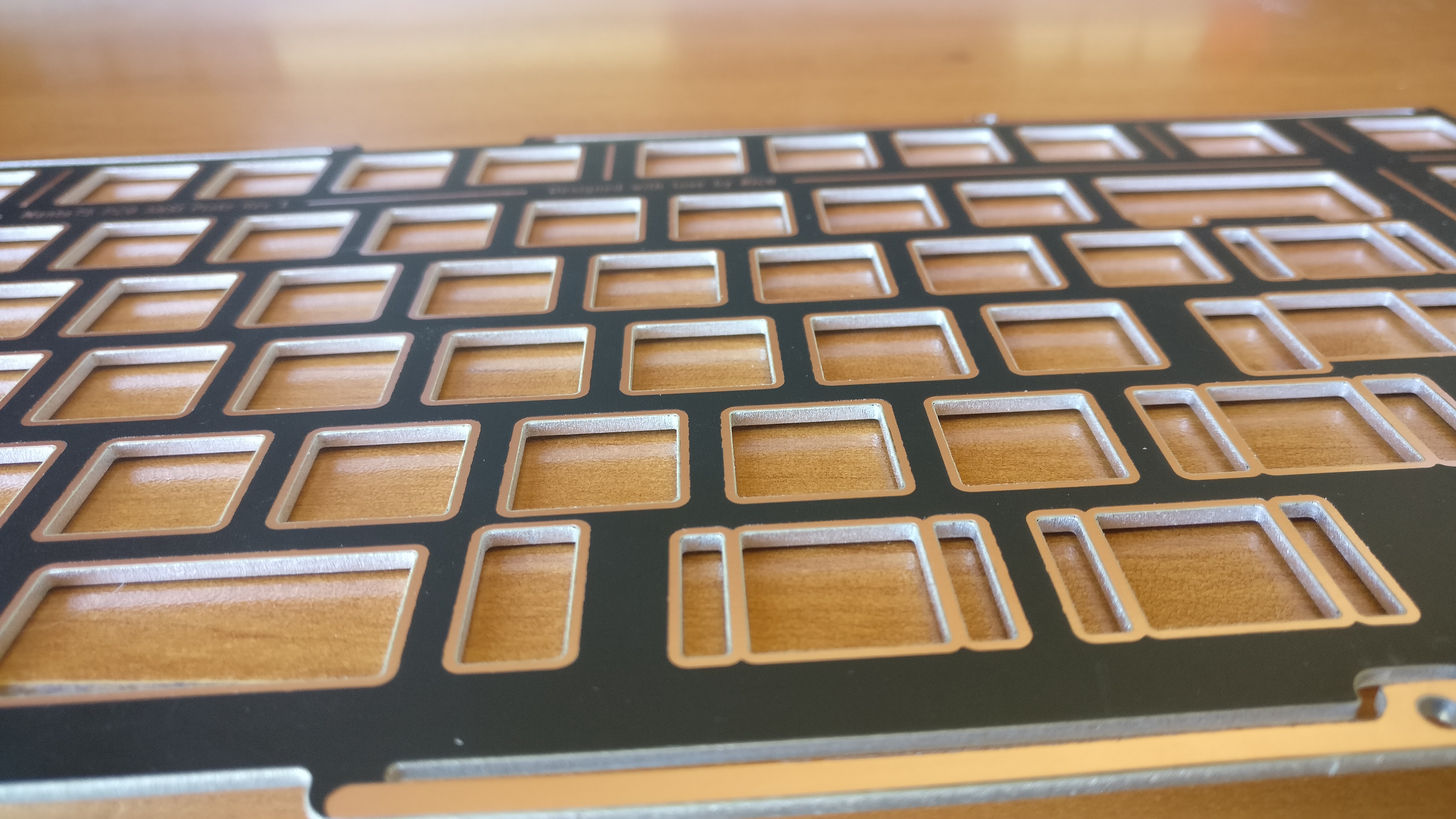
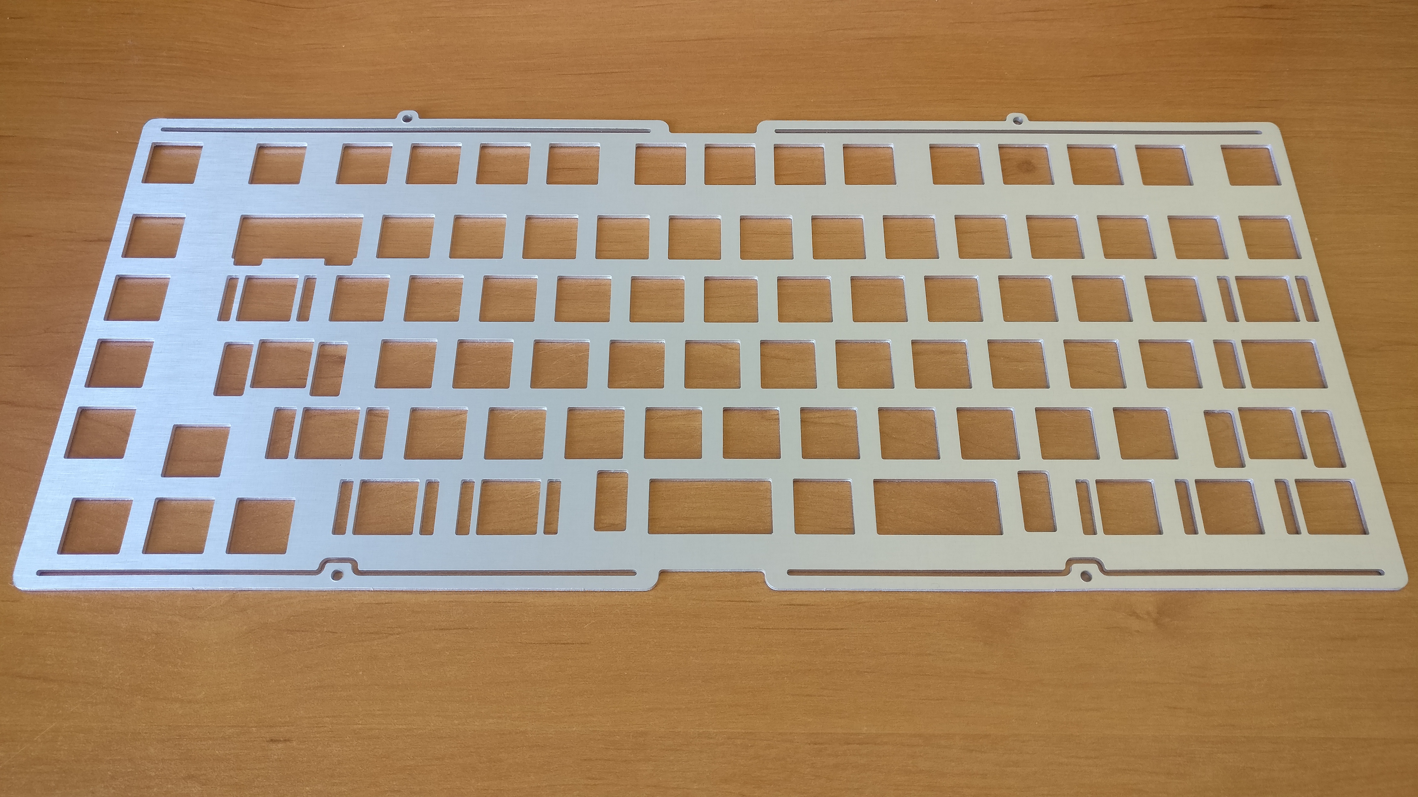
The good:
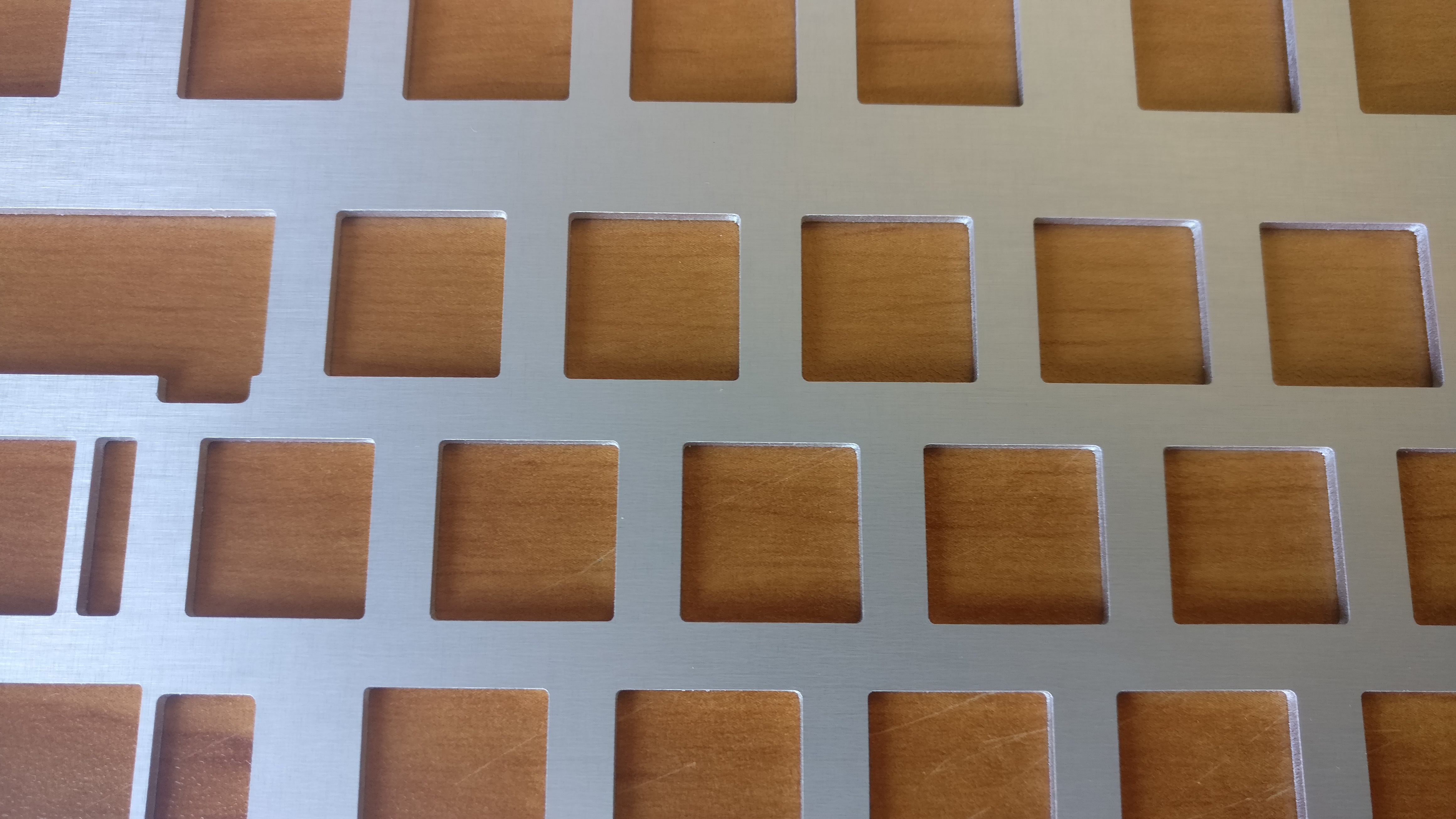
- Clean cuts with very good tolerances (it is CNC machined).
- Looks good.
- Same flex as aluminium plate.
- Less pingy than alumiinum plate due to slim FR4 substate at the top.
The bad:
- Lack of sharpness of OSP copper part; this may be due to the matte black solder mask, not very common for aluminium PCBs.
- Expensive for a one off; had 5 for around 190 euros shipped, but the more you make the cheaper it is.
See ya!
6 Likes
That’s really beautiful. Nice work.
1 Like
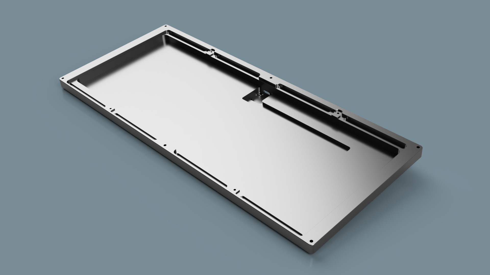
Hi everyone!
Just some quick words to tell you that the case design have been finalized and I decided on the CNC manufacturer to do the job.
Xometry EU will once again take in charge the CNC machining and finish of the cases.
This time four boards will be made and all in the same white colorway for the top part as pictured in the renders.
No anodizing this time:
- all top parts will be powder coated matte white (RAL 9010).
- bottom parts will keep their raw metal color, only buffing with Carnauba wax will be done to prevent tarnishing/oxydation.
The first three units will be all 6061 aluminium.
The fourth unit (my personal keyboard) will be a bit special with another material than aluminium for the bottom part
Order is sent, payment is done (outch) now have to wait at least one month before seeing the result
See ya!
4 Likes
I am guessing Vibranium! This build looks amazing I can’t wait to see how the cases turn out.
1 Like
Woohoo, I’m super excited to see how they turn out.
All the best for the parts to arrive as you expect them to.
1 Like
ROTF
Wouldn’t this meterial sound bad because it vibrates too much ?
1 Like
I am excited also , and I cross the fingers so that not too much things goes wrong