Wowee this has been an exciting journey! can’t wait to see how the builds turn out 
2 Likes
As I have roughtly one month before receiving the cases, I must progress on other topics in order to be ready.
First are the USB daughterboards as I only have 2 assembled.
So today I assembled 8 more universal C3 daughterboards 
Second is a problem I recently found on the main PCBs.
I showed the assembled PCB to my old friend and his son asked if it was working; I said “sure, look I connect it right now” … and the PCB was no longer working 
I had this weekend to understand what could be wrong with this PCB and if I could fix it, keyboard cases without working PCBs will not be of great use …
So I checked everything around the MCU with a multimeter and found two problems.
Problem 1:
Resistance between 5V VBUS and ground was only 500 Ohms!
It is very low, we usually find values in the hundreds of Kilo Ohms.
I already experienced a similar problem on the Winghead with low resistance between two MCU IO pins and knew more or less what to look in this case.
On the Winghead I had solder balls mixed with soldering flux that were acting like a 100-150 Ohms resistor.
So used magnifying glass, looking for something stuck between MCU pins.
And soon found the culprit: a tiny piece of dirt (metallic ?) that was in contact with 2 pins.
Once removed VBUS to ground resistance went back to 500 KOhms
I think this was the reason of a non working PCB as it probably happened during the storage.
Problem 2:
This one is interesting and frustrating at the same time.
USB D+ and D- inline resistors had a value of 220 Ohms instead 22 Ohms !
I checked on the BOM I sent to JLCPCB and in was indeed an error on my side, picked the wrong reference, so frustrating indeed
By chance I have lots of 603 22 Ohms resistors in stock, so I proceeded to remove the 220 Ohms ones and replace them by Ohms ones … on all the 5 PCBs I had.
Also took the time to check they were all in fact working nice and flashed the QMK VIA firmware.
Conclusion:
I once told that keyboard PCBs were quite forgiving, and this is kind of a proof.
The first assembled PCB was working perfectly with D+/D- inline resistors with a value ten times higher than preconised!
Interesting isn’t it ?
3 Likes
Hello all,
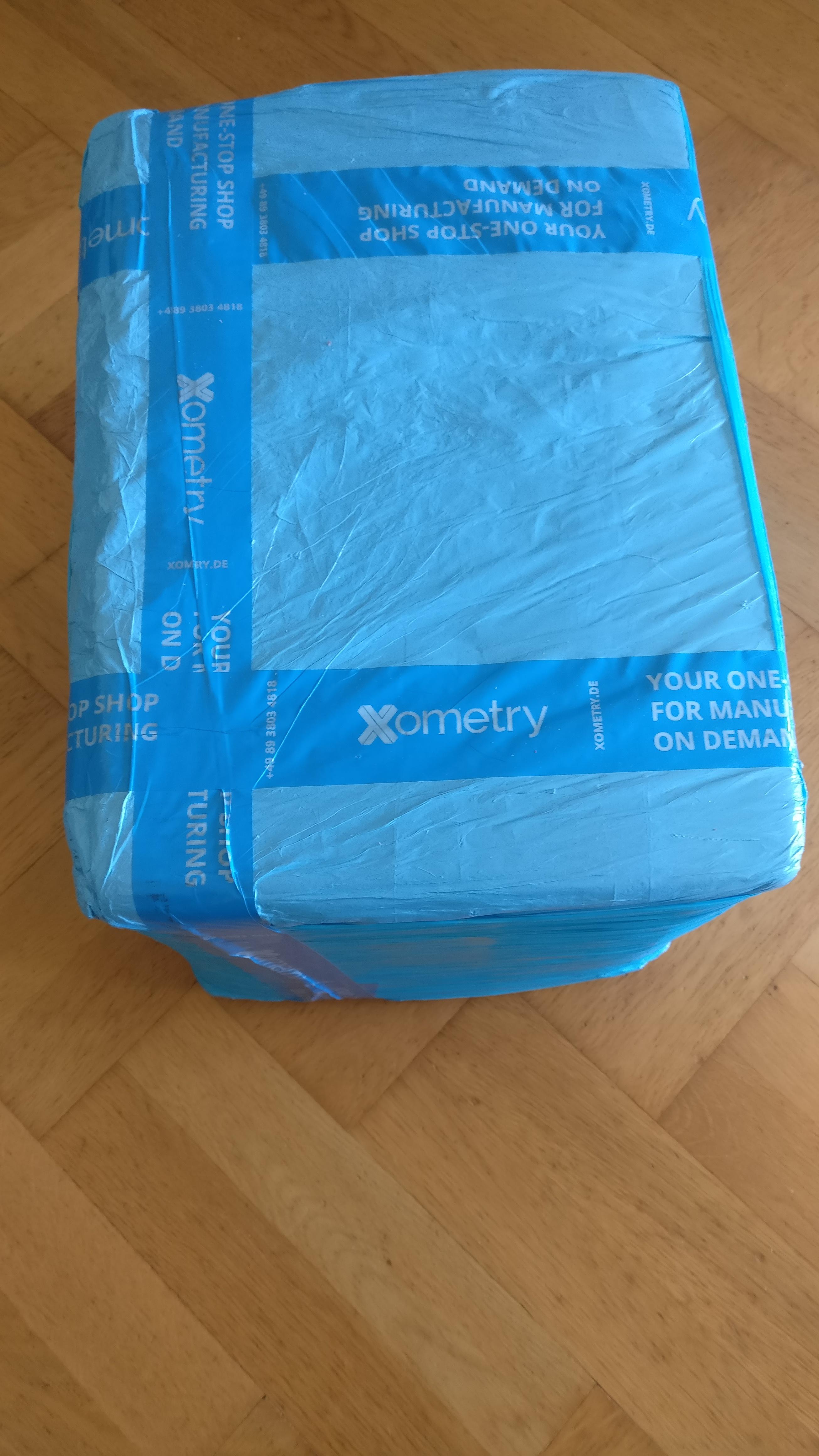
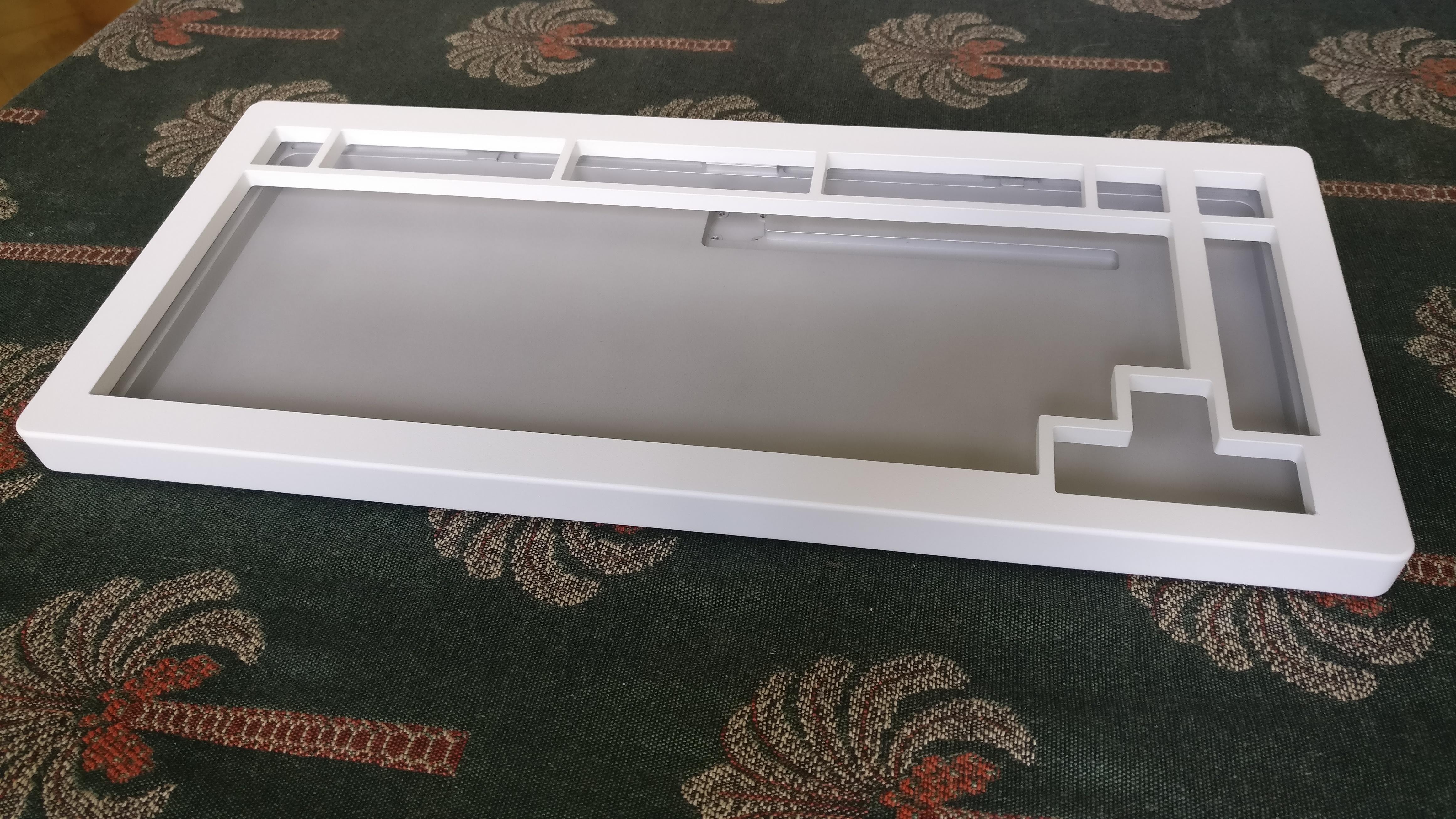
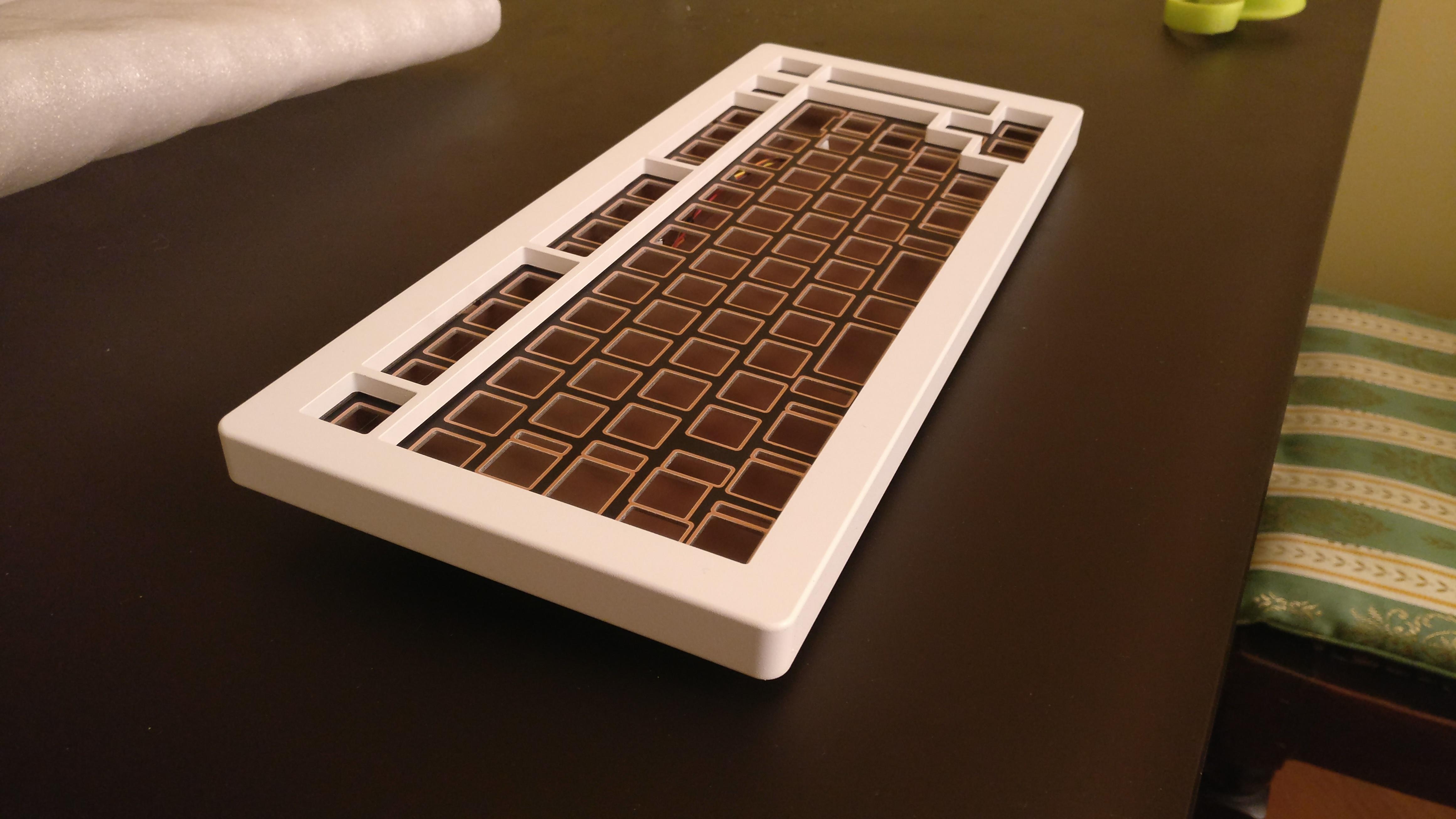
Today is a big day, I received a precious package from Xometry containing the cases.
I did carefully checked all pieces, looking for possible finish defects, verify the fitting, that all threads are correctly taped, …
And the conclusion ?
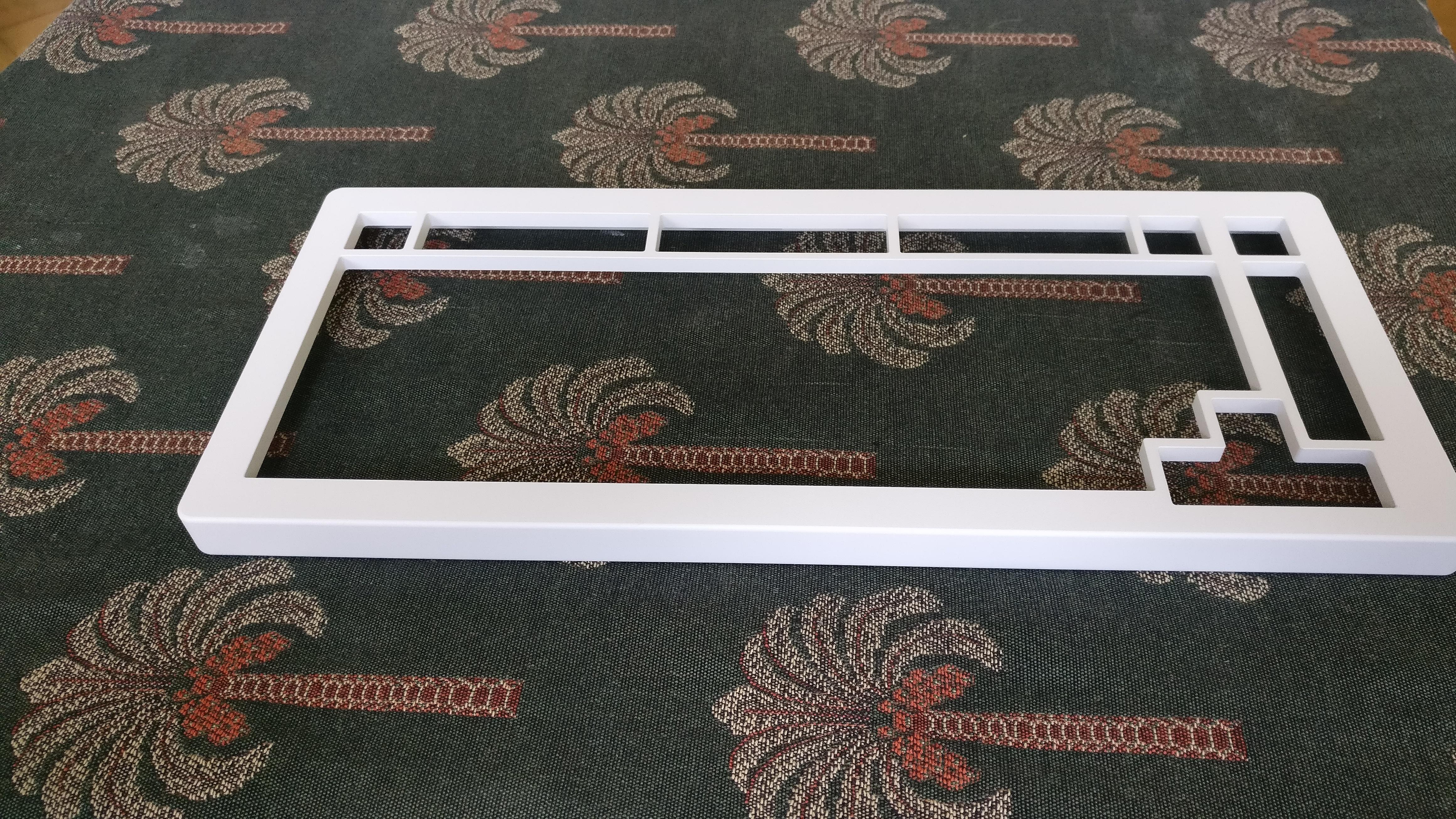
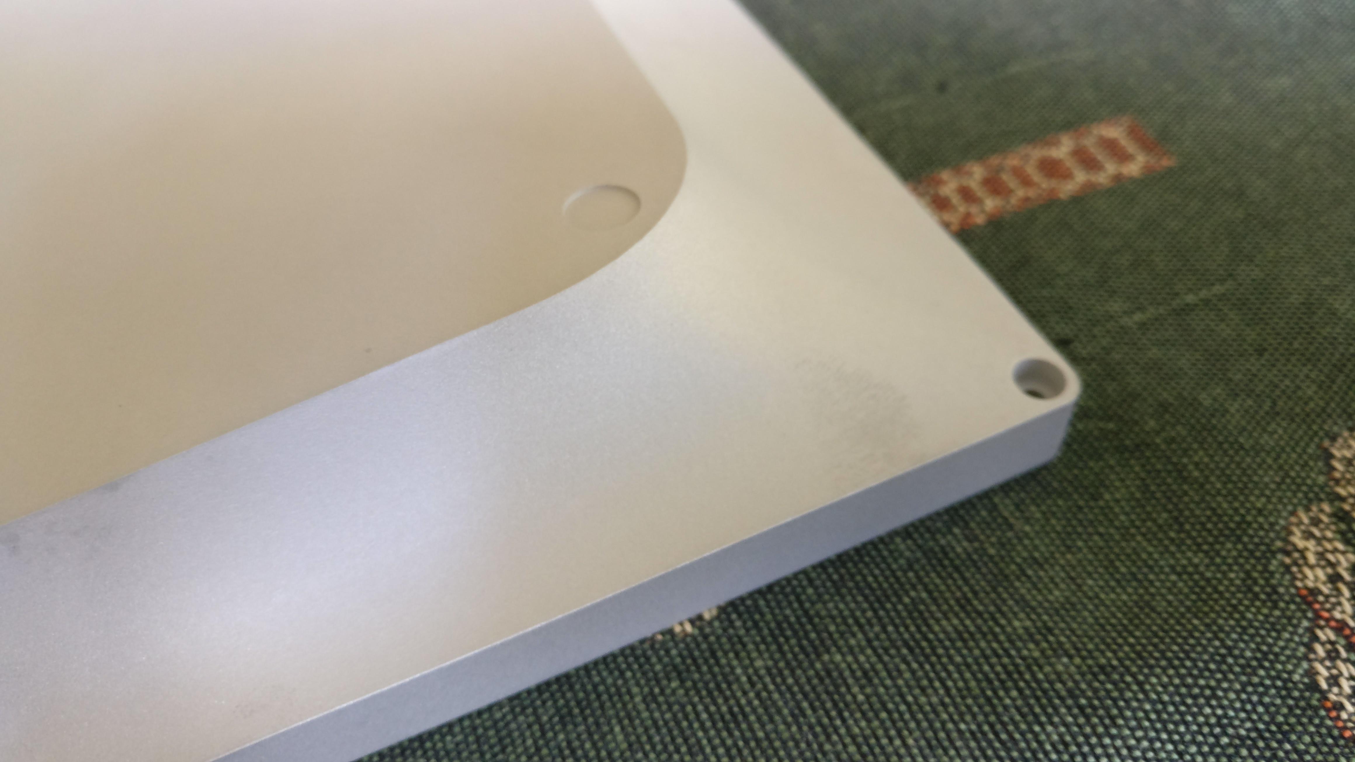
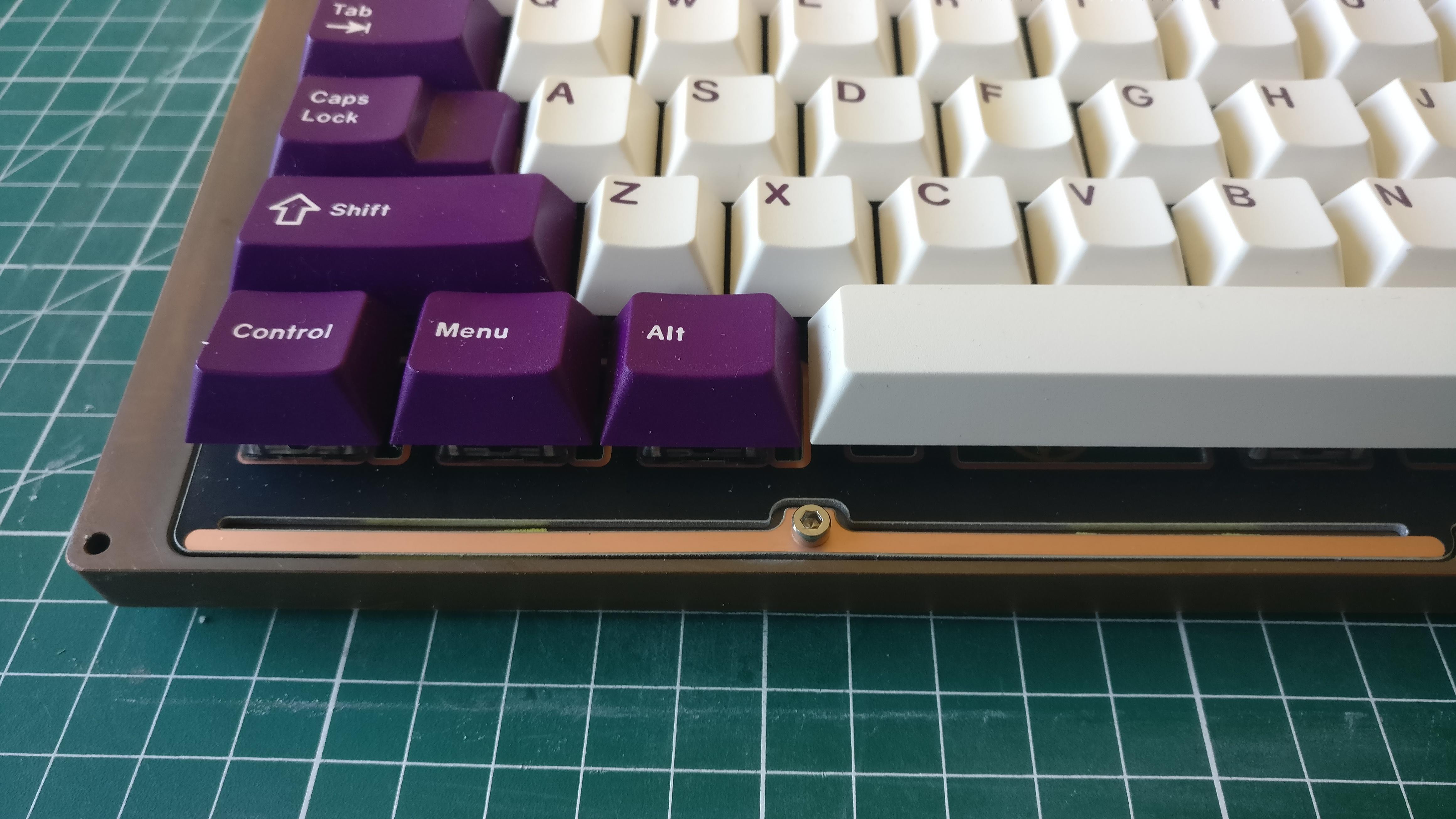
While they has been a few very minor finish problems that you can’t see when keyboard is assembled, and a stupid design mistake on my side (easily fixable by touching the plate), I have been very happy by the result.
The powder coat has been applied greatly, very thin 2-3 mils thickness, the white comes great and it is deliciously slippery to the touch.
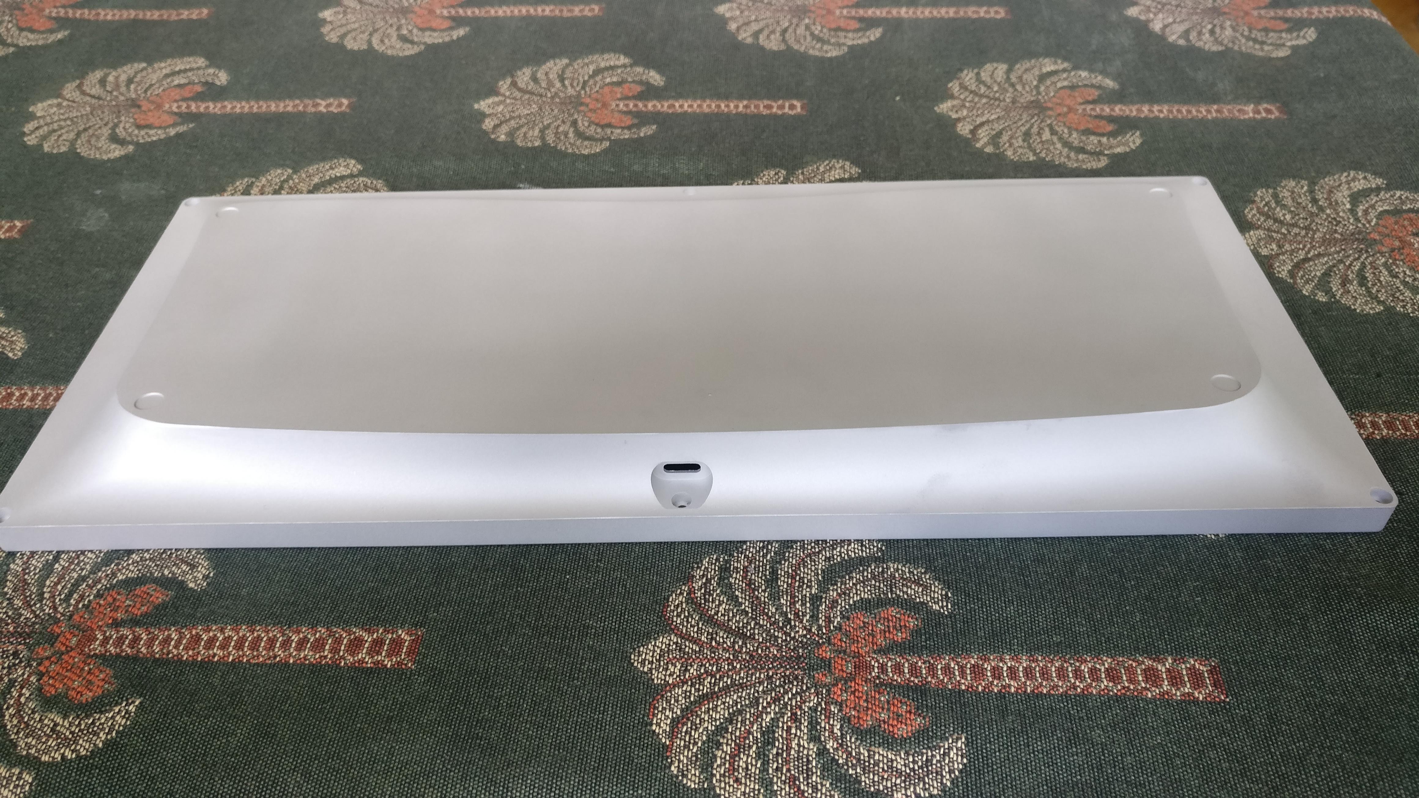
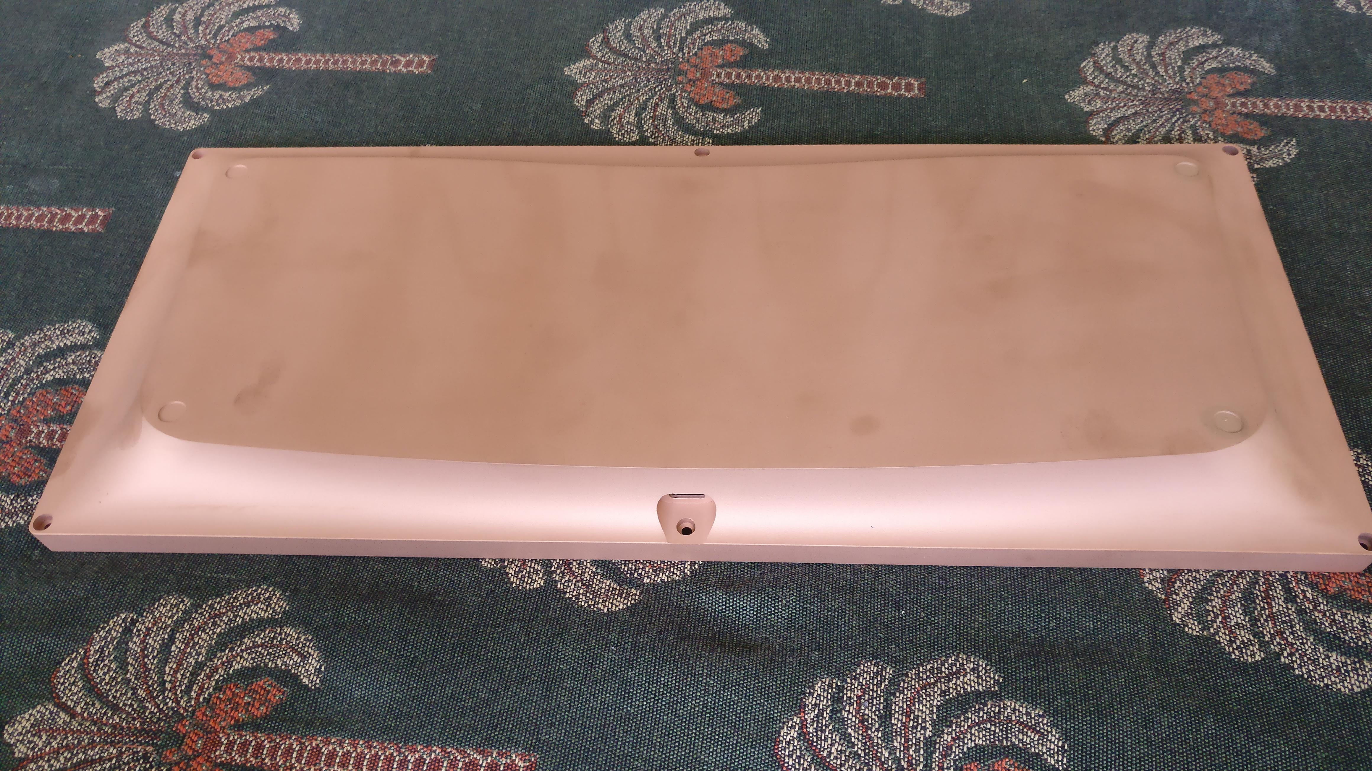
Bottom pieces are raw with just a little glass bead blast, they will not stay like that as they are very matte as a result.
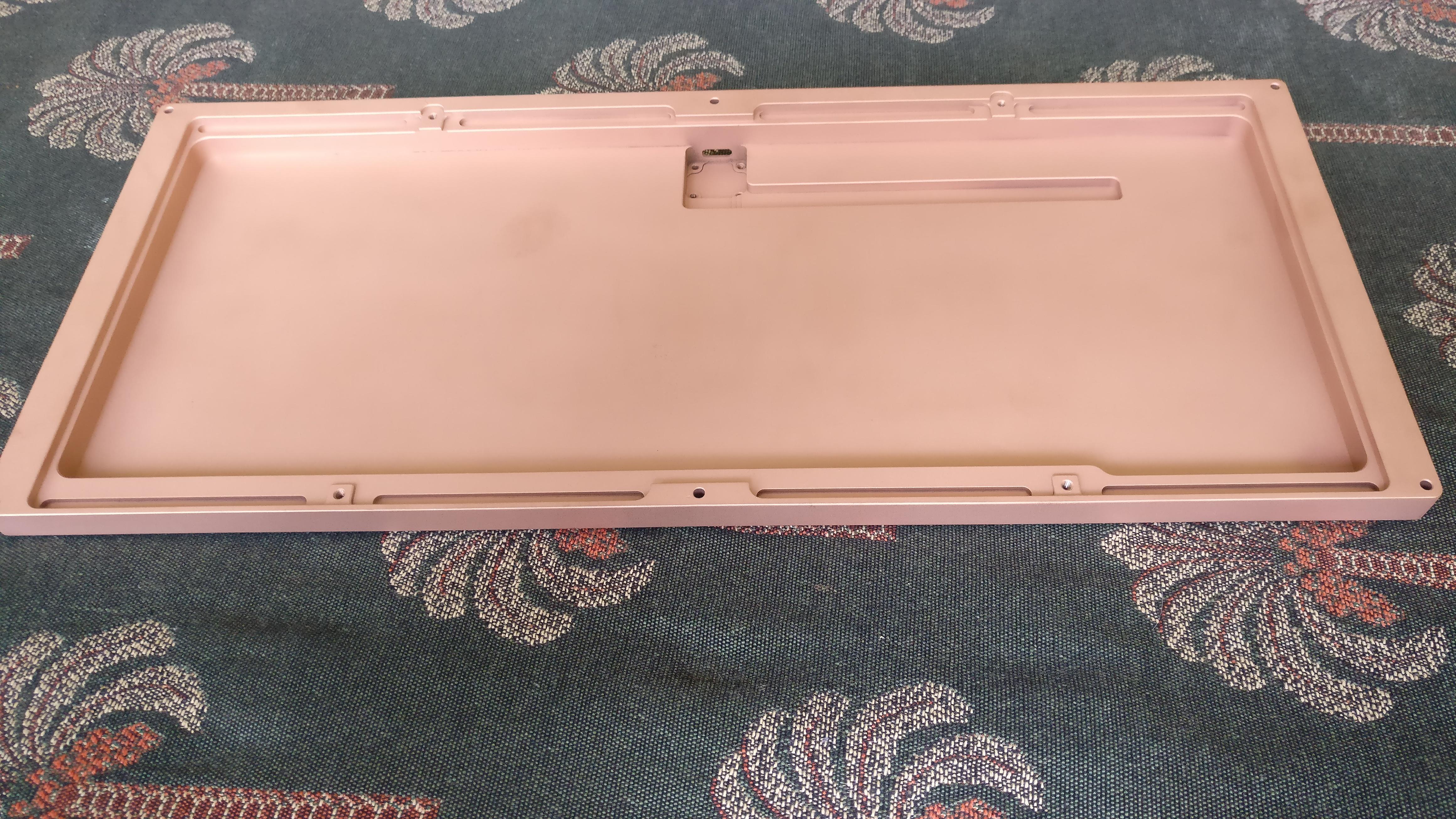
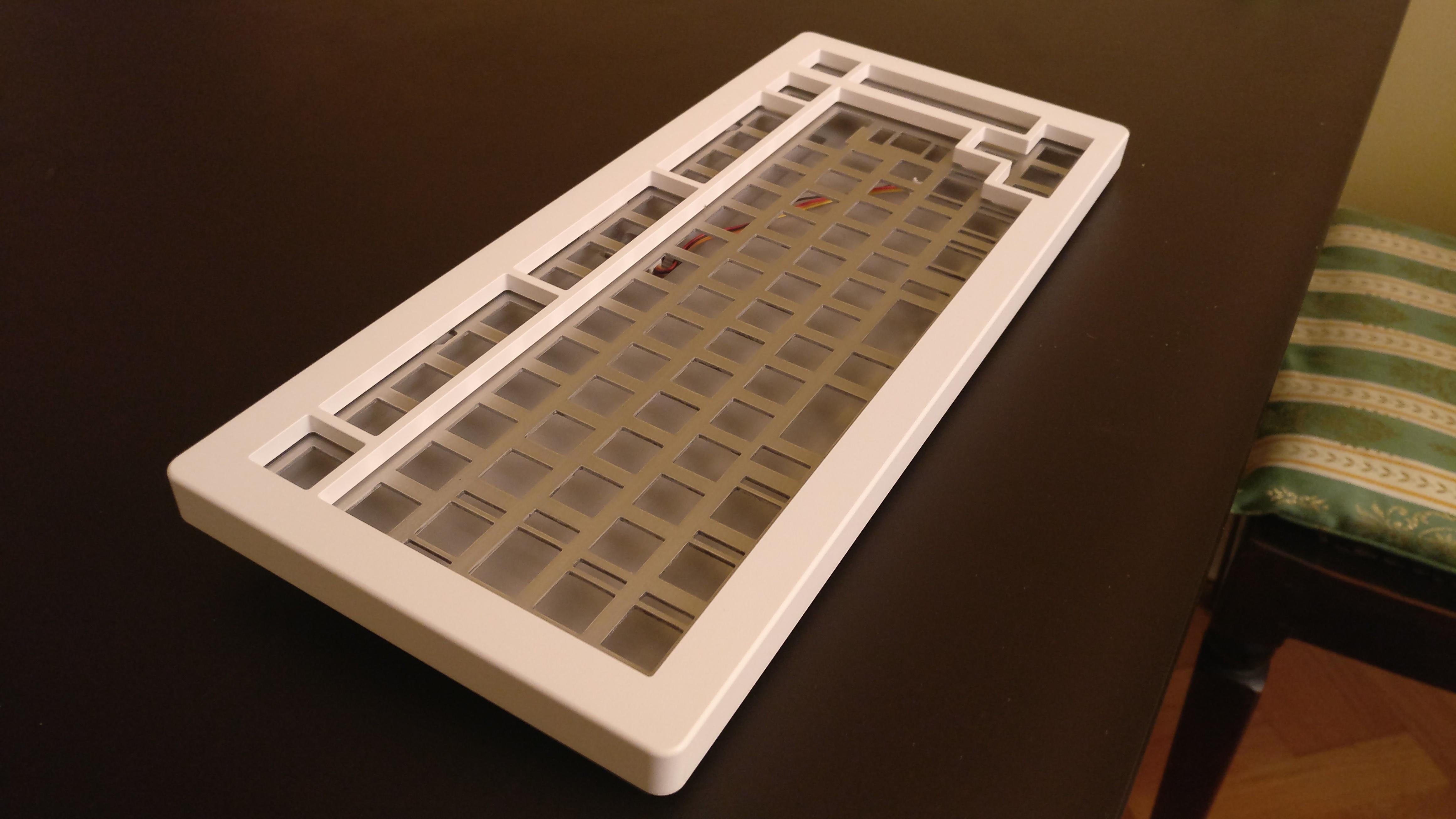
Here is the aluminium version, 3 pieces in total.
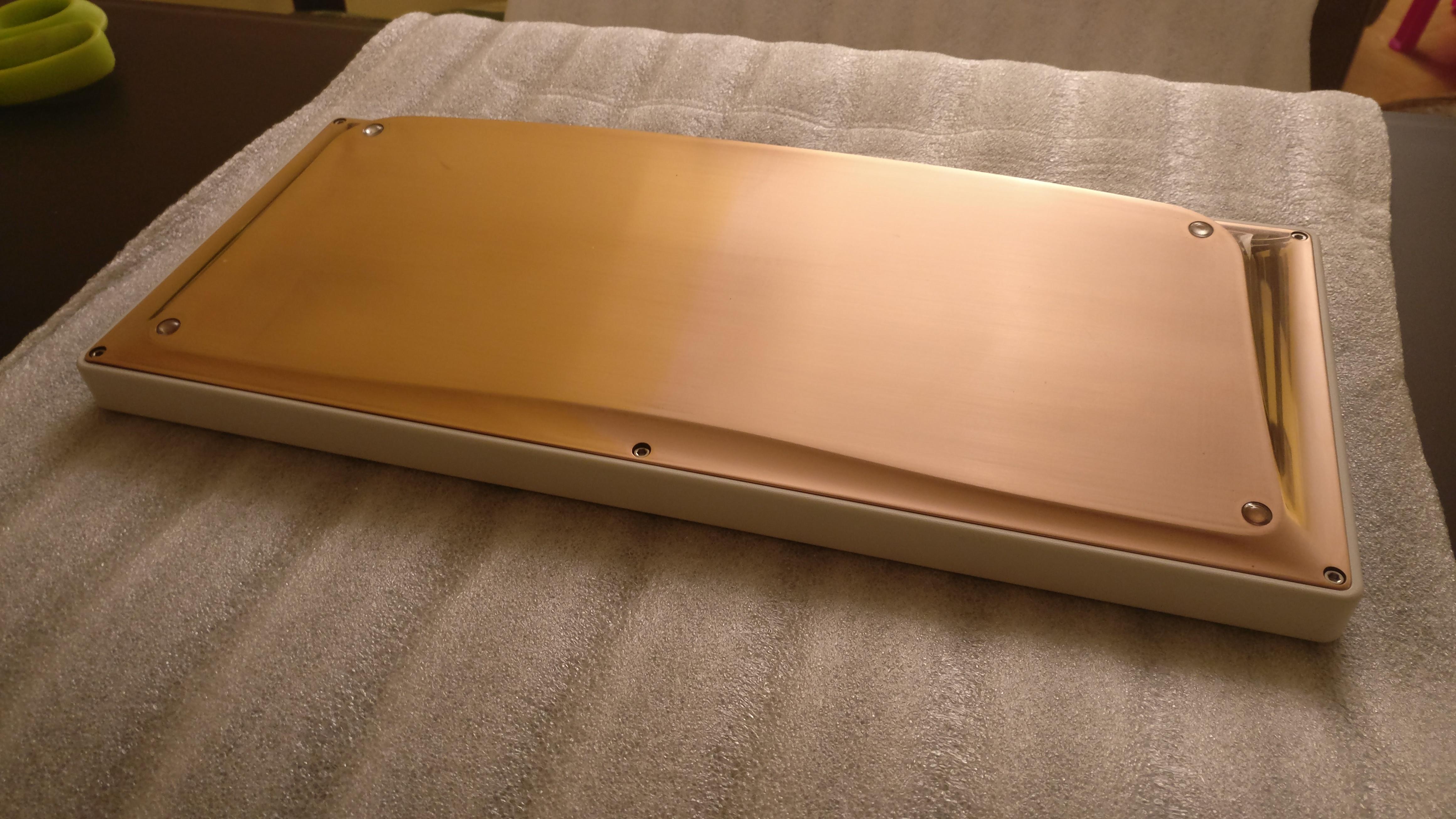
And for one of the pieces I went crazy and made it solid copper 
This beast alone weight more than 4Kg !
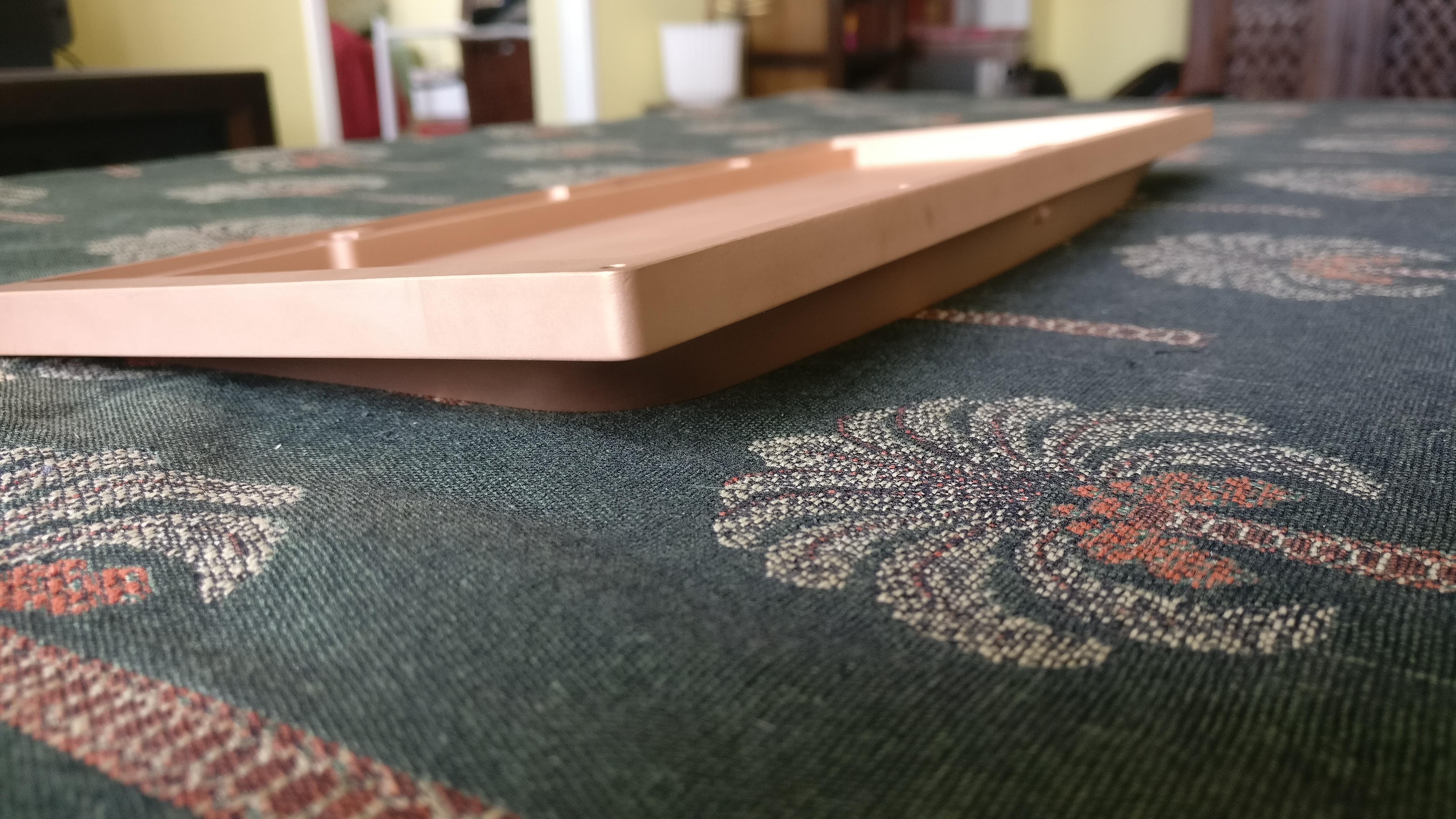
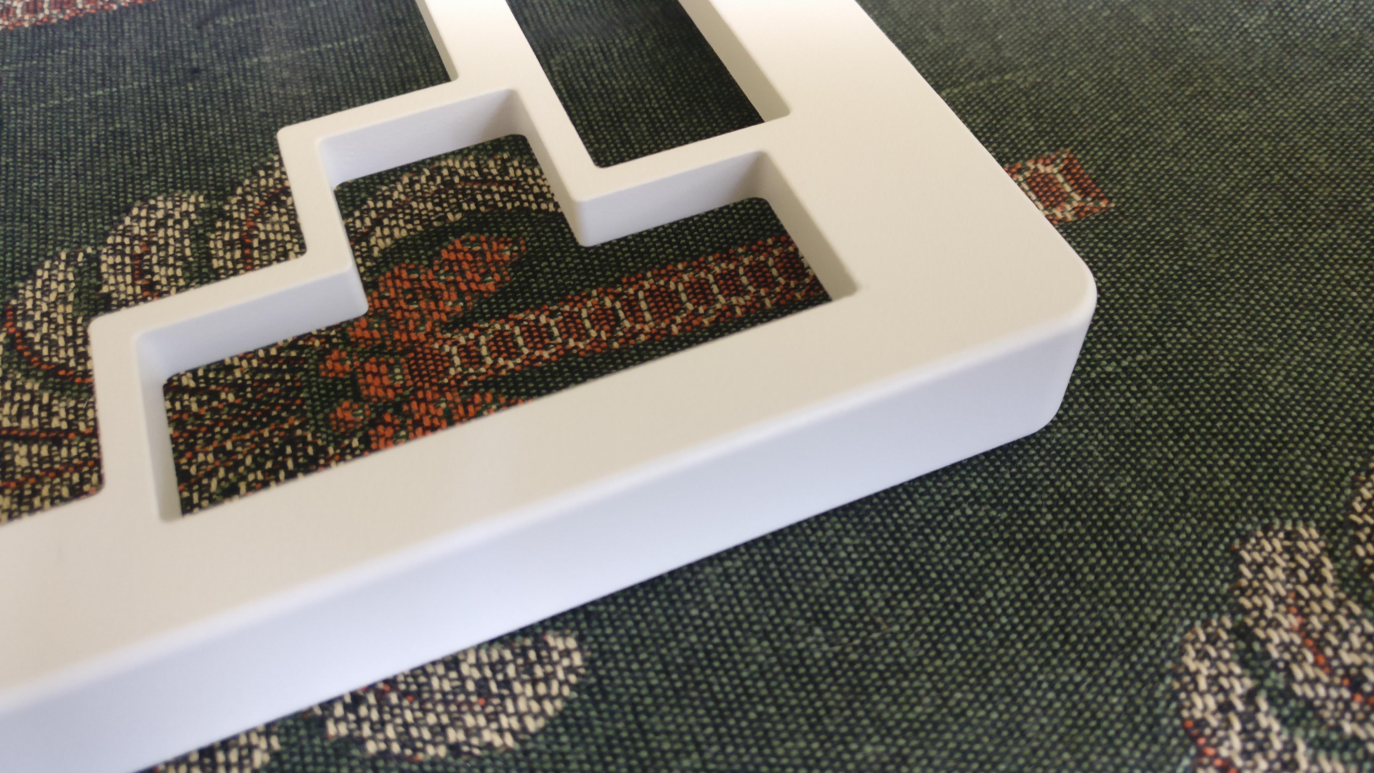
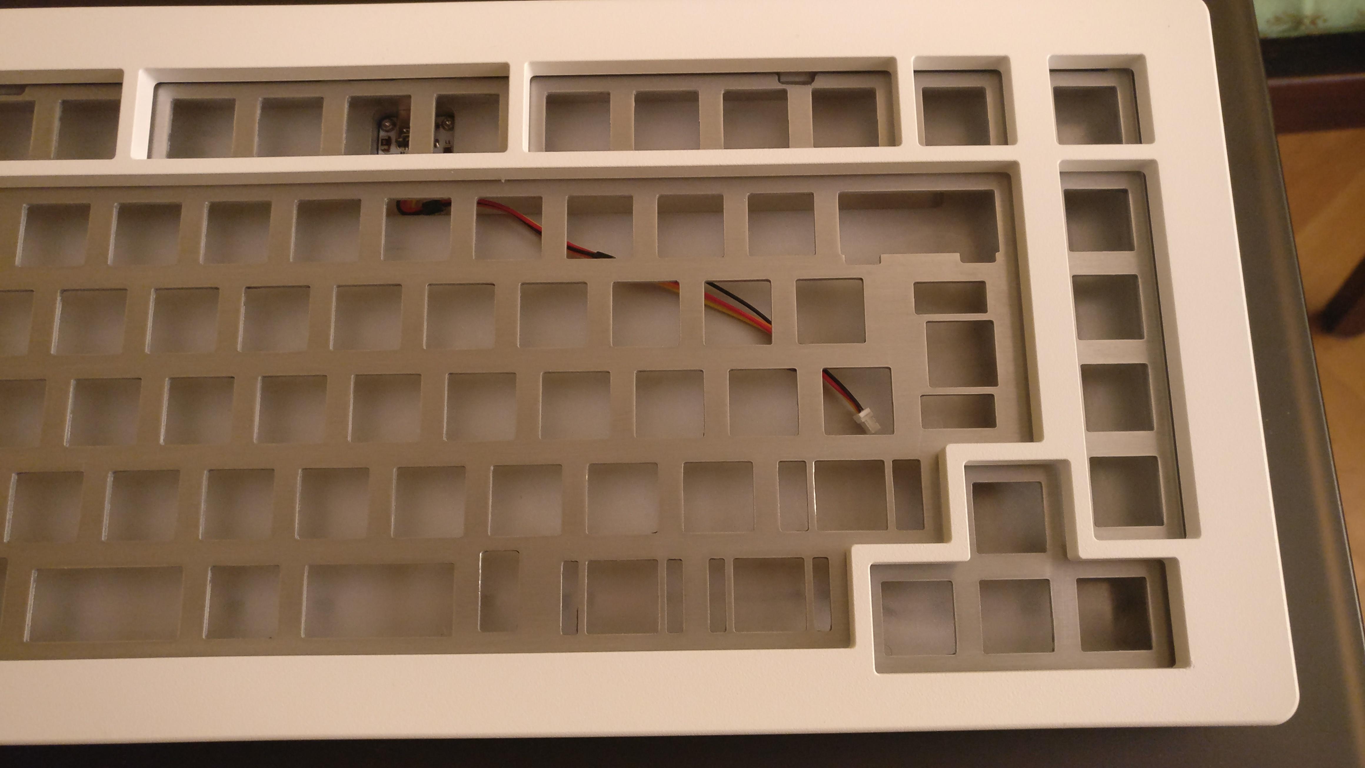
And a few images with various fits.
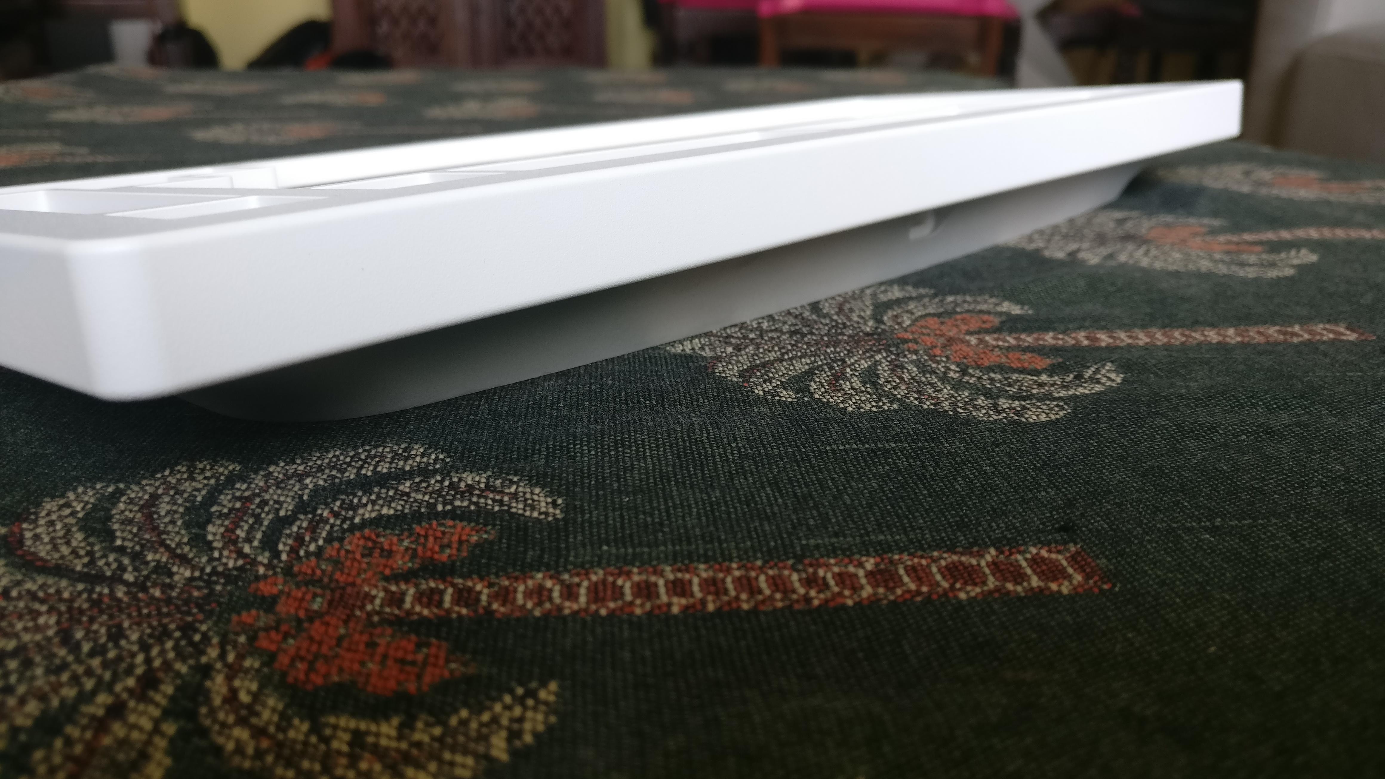
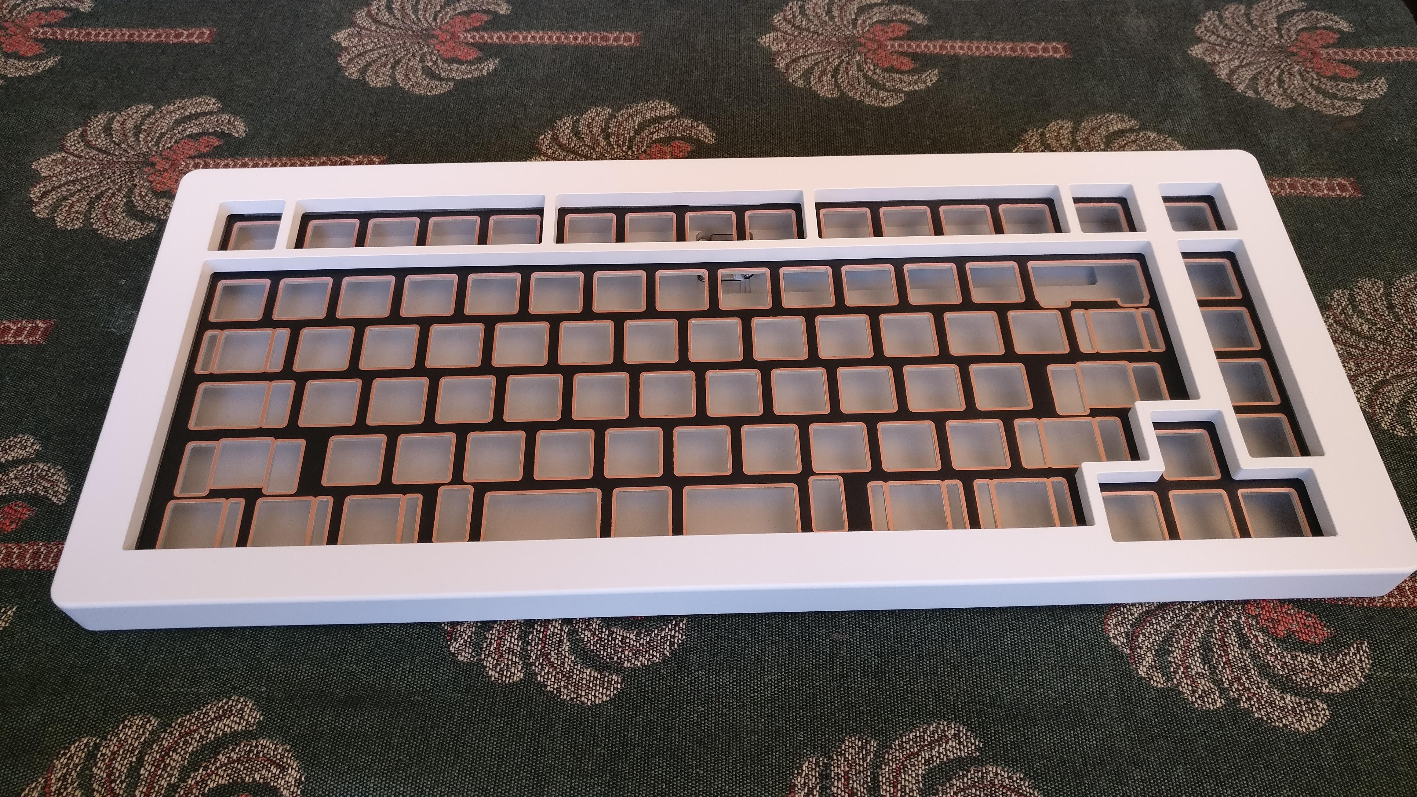
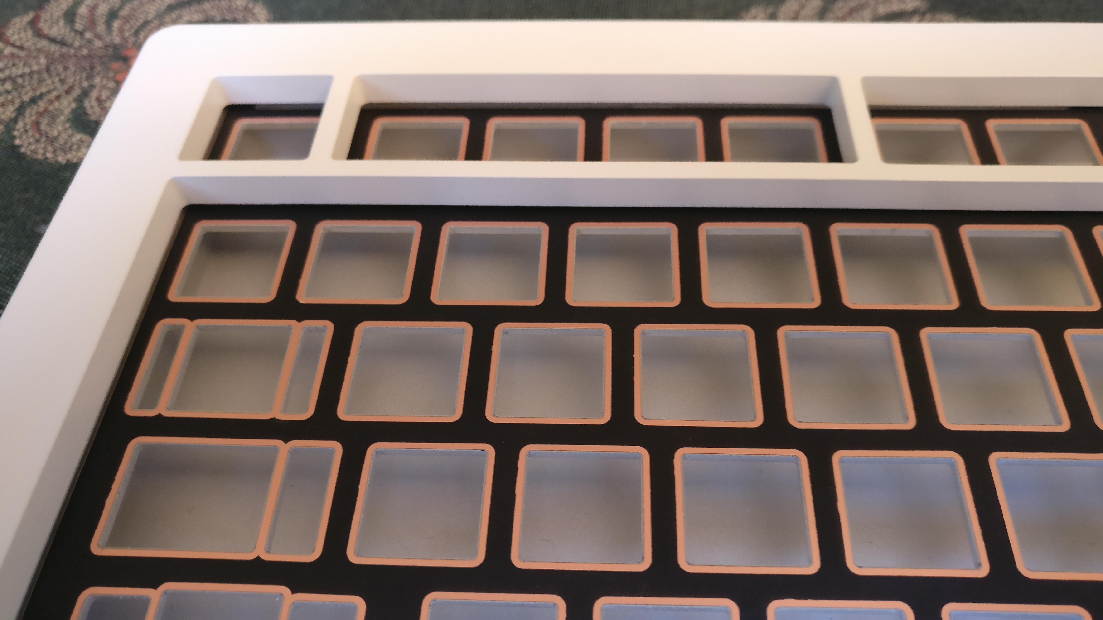
Fit tolerances are tight as hell
Super happy by the results
But still a lot of work to finish those up…
10 Likes
Oh wow. Absolutely eye catching. I’m glad for you it turned out so nicely.
1 Like
Love it. Really nice design
1 Like
That’s really cool to have something in person that you’ve designed. It’s looks great!
1 Like
I feel like a broken record when it comes to your posts, but this is really nice work. Thank you for sharing!
1 Like
Thank you for the kind words!
Haha, I understand what you mean about broken record
It has been nearly a year since the first post, that is a loong time…
I should revise when to start posting for the next project.
Although, to be honest, announcing it early forces me to go to the end of the process 
1 Like
I think it’s fine to post when you start out. It shows just how much time a project can take to complete and sets the appropriate expectations and appreciation.
These days with cut-down YT video’s it all looks too easy.
1 Like
Hey!
Just a little bit of update
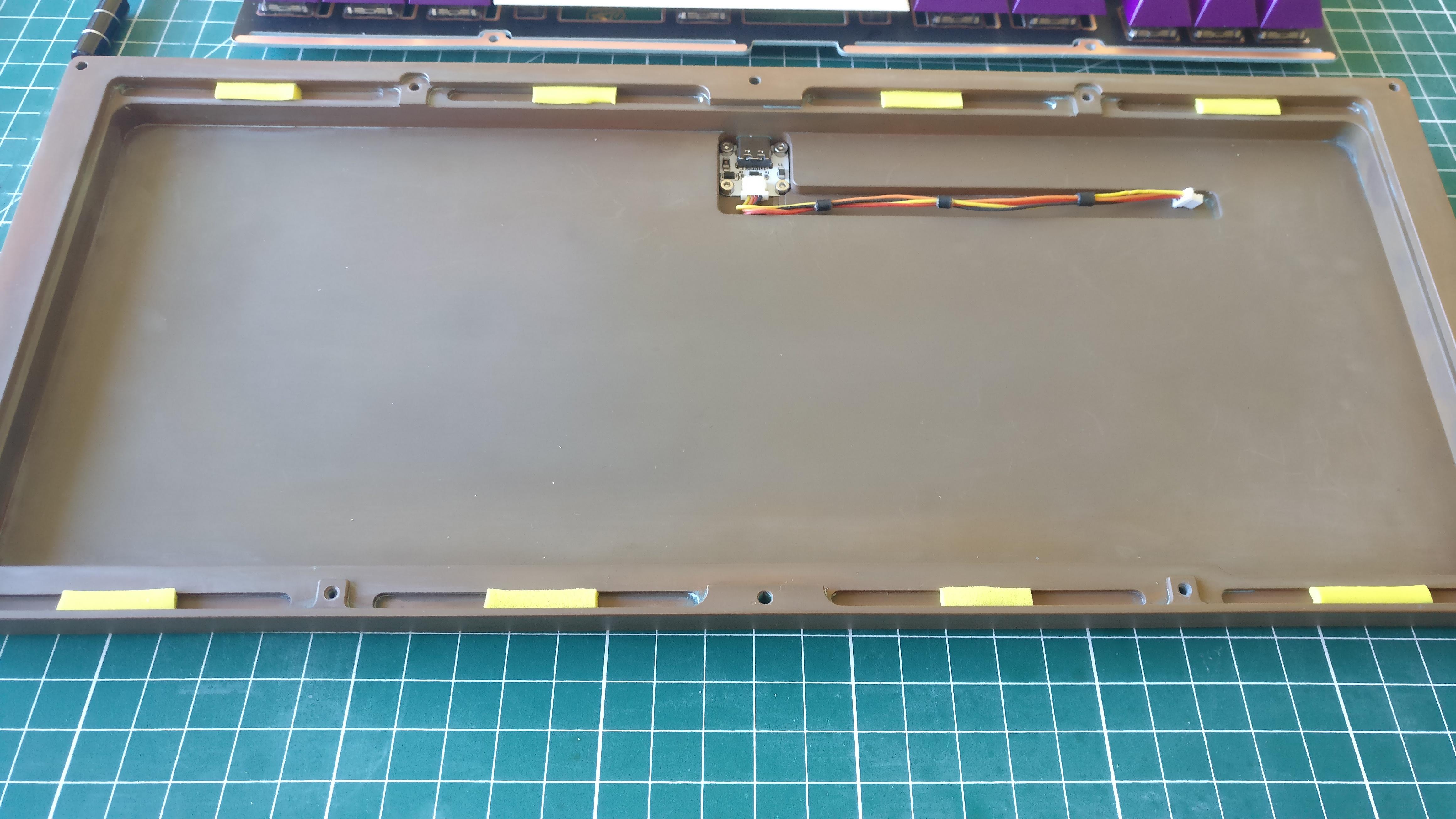
I took me time put I finished preparing all the cases for a future assembly.
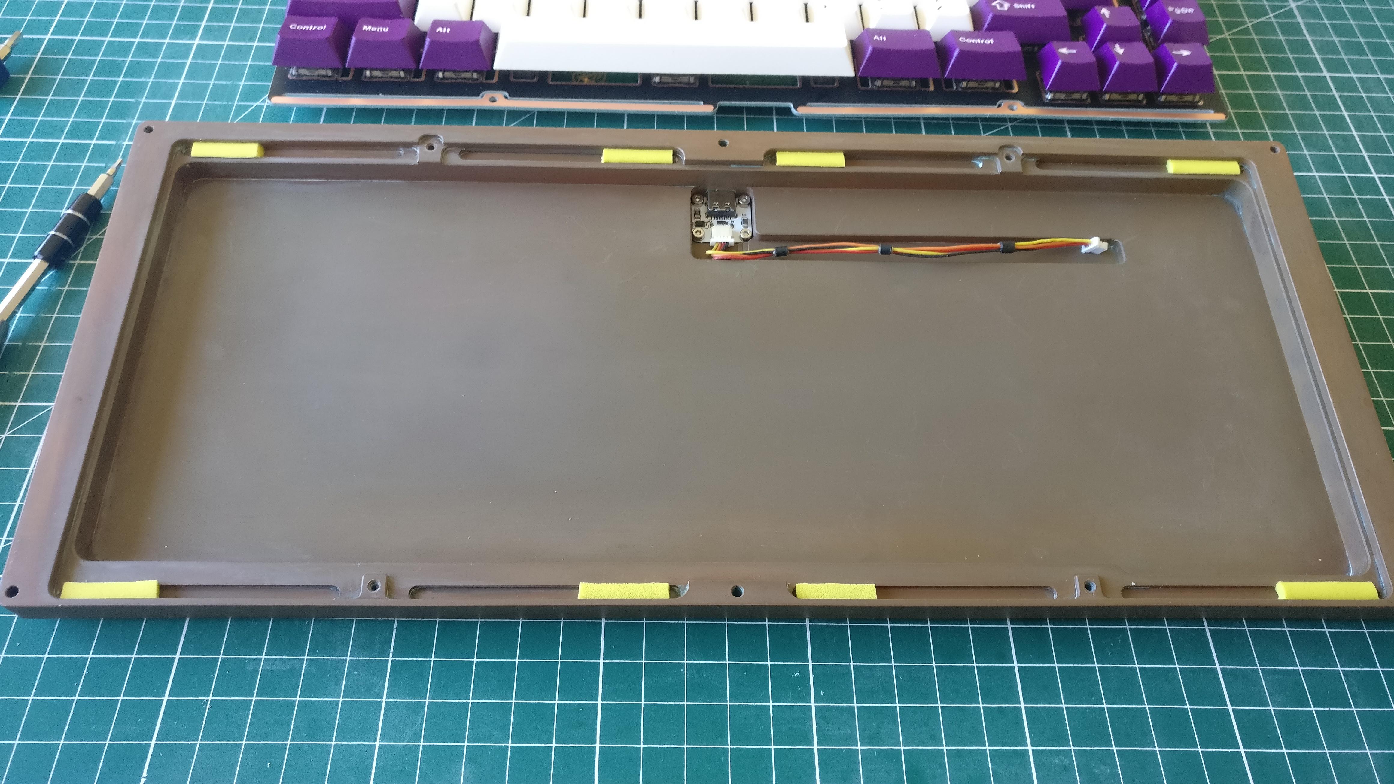
All PCBs working and Vial flashed, USB daughter boards ready and screwed on the bottom piece, custom JST cables made (I used very flexible 30 gauge silicon insulated wire).
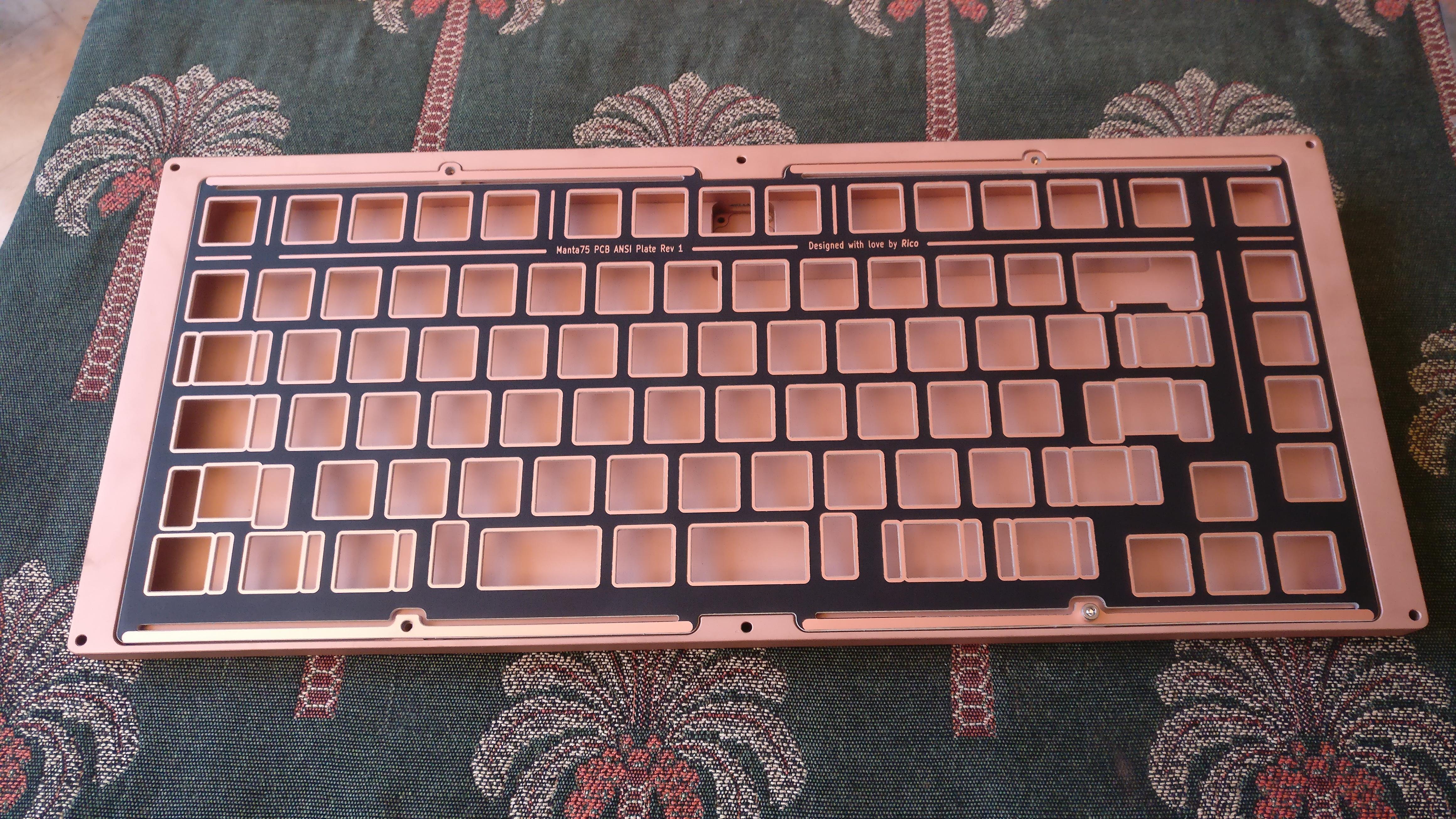
3 LaserBoost made aluminium plates have been hand brushed finished with 500 grit sandpaper, all ISO specific.
For 3 keyboards this will be Azerty layout guys
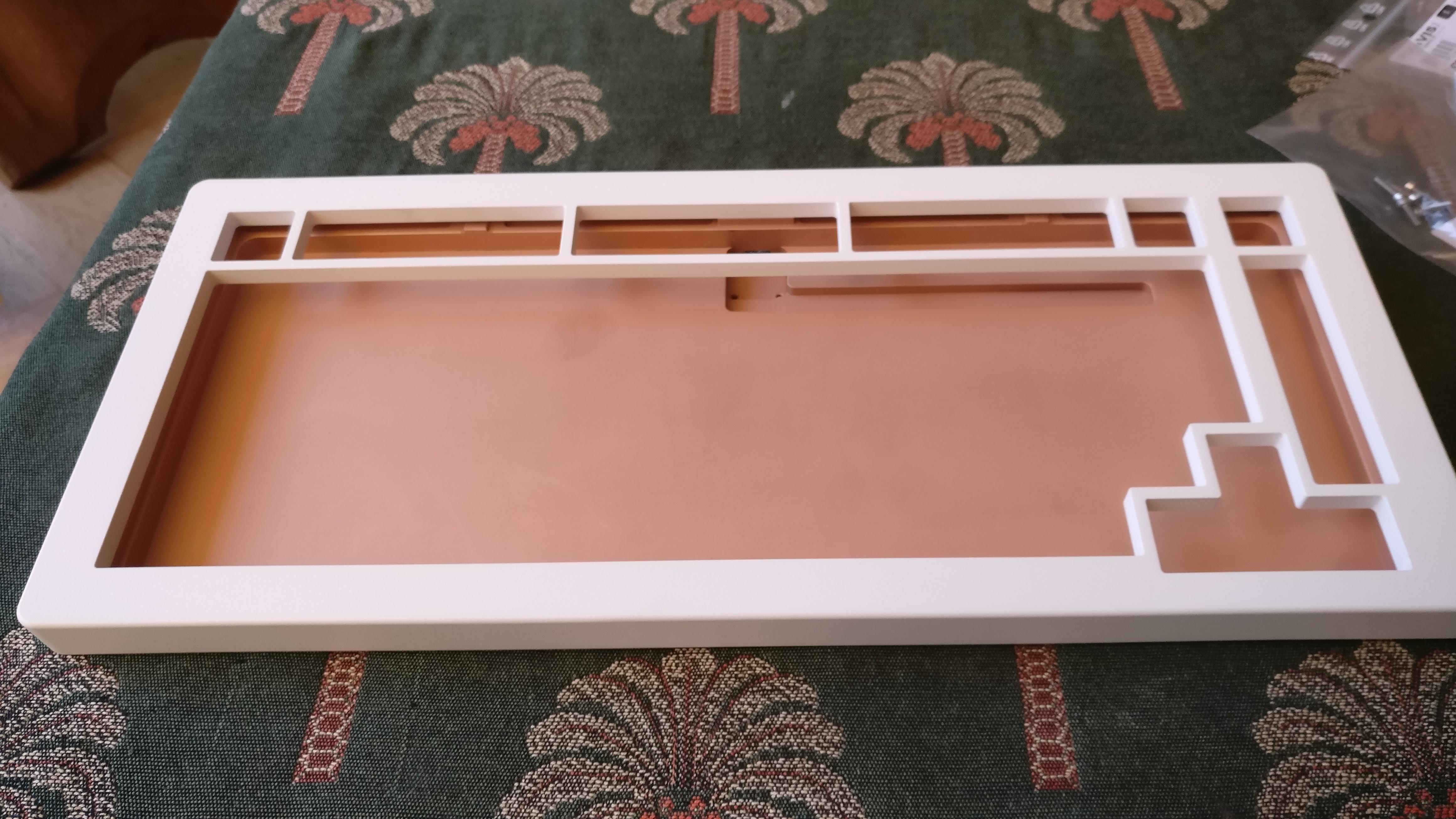
Also the bottom cases have been prepared to their intended final look.
The first two I kepted their bead blasted finish and just added Renaissance Wax for protection.
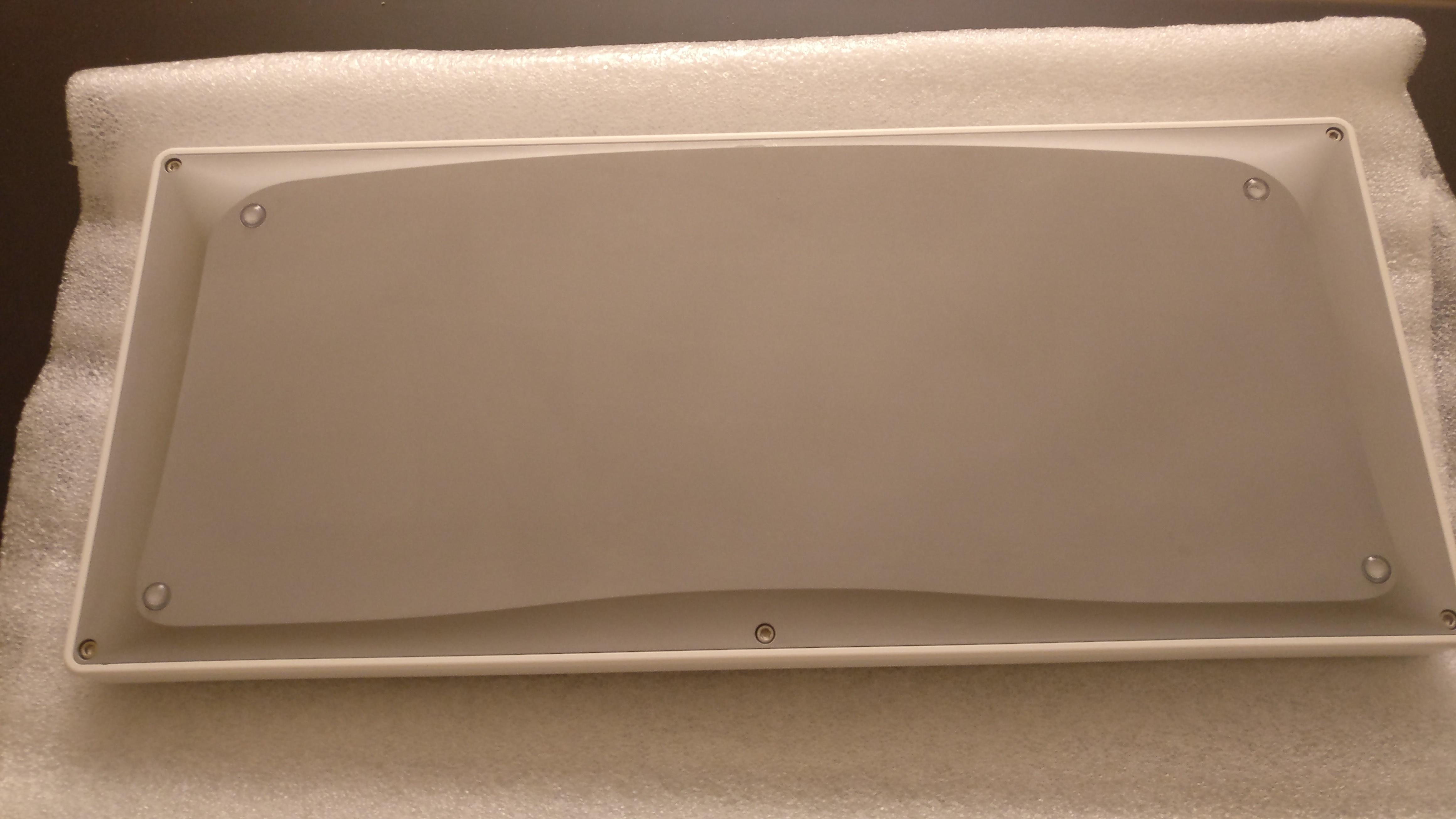
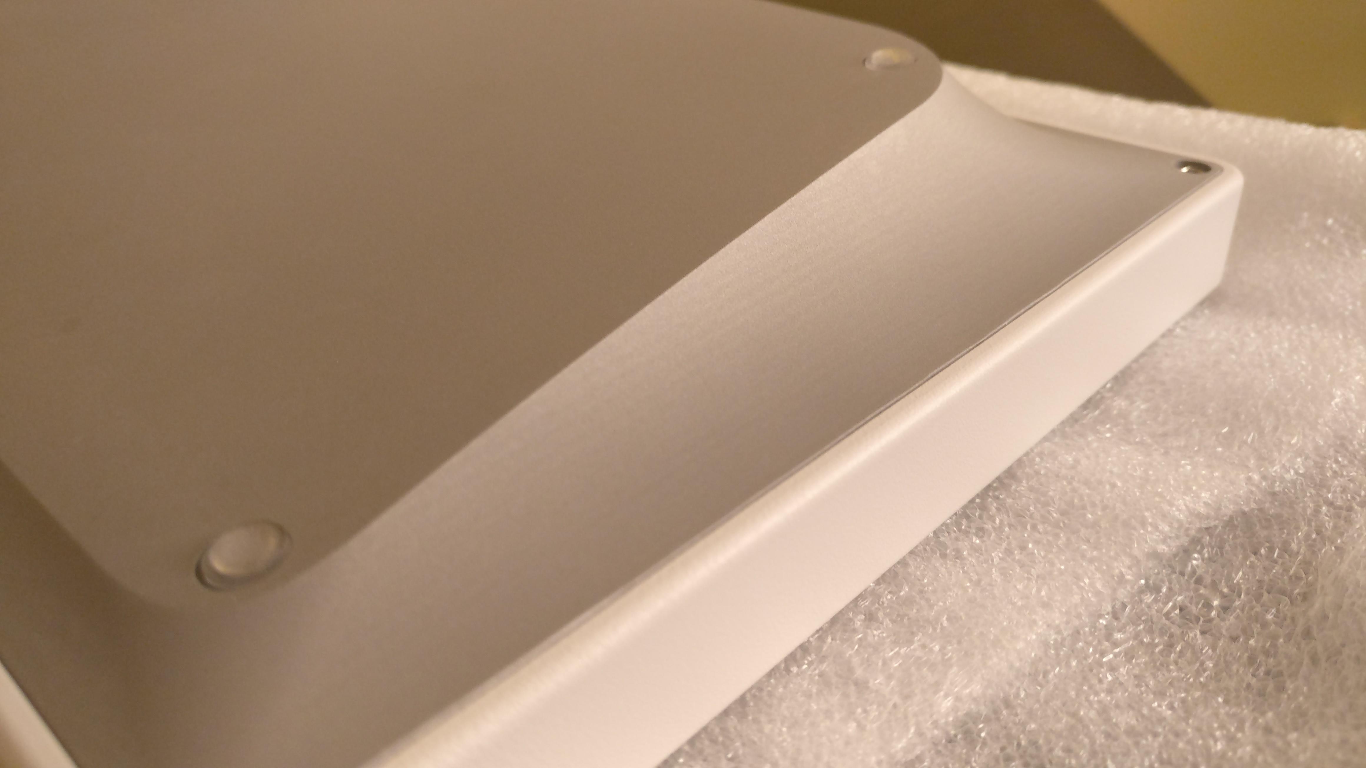
If you look carefully on the second image you can see the remaining CNC machining marks due to the stepping passes to machine the curby sides.
I could have asked for a better finish of course but it would require more steps and the machining time would have significantly increased (and so the price).
Also if you look at the direction of the milling traces, parallel to the the bottom side, you will see that a straight up 3 axis machine has been used for the process: I’m happy to see they didn’t used a 5 axis machine as the design goal was to be easily machined on a 3 axis one.
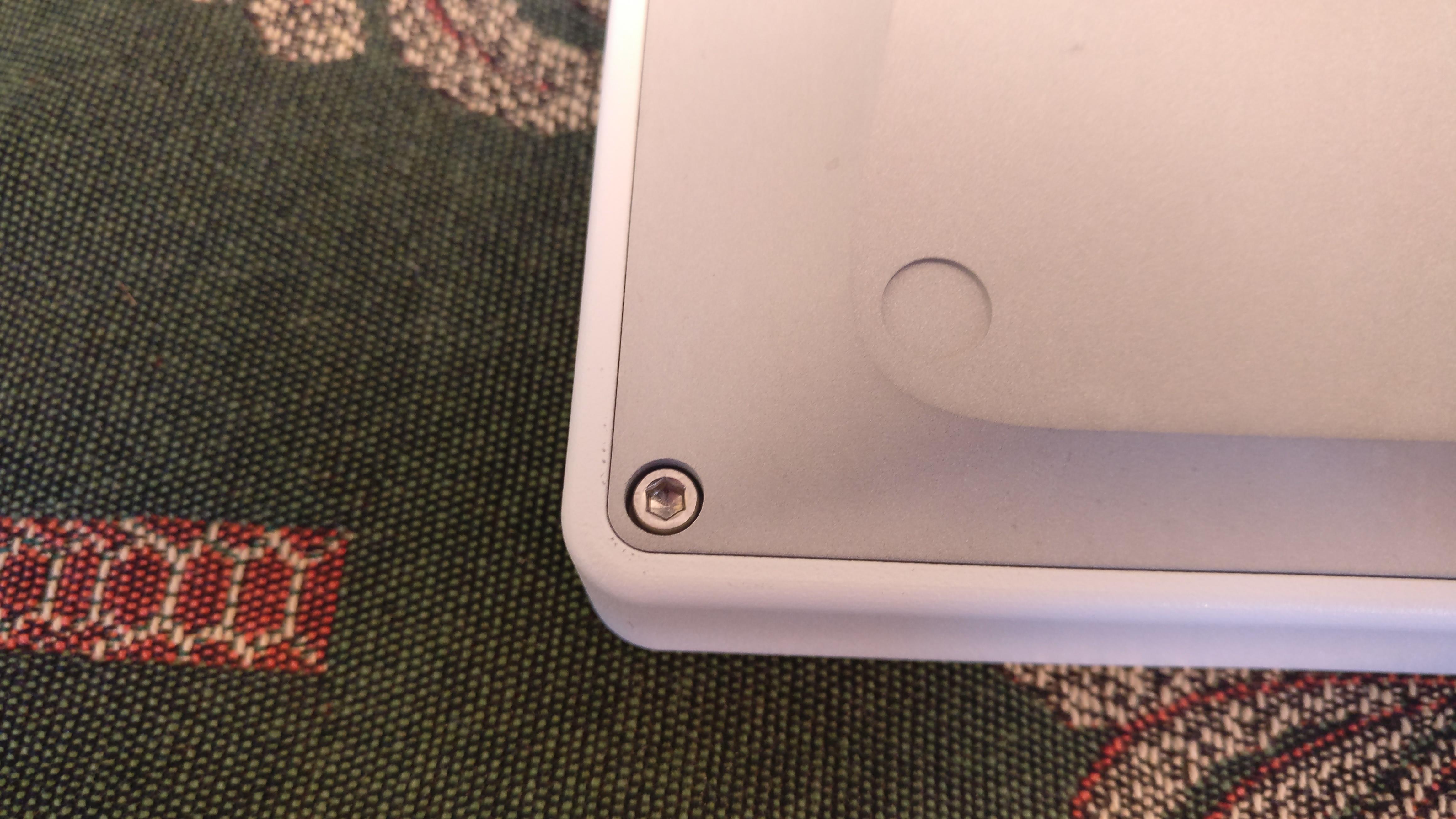
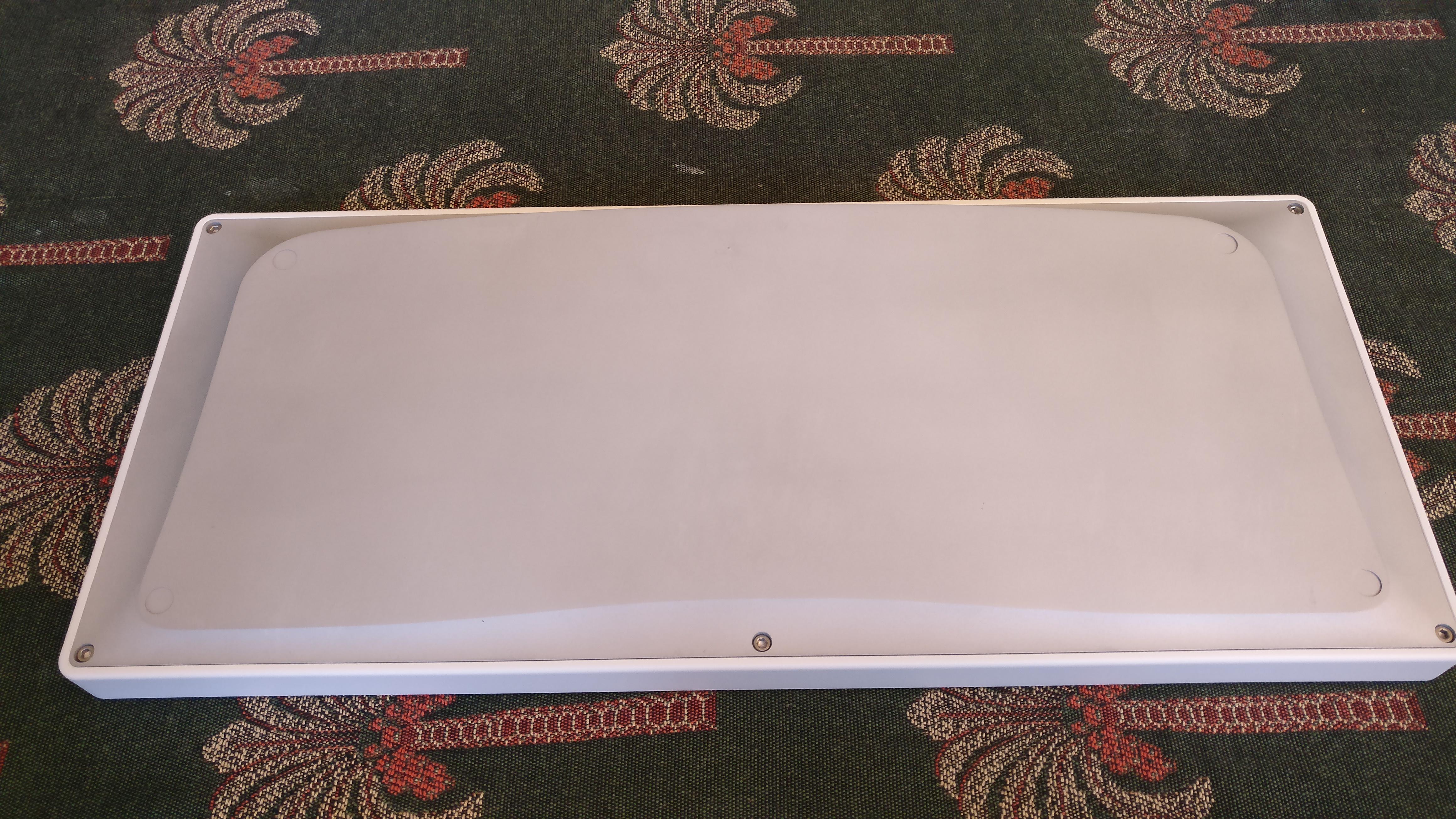
The last two bottoms , both copper and aluminium, have been mirrorred polished on the sides and brushed on the flat surface.
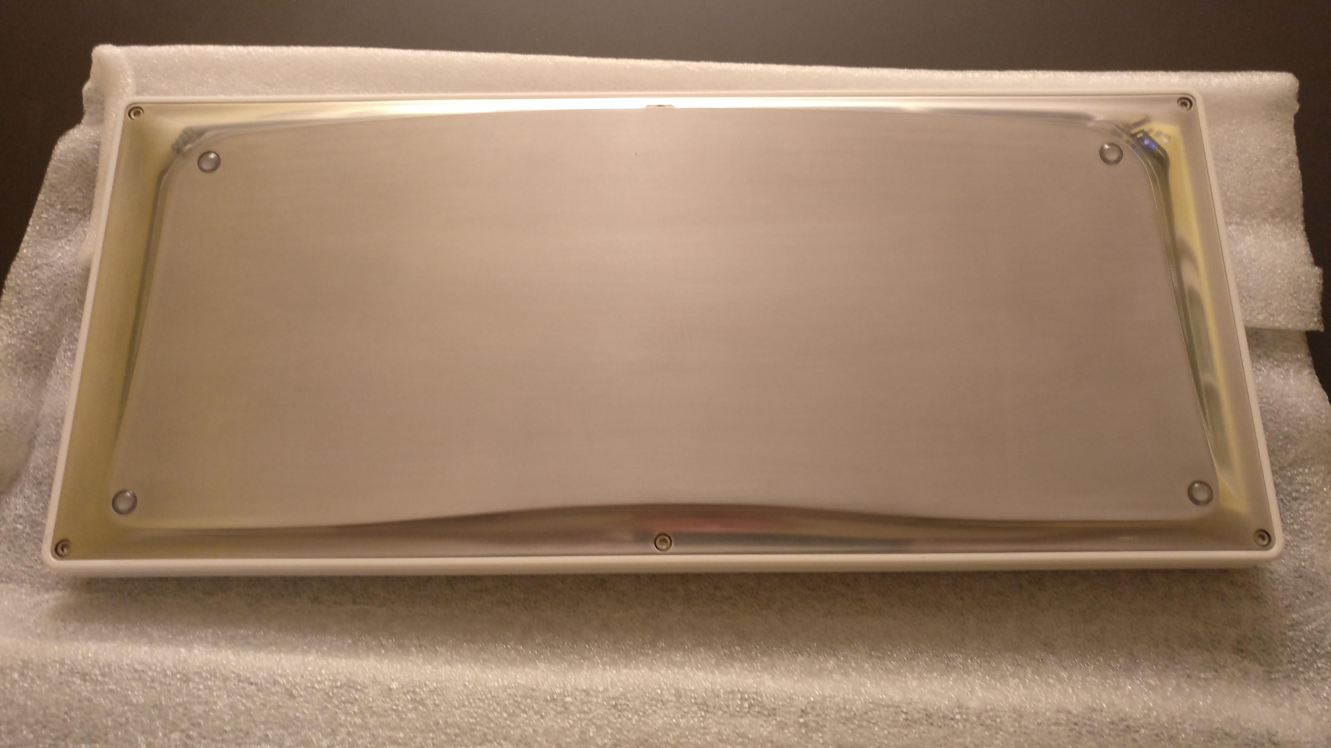
All four boards ready for assembly!
12 Likes
Lovely
1 Like
Absolutly.
1 Like
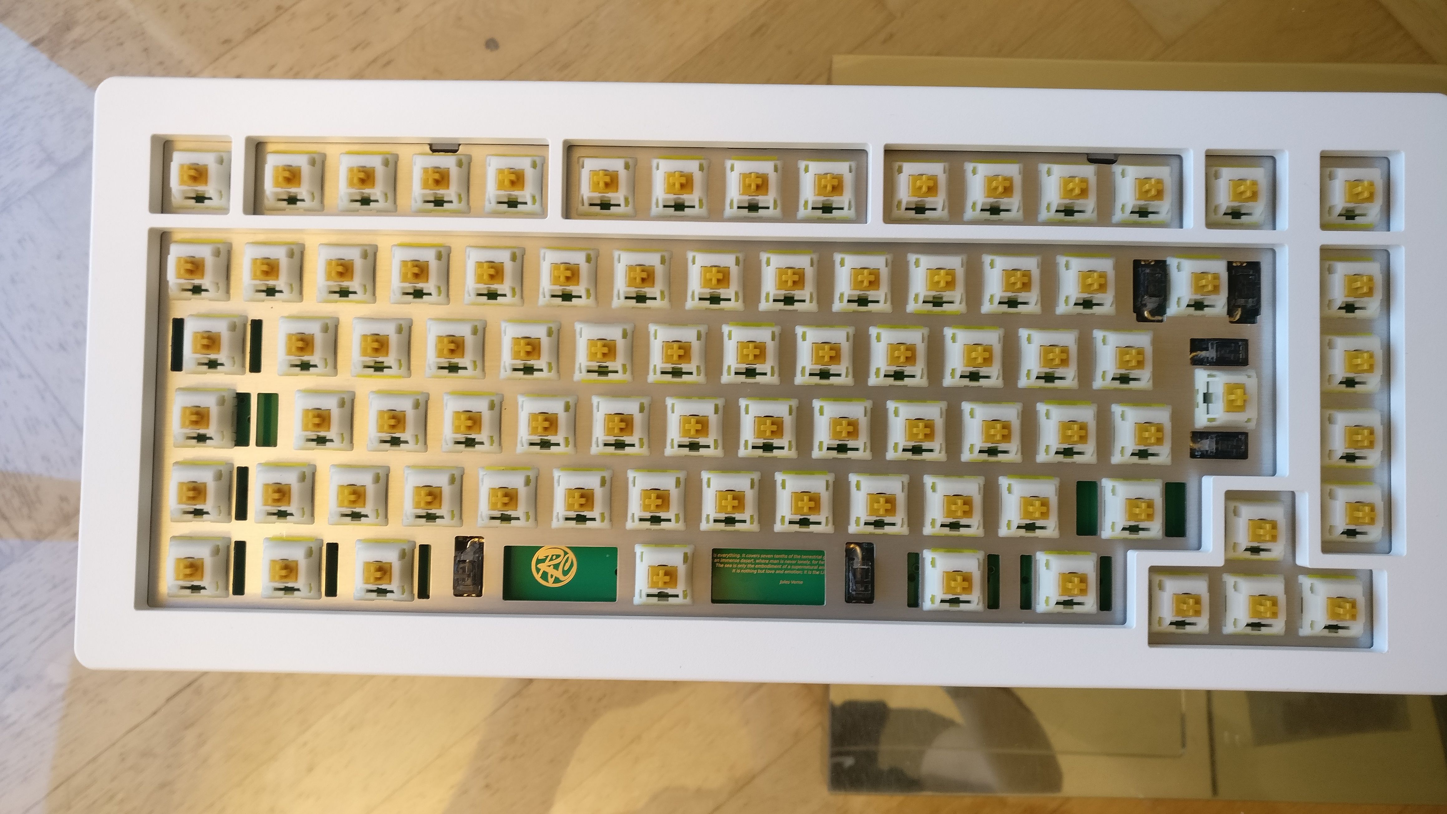
Hello guys,
Had some time to assemble two boards this week, so here we go for some some lengthy text and crappy shots
First was an experimentation on the placement of the poron strips inside the grooves.
During the design I’ve intentionally made them very wide.
This in order to allow experimentation with:
- Poron type (only 3mm poron XRD tested so far).
- Poron strip length (mine are roughly 1.5 cm).
- Poron strip placement.
The strips have been roughly cut to shape with a sharpie and scisssors and stay in place by friction.
No need for adhesive for them to stay in place, this was also my goal for ease of experimentation, I wanted this board to be very hackable.
Of course I’ve tested without poron, and it is perfectly acceptable is you want a super bouncy feeling.
First placement has been in the middle of the grooves.
This keeps a good amount of the bounce while not stiffening the whole thing by much:
But I finally preferred when the strips were placed at the very end of the leaves.
This a bit stiffer, but dampens vibrations much better:
Here is a photo with the plate assembled with the strips placed in the center of the groove, as said this method has not been kept for my daily use but it is a matter of preference:
The board have been designed with aluminium plates in mind for the flex, but I think that FR4 plates could also work well, so should be carbon fiber for a stiffer feel.
There is so much to test on this board (that I will probably not do because what I have is to my taste).
The feeling is what I had expected with the porons: moderate flex and good vibration dampening. This makes for a very comfy typing experience.
For information on switches I used Gateron Inks v2 lubed on the stems only, filmed and spring swapped with TX 60g long springs.
As for the sound, it has been a pleasant surprise for me.
This is kind of hard to describe but I’d say a dense creamy sound.
This reminded me some sound captures of the Jelly Epoch or other PE foam modded boards I previously heard, but I could be very well wrong.
I love this sound
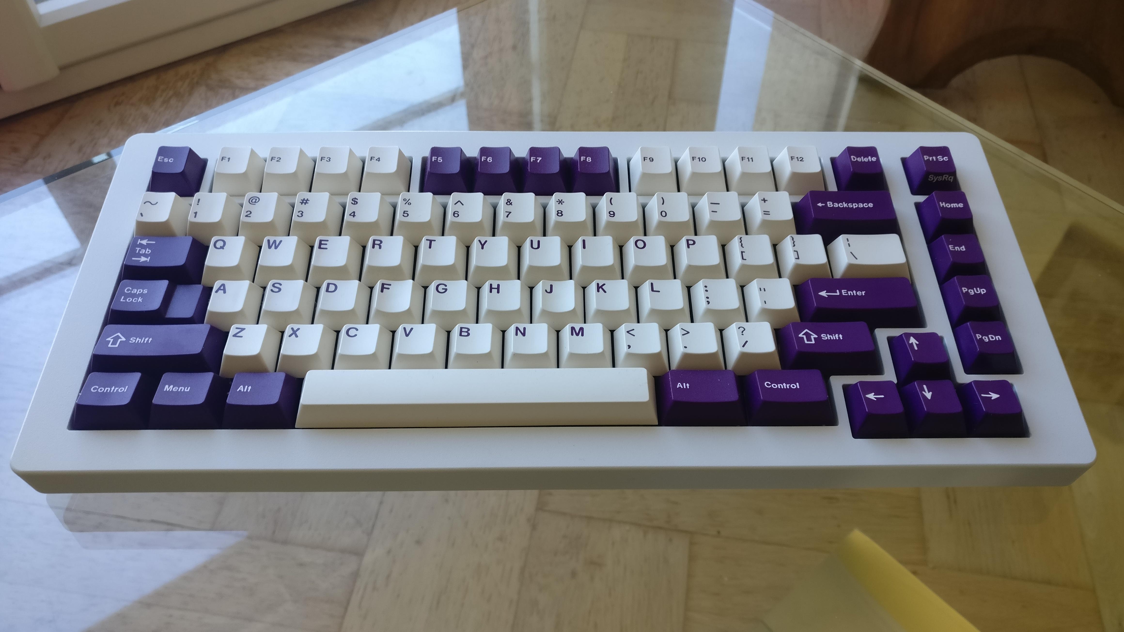
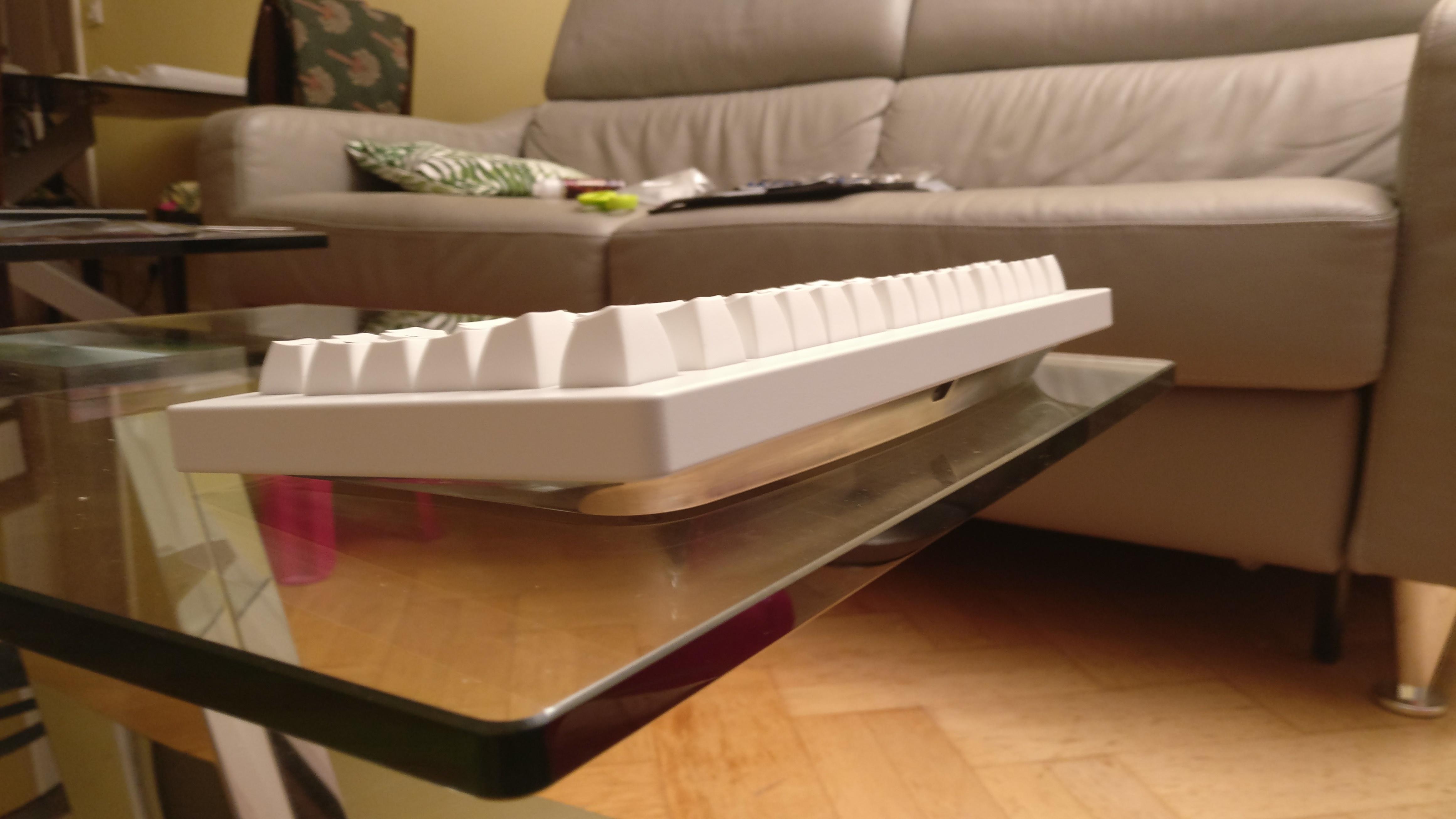
Here is the board assembled and ready to work (and play) with:
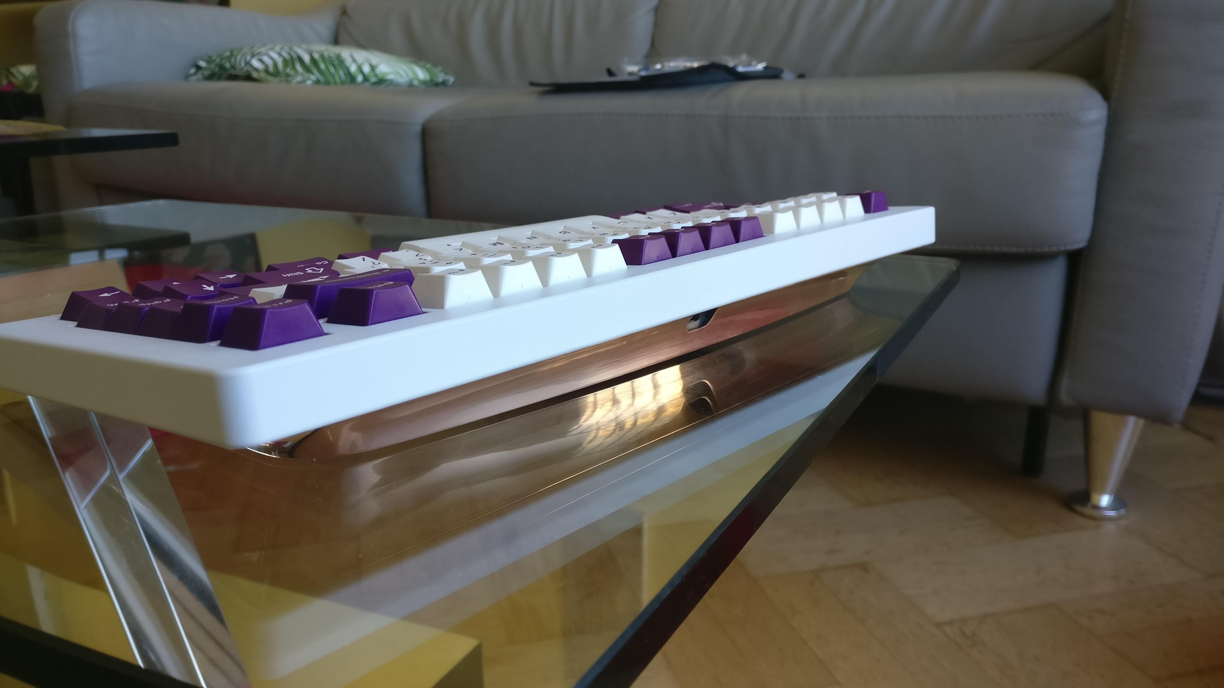
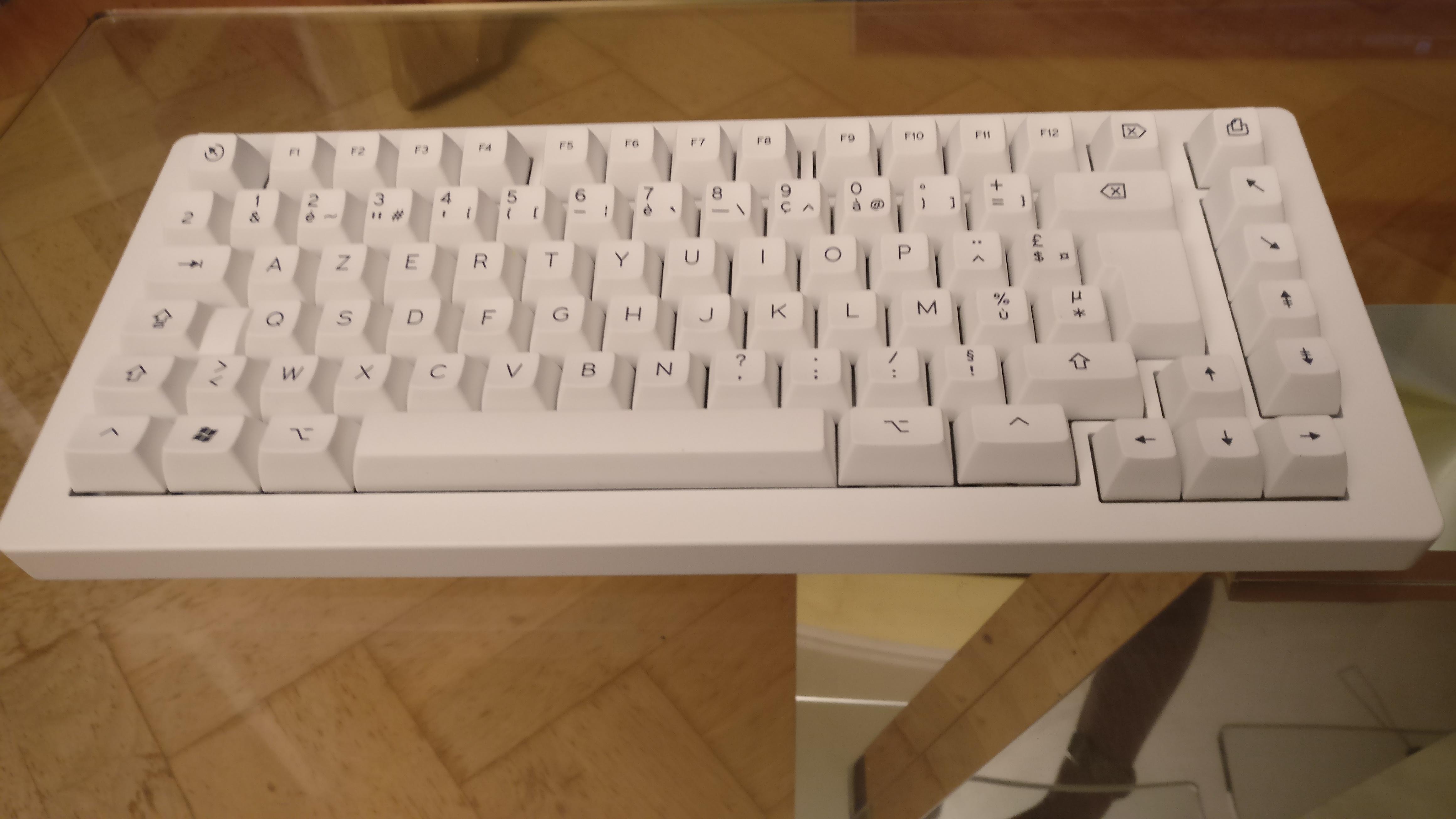
I did also assembled the aluminum polished board, this time with U4T tactiles and high profile keycaps (SA-P AZERTY keycaps from Signature Plastics).
In term of sound it is a totally different beast, as high profile keycaps makes the sound significantly lower piched and noisier (for the noise the tactile long poles switches do a lot).
See you
13 Likes
The White on White is so beautiful.
1 Like
I like it quite a lot also.
Probably because the WAN color of the SA-P keycaps is very close to the RAL 9010 color used for powder coating the top case.
Hello all,
I am pleased to announce that The Manta75 keyboard is now available as an opensource project !
Everything is available at the following Gihub link:
Your are free to have a look (any feedback appreciated), take any inspiration you’d like, and even make your own board if you want!
Greetings,
Rico
6 Likes
This is amazing work, thanks for making this available Rico! It was fun following this thread the past year+, and the board turned out very nice.
1 Like
Thank you for making this open sourced! I love this project and have spoken to you about it a few times
One thing that peaked my curiosity was the GitHub comment regarding the color:
That is really cool I thought the green was off from your photos due to your camera not because it was actually a different color. What settings did you manipulate to do this? (I downloaded the KiCad but couldn’t find anything different it in the board setup or Copper Zone Properties vs PCBs I have had made)
(I am considering building one Q2 or Q3 maybe out of wood this year depending on other projects.)
1 Like
Thank you for the nice feedback !
Most of the solder mask colors are not truly opaque so the final color will depend on what is below it.
If there is copper on the same layer the color will appear brighter.
If there is no copper on the same layer and copper on the opposite layer the final color will be darker:
- grayish white for white.
- dark green for green.
- dark red for red.
- …
This technique is commonly used in PCB art were people create convincing images with 2 layer PCBs, by creating new colors out of just FR4 transparency, solder mask and copper.
You can have an idea of the final result in Kicad on the PCB render view.
1 Like
Super cool sounds like something I might join in on. Any thoughts on price point?
1 Like