The Winghead, a new personal keyboard project

This weekend I had two correlated objectives:

  • Test if the switch matrix is working as intended, and try some workaround if not.
  • Write a QMK firmware.

As with the first objective I encountered a quite a lot of problems.
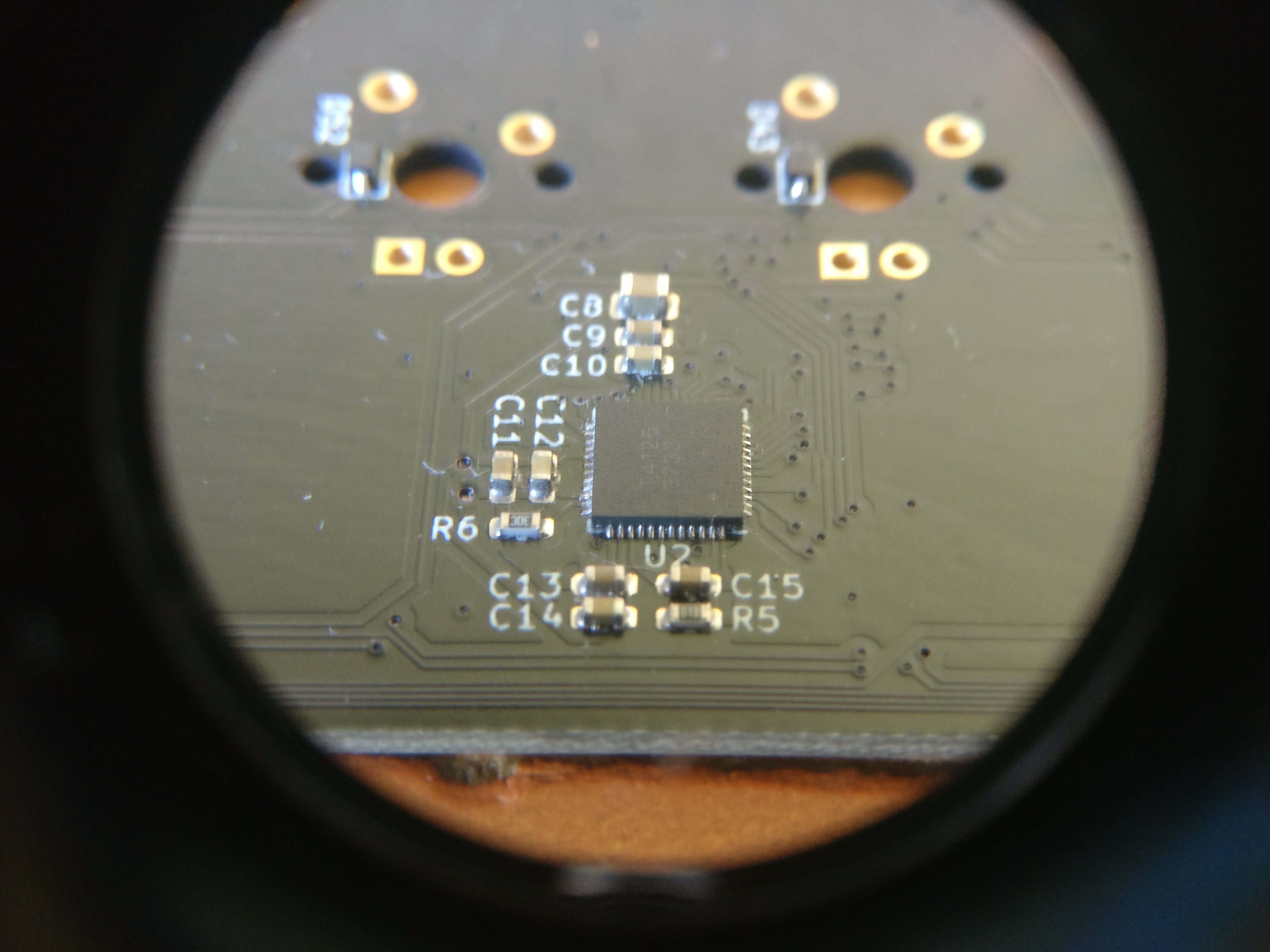
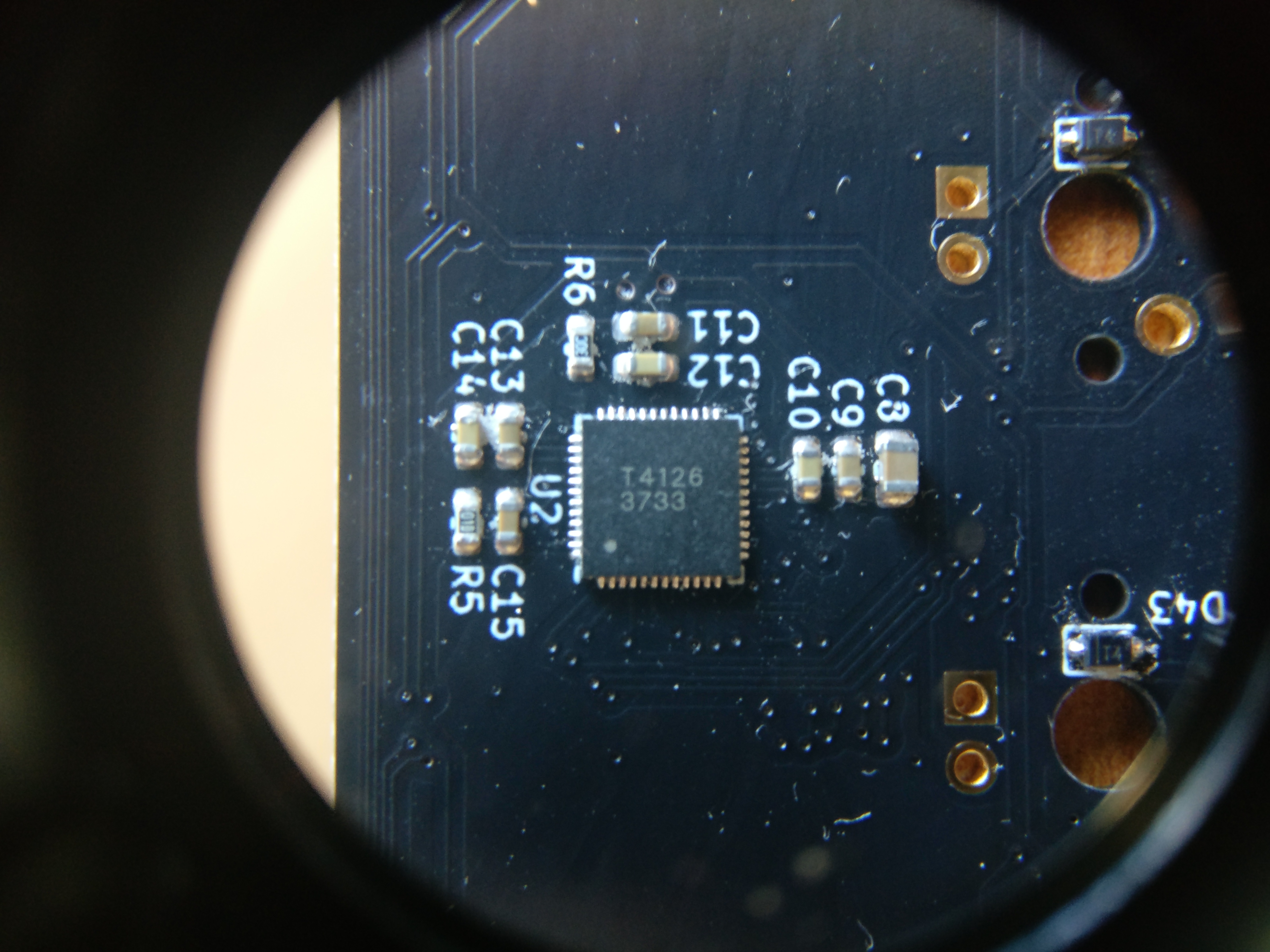
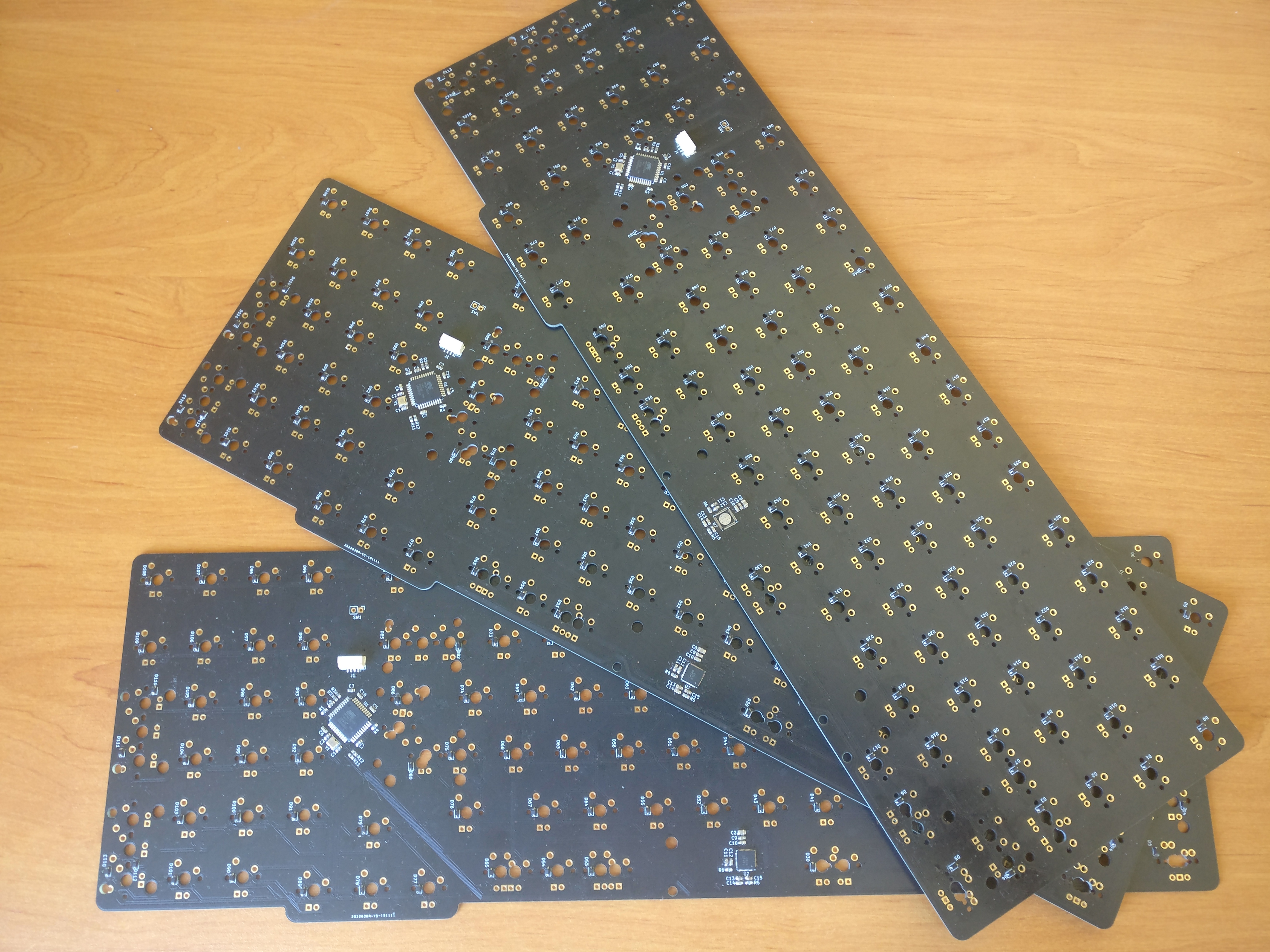
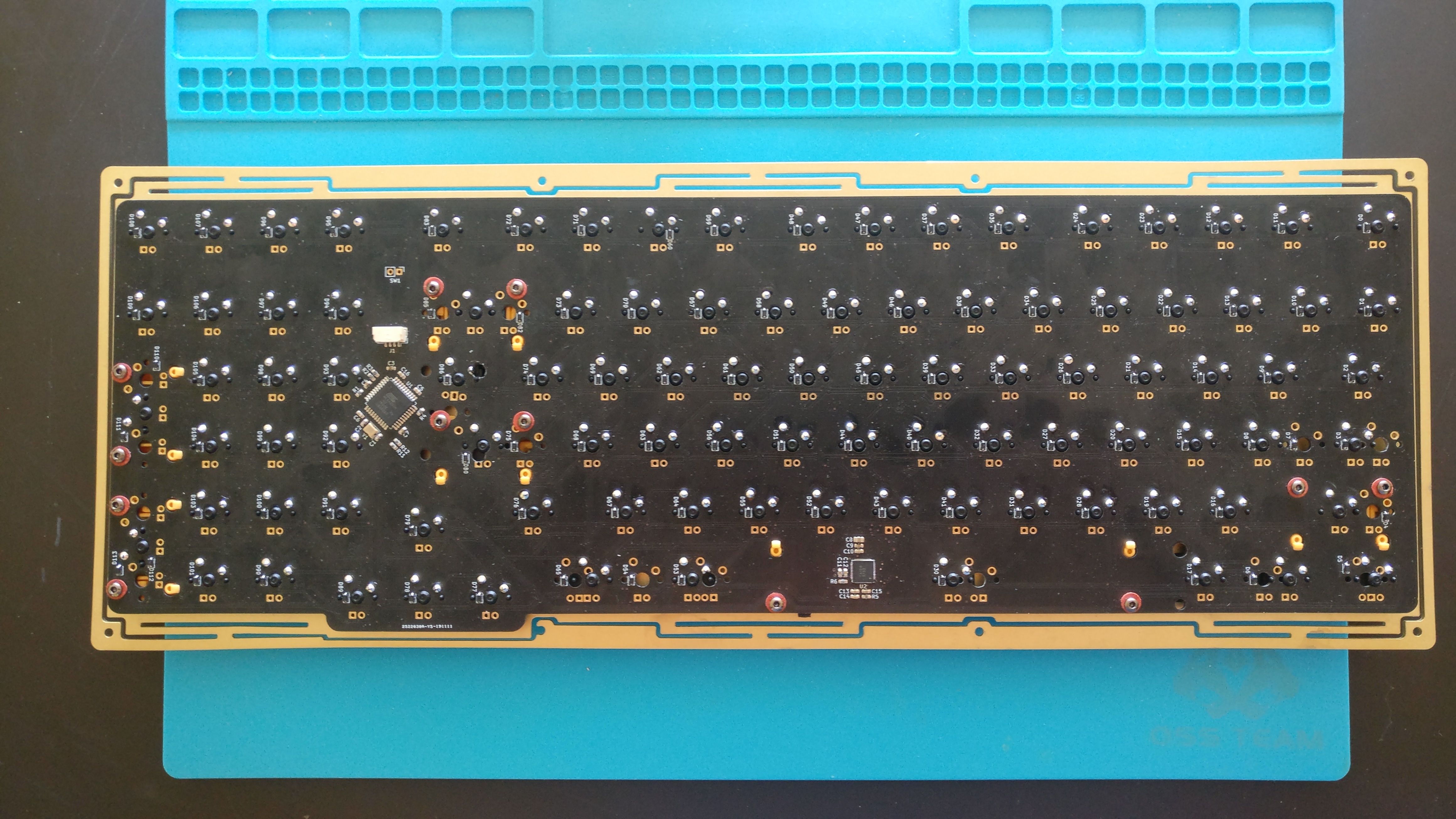
First, some diodes were not fully soldered and seven switches were not working as a result.
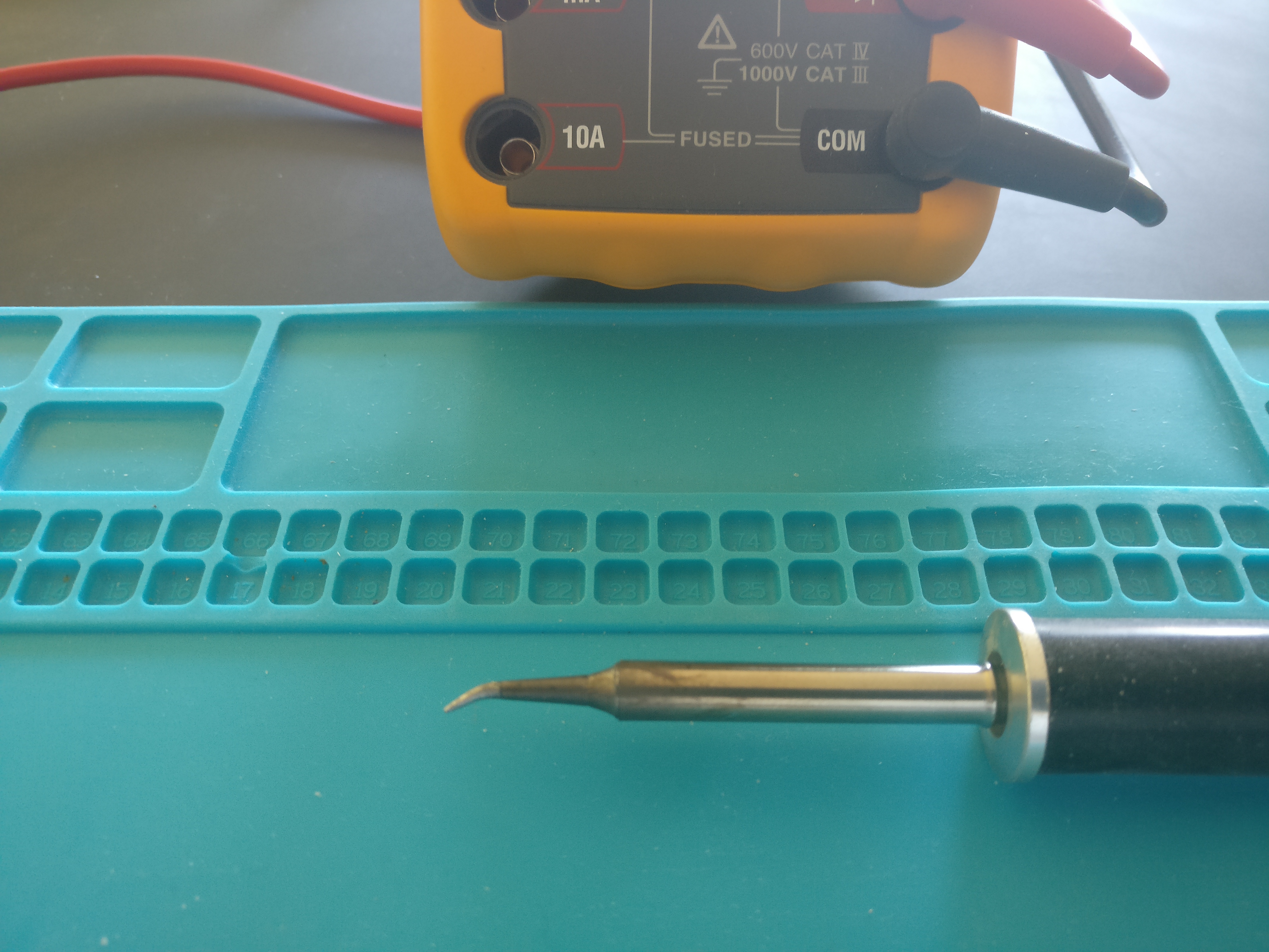
Had to track down every problem with a multimeter and resolder these diodes by hand.
The pads of these SOD323 diodes are extremely small and this made this task a challenge.
Next time I’ll either switch to a 603 footprint or SOD323 bigger footprints for hand soldering purposes.

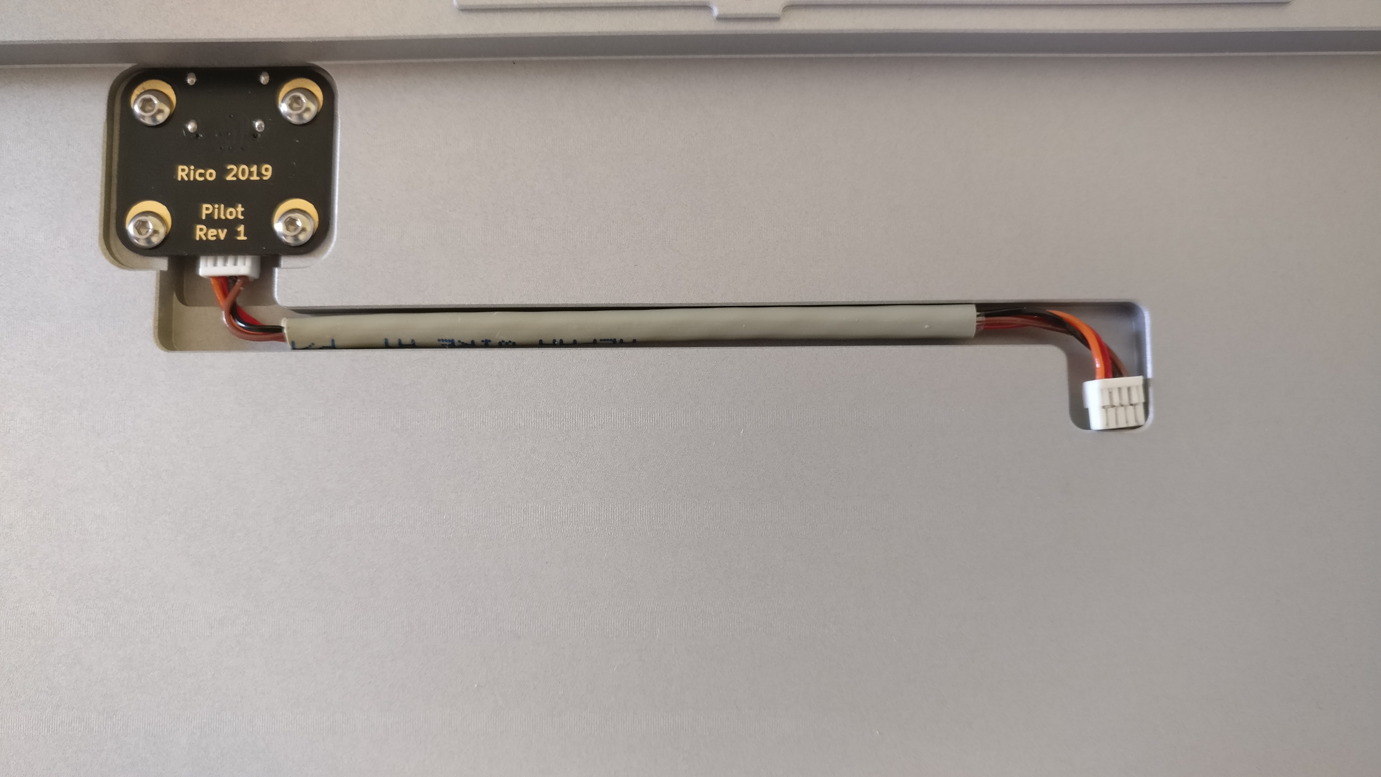
Second problem, the home made cable connecting the USB daughter board to the main board had a broken wire; depending on the orientation the wire was making contact to the header or not.
This drived me nuts …
Remember when I had trouble making the keyboard recognized last time? That was the reason :rage:
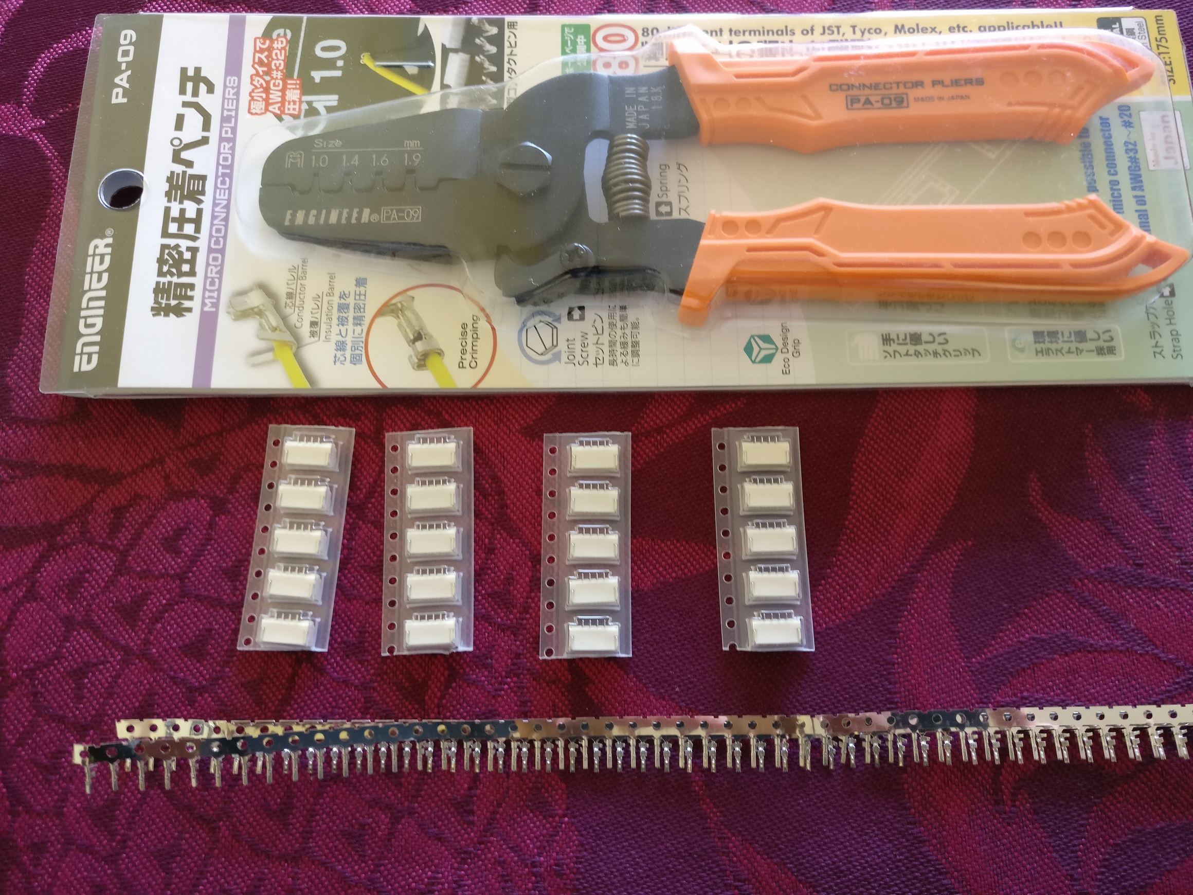
Re-attaching a new crimp to the wire and it was good to go.
If you are curious, here is the hardware needed to do a JST cable yourself.

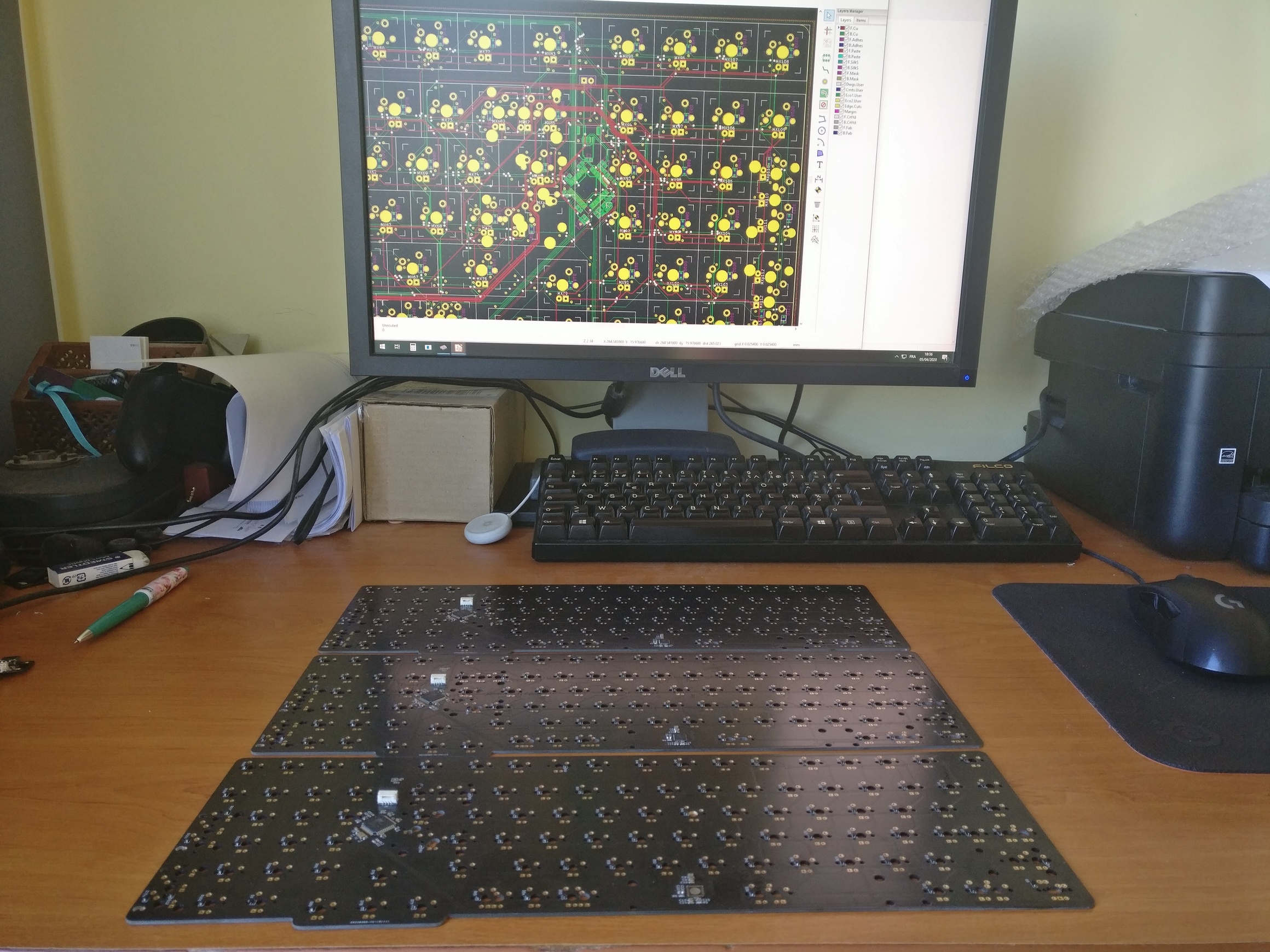
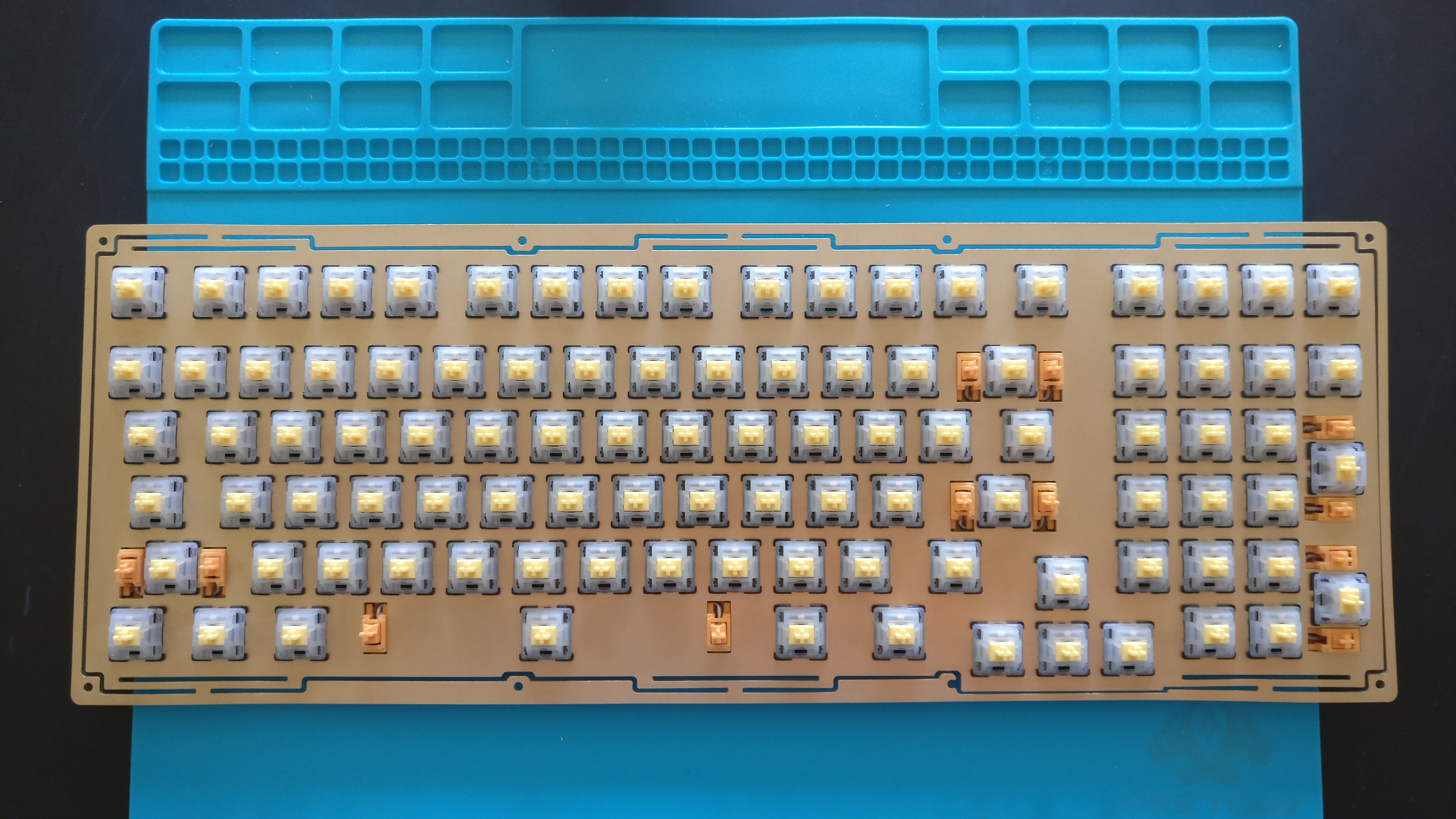
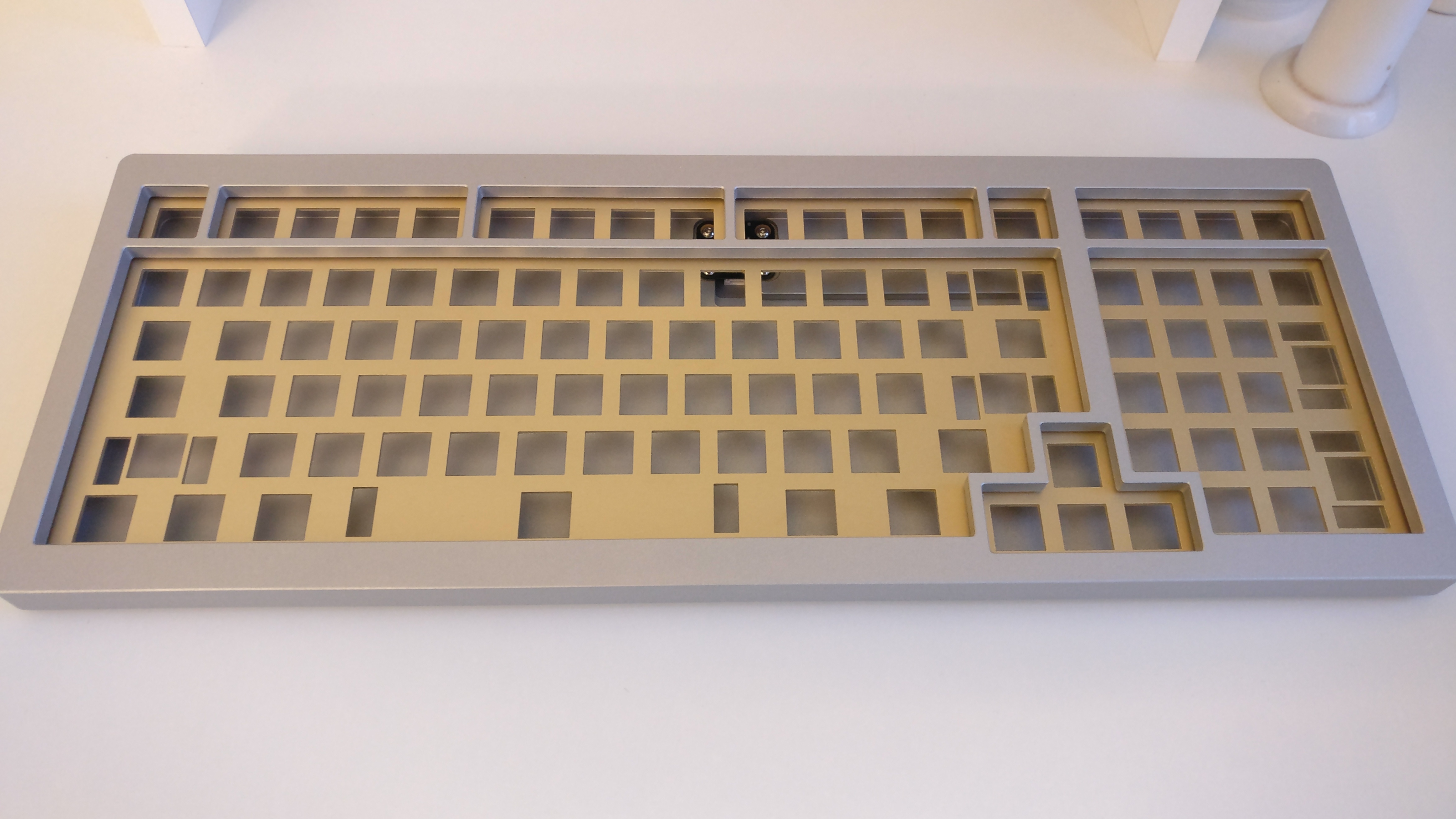
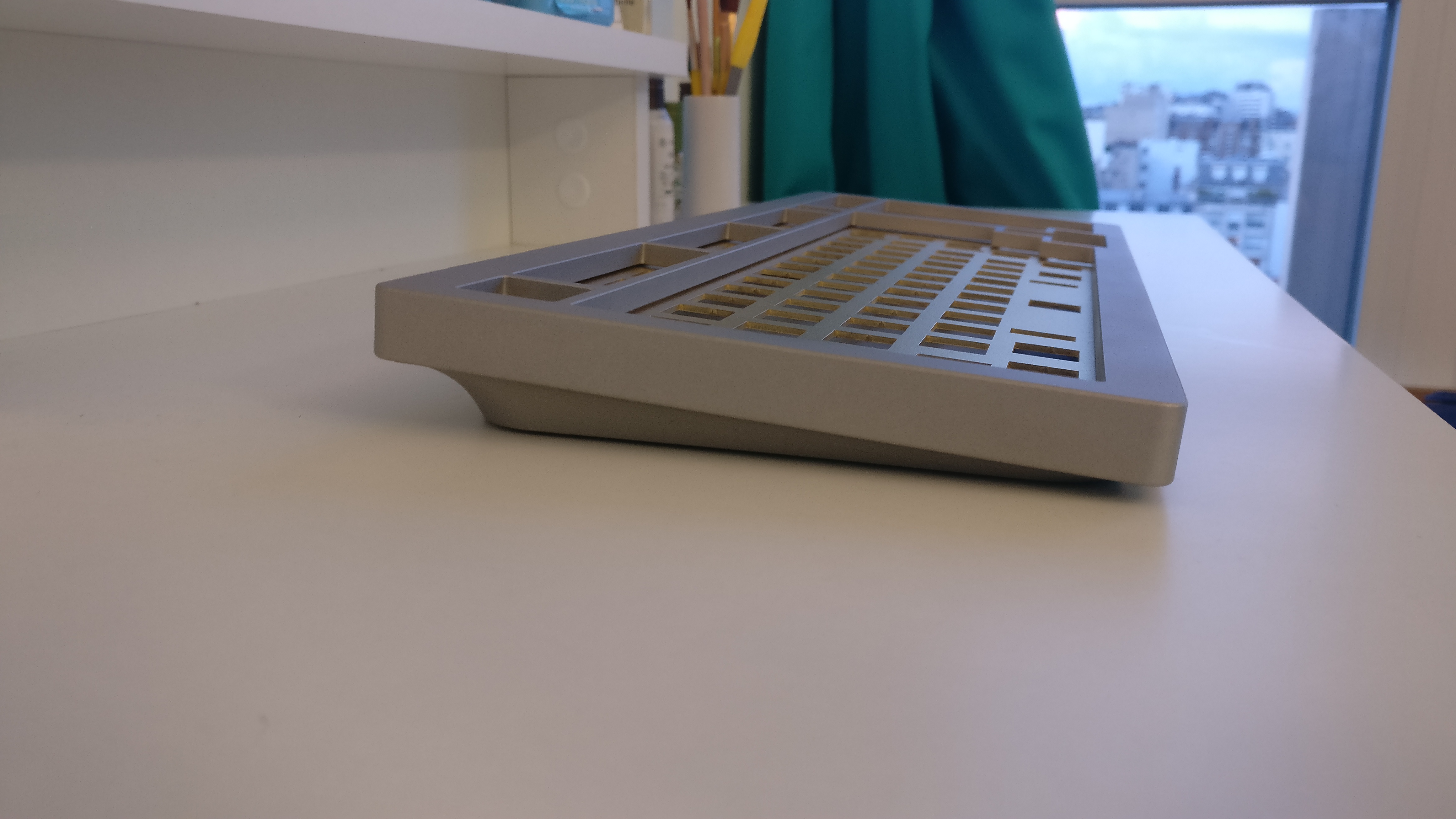
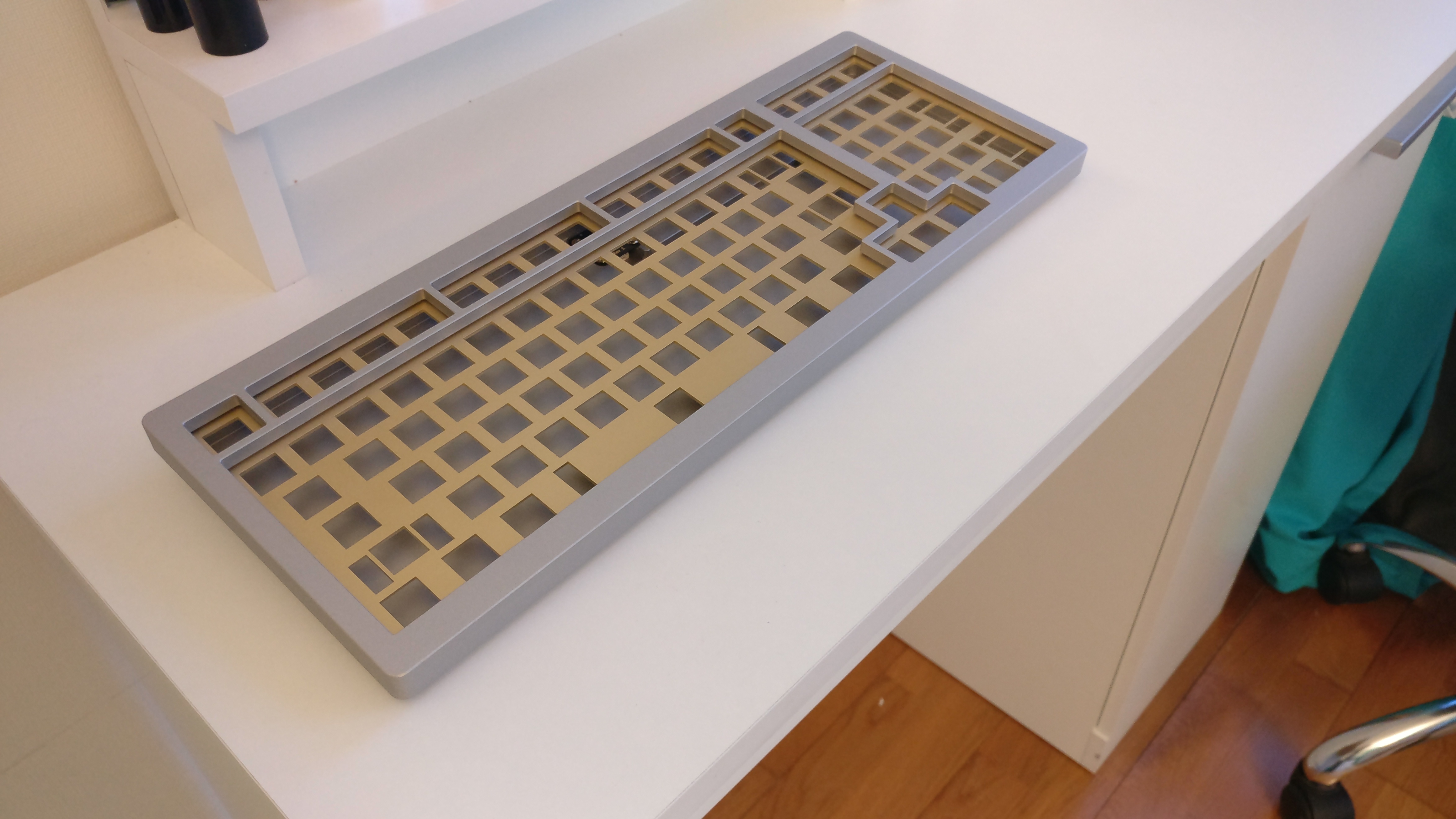
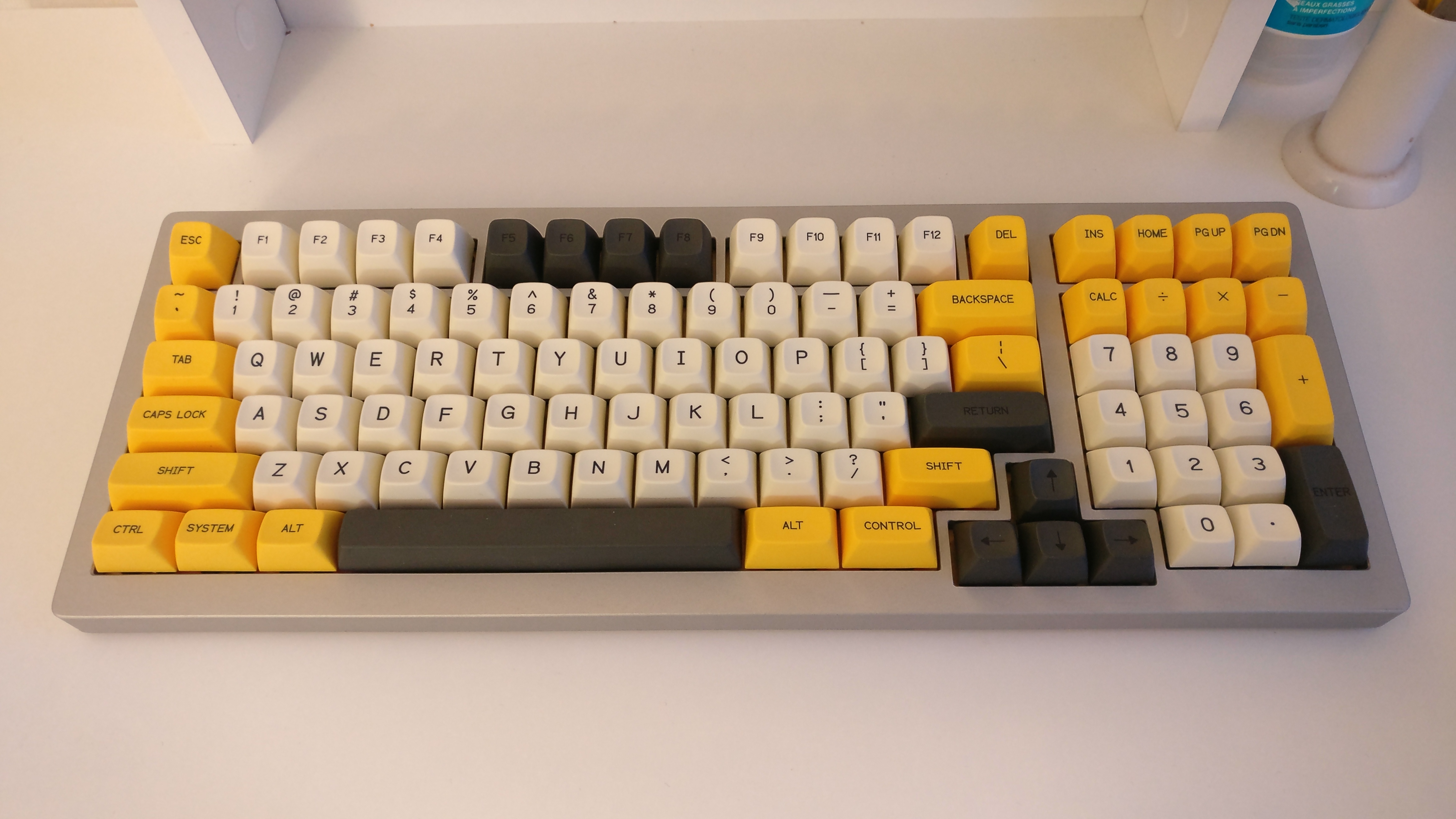
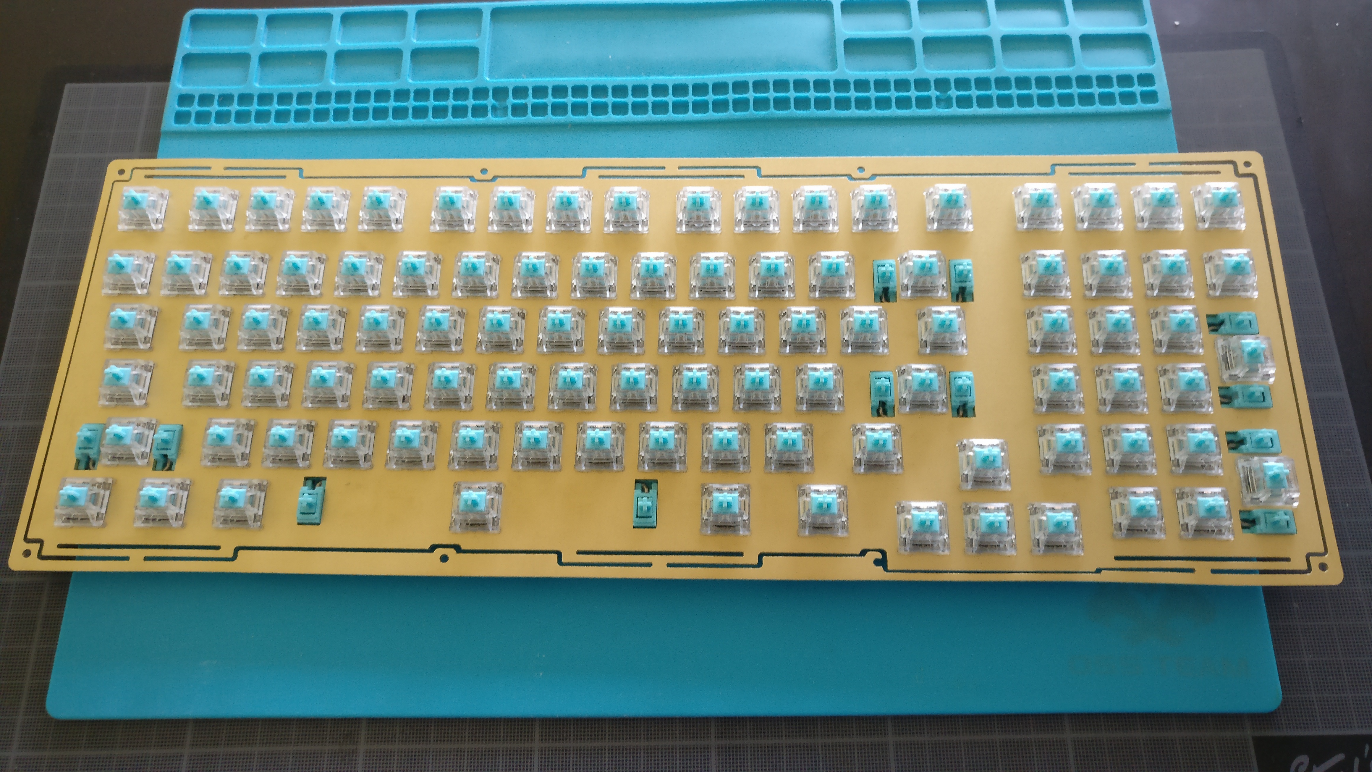
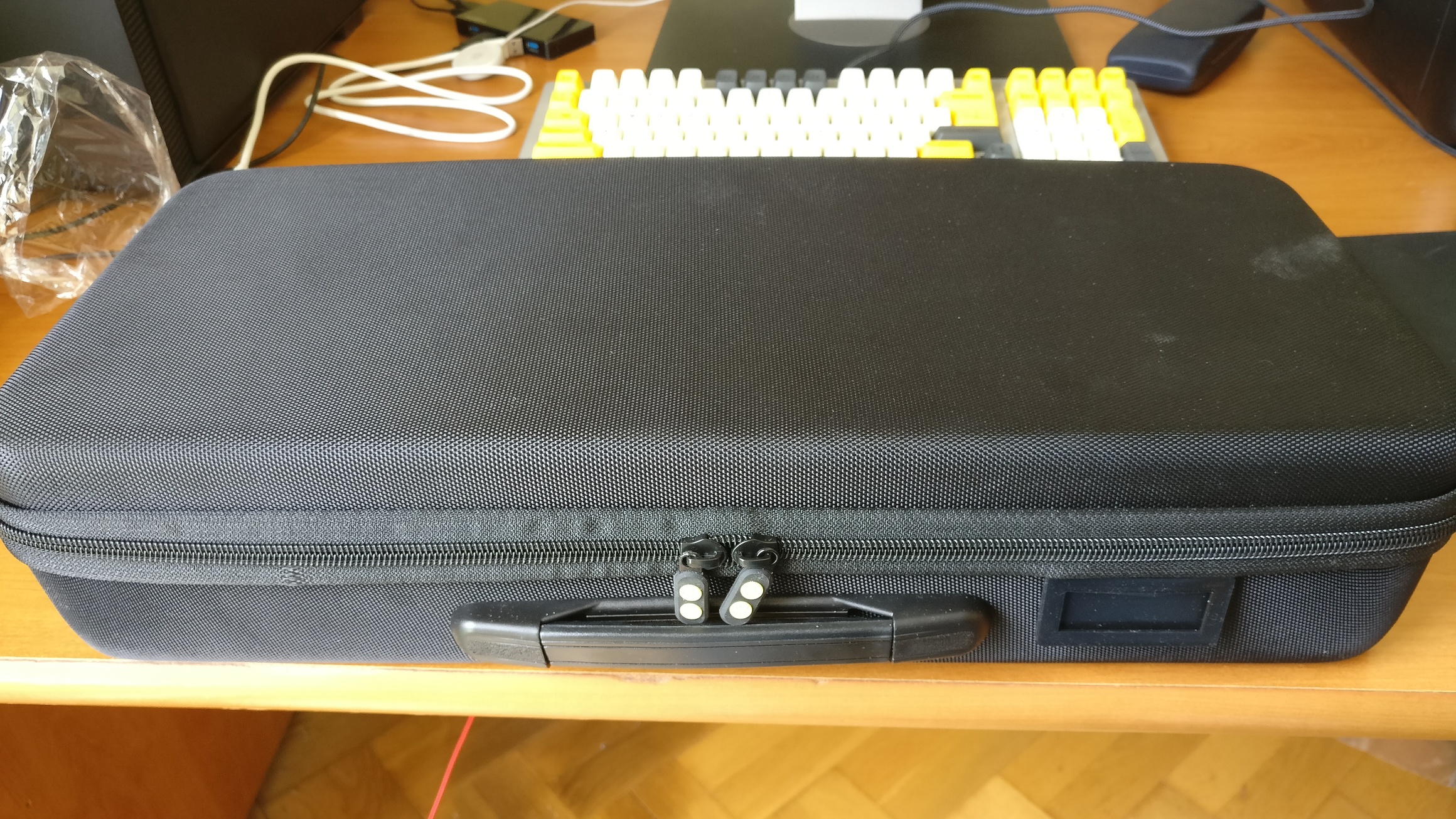
I could finally validate that the PCB was usable and it is a great news :slight_smile:
Is it perfect ?
Certainly not:

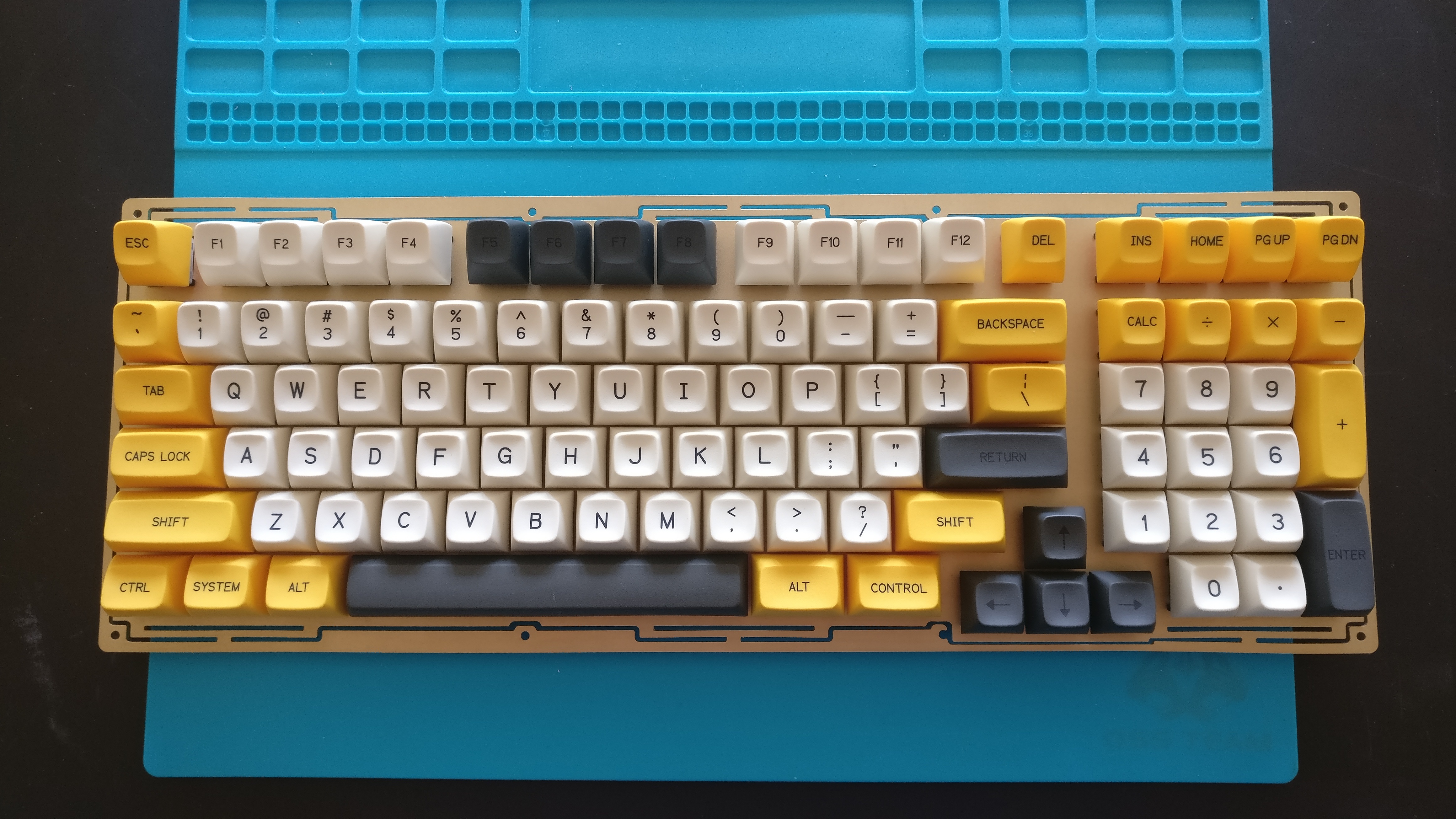
  • ‘O’ and ‘0’ footprints were inverted during placement on the PCB.
  • Stepped Capslock footprint is placed wrong, I will have to do without…
  • The 2 1U keys that can replace numpad + and enter are wired wrong, not a big deal.

Overall it could be much worse, having something unusable, and I’m happy of these results on the first revision of the PCB.

And now the QMK firmware.
I wanted to try VIA as it can now be used without restrictions and what a great piece software!
It is very nice and easy to use, so much more convenient, a big thank you to @olivia and @Wilba and the others that I may have forgot !

If you want to port a keyboard to VIA, I strongly recommend the following links.

  1. VIA documentation, it explains everything including configuring QMK source code
    https://caniusevia.com/docs/configuring_qmk
  2. Have a look on @merlin great videos explaining how it does, it is very self-explanatory.

KLE is used to map keys to row/column and define layout options, to be exported later on in Json format for VIA software.
Here is the result on the Winghead:

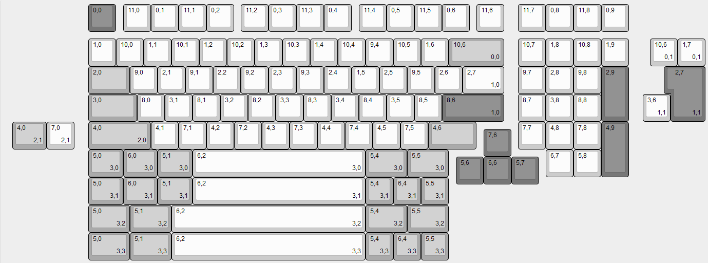
I discovered that doing that work on KLE makes you easily see the switch matrix topology, I saw that some of my switch row/colum placement could have been better.
Next time I’ll do that step before starting designing a switch matrix on Kicad.

After a few trial and errors I had the following result on VIA :slight_smile:

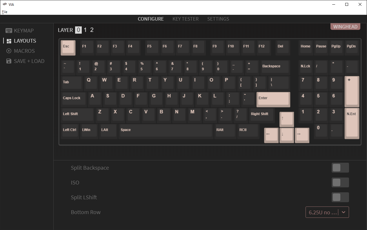
Next step, make a second PCB and find a way to solder the LED driver this time :wink:

2 Likes

I hope you are all sound and well in your respective countries.

As anybody who is confined due to Covid19 I tried to fill my last two weekends with stuff to do in order not to get bored.
So started lubing switches: my Gat Yellows are 205go lubed and filmed and started doing the same thing for Zilents v2 62g.

But also have to solder 2 other PCBs if I want to build three Wingheads.

And why not try to solder this tiny led driver this time ?
Let’s go!

The led driver is an IS31FL3733, 48 pins in a tiny 6x6mm QFN package.
This thing is a challenge to solder for an individual like me with no big equipment.
I’ll have to be creative :stuck_out_tongue:
I went with a mix of hot air and iron soldering techniques and exclusively used solder paste (no wide solder).
It may seem strange but in fact soldering tiny components with solder paste and an iron is very effective.

First step, place and solder the component on the PCB:

  • Applying solder paste only on the thermal pad (ground).
  • Carefully place the component and check alignment of chip and surrounding pads with 10x magnification.
  • Use hot air station with minimum air flow to not make the component move.
  • Check result.

Second step is to solder the surrounding pads:

  • Put a small amount of solder paste along the pads/pins.
  • Melt it with the iron using the drag soldering technique, taking care of making contact with the tip of both the chip pins and the PCB pads.
  • Re-check.
    And the result:


I needed a fine tip for that, used this thing below.
Also soldered all diodes by hand for the third PCB with the very same tip, this worked wonderfully.

And now have 3 working PCBs and 2 that have this led driver soldered :slight_smile:
I don’t know yet if the led driver will work as intended (need to work on the QMK firmware, and need leds), but at least without leds every keys are working as intended.

If confinement last longer than expected I may solder a fourth one with the led driver :smiley:

5 Likes

Hey dude, nice! It looks like you’ve got a microscope of some sort to check if you have shorts, so you ought to be set. My strategy for doing something that small would probably be paste on the ground pad in the middle, set the chip on and hit with the heat, and then put a lot of solder on the tip of the iron and basically just drag it along the sides, you’d be surprised how well that can work. It looks like you already got them down though!

1 Like

Thank you!

It’s not a microscope, but a 5$ 10X magnifier I put in front of my phone camera :stuck_out_tongue:

I basically did what yout said for the soldering job, at least for the ground pad.
Will try the drag soldering technique with wire solder next time for the sides and see how it works :wink:

I love seeing this progress update by update :slight_smile:
It’s always inspiring and motivating to see someone continually work on an awesome project bit by bit in this adventure!

1 Like

Thank you for the kind words !

I can still make 2 additional PCBs and need to figure out what to do to make led lighing work on QMK.
This will probably fill my next 2 weekends :stuck_out_tongue:

Then to go further I will need to have the cases to be manufactured, but as everybody knows the current situation makes this step complicated and I’ll have to be patient :wink:

I could spend some time on the project this weekend.

The goal has been to validate correct fitment of all the parts excluding the case.

Here are the parts used:

  • Brass plaste cut at Laserboost:
    • specific to the layout I want.
    • no visible holes after stabs and switches installation.
  • Gateron Yellows milky top:
    • only variant in stock at that time, no transparent PC.
    • as @Walkerstop said in one of these videos, supposedly a bit more scratchier without lube but sound is a bit deepier.
    • lubed only spring and stem (with 205g0) as @jshufelt found in his numerous builds that it already gives very good results.
  • filmed to reduce top wobble.
  • Yellow C3 stabilizers, lubed with Superlube.

This will be a Yellow build, hope you’ll like it @Rob27shred :stuck_out_tongue:

The brass plate was giving a significant amount of ping when taping on it.
The amount of ping would probably be reduced when all switches would be soldered on but I hate pinging noise so I took no risk and went with the sorbothane struds approach that @jshufelt used on many of his builds.
I tried to solve my own way some of the problems he found: the available sorbothane thickness is either 3mm (no contact with both plate and PCB) or 5mm (too thick).
I added a layer of 1.5ish mm soft eva foam double taped on top of the 3mm of sorbothane.
The result is not pretty but a perfect height and softness combination.


For the plate design I used AIO3 plate generator and saw that stabs fitment was VERY tight and was worried of not beeing able to fit everything together.
Also used AIO3 designs for the MX pcb footprints and saw that I needed to force a little bit on the switch to make the plastic pins slide through the PCB.
Thankfully none of these concerns have been a problem, moreover having a bit of insertion force between switch and PCB could maintain sorbo struds compressed, making my soldering job a breeze.

Just to show you the level of tightness on the stabs openings:

Easy soldering:

Yellow POWA! from the top:

Just received my MT3 Serika keycaps, those are gorgeous!
You want even more Yellow ?

My findings during this build:

  • AIO3, this man definitely know what it is doing when designing keyboard things :wink:
  • Gat Yellows are already very smooth out of the box and to my mind don’t really need lubing for the smoothness, but you need to lube the spring to reduce pinging noise and lubing also silences the upstroke significantly, so to lube you need in the end …
  • The sorbo strud treatment was impressively effective: you go from a ‘ding’ to a ‘thock’ noise. And as @jshufelt found you only need very little to do a fantastic job, thank you man !
  • I heard problems of PBT keycaps use (ePBT) with C3 stabs, but I had no problem with MT3 Serika keycaps (also PBT); the black space bar I used was straight but both the white ones I have in the set are warped and may have caused the problem. I’ll see what I can do to later fix them.

Now this board needs a case … but given the Covid situation I will have to be VERY patient.

4 Likes

Hello keeb lovers,

No new images this time but a new achievement done today: after a very long meditation time and 3D model tuning work, I’ve settled on the CNC shop that will manufacture the cases.

Case finish have been decided and big money spent to the manufacturer (outch).

Now the waiting game starts again, but will definitely be shorter than for a new keycap set :stuck_out_tongue:
I’m expecting to receive my precious in a few weeks or so, like end of June or early July.
I’m eagerly waiting to see the final result, so excited :smiley:

4 Likes

Can’t wait to see how it turnes out!

1 Like

This is seriously awesome stuff. Keep us in the loop as it all comes together! I’m working on my own 100% custom build too!

1 Like

Oh, you will have a lot of fun :smiley:

Hello guys,

The magic package finally arrived today and I could not resist to open it to check what’s inside :stuck_out_tongue:

Here are the (many) potato pics of the thing:


The anodization is much better than what has been done on the Simply96 (I changed the manufacturer).

But obviously there are still some flaws, some (small) machining mistakes made by the manufacturer and others that are due to design decisions that made the case difficult to accurately machine.
You will have a hard time to see them in the pictures, but still it is definitively not Keycult like quality :wink:
Still so much to learn but better than last design and I learned a lot of things in the process; the next one will be better I’m pretty sure :grin:

I was relieved to see that the fitment test with every parts were ok, I will not have 5Kg of useless aluminium chunks in my appartment and will have my 3 working keyboards in the end.

As for the plate stiffness with the leaf spring design, it is a rather firm typing experience (witch I like) but still significantly softer than typing on a steel plate like on a Filco (a keyboard I have and that I can compare with): the plate definitely flex if I put some (moderated) force on it.
The plate design was made to be in FR4 at the start, but due to Covid I ordered different material at a different place than China.
I’d want to test this design with an FR4 plate in the future as it was my intent.

I will post pictures of the 2 other keyboards when I’ll have them built.

9 Likes

You are correct - I can’t see any flaws in those photos! Really fun to see this come together.

1 Like

Damn that looks clean… :ok_hand:t2:

1 Like

This looks great! This is so inspiring to read.

Also, did the first MT3 Serika GB offer a black space bar? I don’t recall seeing that. It looks great!

1 Like

Nice :ok_hand:

1 Like

If you had the board in your hands you would see the flaws right away, and it would probably annoy you as much as it annoys me .

I plan to post more images showing more in detail the specific problems, explain why it happened and what could be done to avoid them.
When people are doing keyboard GB, they do through several prototyping phases were they fix/optimize their design and to give feedback to the manufacturer.
I don’t do GB so the first iteration is the last and must be usable, it is a bit stressfull :smiley:

2 Likes

Yes, the black space back was available for the MT3 Serika GB as a separate kit.

Hello keeb lovers,

I’m writing on my new Winghead keyboard and I’m loving it!
The Gaterons Yellows are a joy to type on, I’m slowly starting to be part of the linear gang
:smiley:
Also this keyboard is much quieter than the Simply96 and less harsh to type on, this is a big improvement overall.

Now on to make the one for my brother!
Theme color for this one is Green, I have the Lime keyset for quite some time now, that would be the perfect match.
To compliment the Green theme I used Zilents V2 62g.
These have been filmed and lubed with Tribosys 3203(only spring and stem, used the ‘classic’ @jshufelt method :stuck_out_tongue: ).
And for the finishing touch I used C3 green stabilizers.

But first to make another JST cable that would fit the bottom case internals.

I used the same sorbothane strud trick as done on the previous build as it has been very effective to reduce brass plate ping noises.
Like for the Gat Yellows, the Zilents pin legs give a bit of resistance when inserting them into the pcb holes; this is enough to compensate the compression force of the sorbo struds and will make the soldering job a breeze.

And voilà!
Finished with its big brother just behind it.

Also had a matching USB cable just for this theme :stuck_out_tongue:

Packed into a nice TX bag and ready to change of owner in a few weeks :slight_smile:

Still have a third one to make…

5 Likes

Dang dude, those look awesome! Congrats on awesome execution of a sweet project. The time and care you put into this looks like it makes it something extra special; this definitely looks higher quality than a lot of boards out there.

1 Like