This was a mostly good experience using v1.1.3. I’m not a particularly sophisticated designer, and among other things I don’t spend nearly enough time properly constraining my sketches, but FreeCAD finally felt like it has most of what I want. Toponaming seems to have been addressed well enough that I didn’t see a need to obsess over manually avoiding it, just making sketches on surfaces like I would in any other app. Then, I rely heavily on projecting features into my sketches as construction lines, and FreeCAD has finally made that intuitive; it was a nice surprise.
There are still some things I ran into on this quick design that I think would have been smoother in the Alibre install that lives on my Windows disk. First, FreeCAD still lags behind on heuristics as to whether and where I want to snap points, but that is exactly the sort of thing that I assume is very expensive to test and decide on, plus actual implementation, so I get it. Next, filleting in 2D is a pain, either imprecise or requiring a tedious use of extra construction lines to set the radius; it’s odd because 3D filleting works completely fine as a UI matter. Finally, I was trying to move a 2D feature, and it broke the parametric history in a way I couldn’t quite figure out, so I just deleted the sketch and re-did it. That last one could have been really bad, but I got lucky.
the MMBasic firmwares are very odd little things. Various comments about them suggested the clock pin was an output pin, but I admit to being poorly educated in this area. What I will say is that it works, tested on both breadboard and soldered protoboard. I understand the main risk is that it will eventually blow the esd protection on one or both GPIO pins. The comments on how 5v-resistant the pins on an RP2040 are have suggested that it’s worse for output pins, hence the diode.
Honestly, this whole thing is an experiment, and if worse comes to worst I’ll get a new MCU and use the proper mosfet or level shifter solution, lol. I could also finally get a 2350 which is properly 5v tolerant and remove the diode altogether.
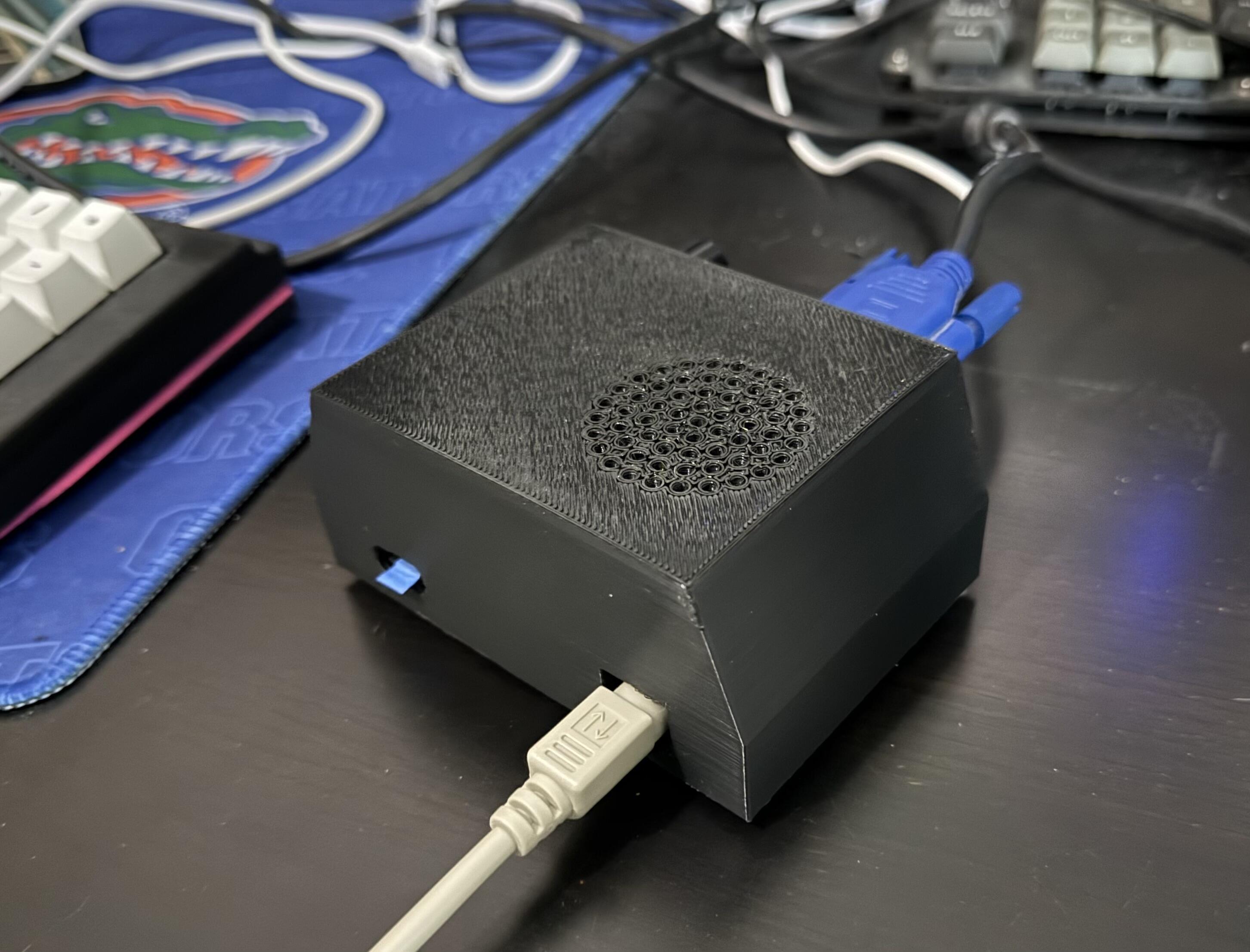
All done and usable. The case actually fit reasonably well, with two issues. First, I had a brain fart while designing and put the opening for the rp2040’s USB port on the wrong side of the centerline, so I had to nibble away 5mm on the other side. Second, the opening for the microSD doesn’t allow for how deep I soldered it onto the perfboard. I could actually remedy that by desoldering the reader and pushing it out to hang over the edge, but for now a pull tab of masking tape is working. What did work was setting the print to have 4mm thick solid “top” surfaces (file was printed upside down), and then simply drilling out screw holes; very forgiving of any imprecision in design, measurement, or printing, lol.
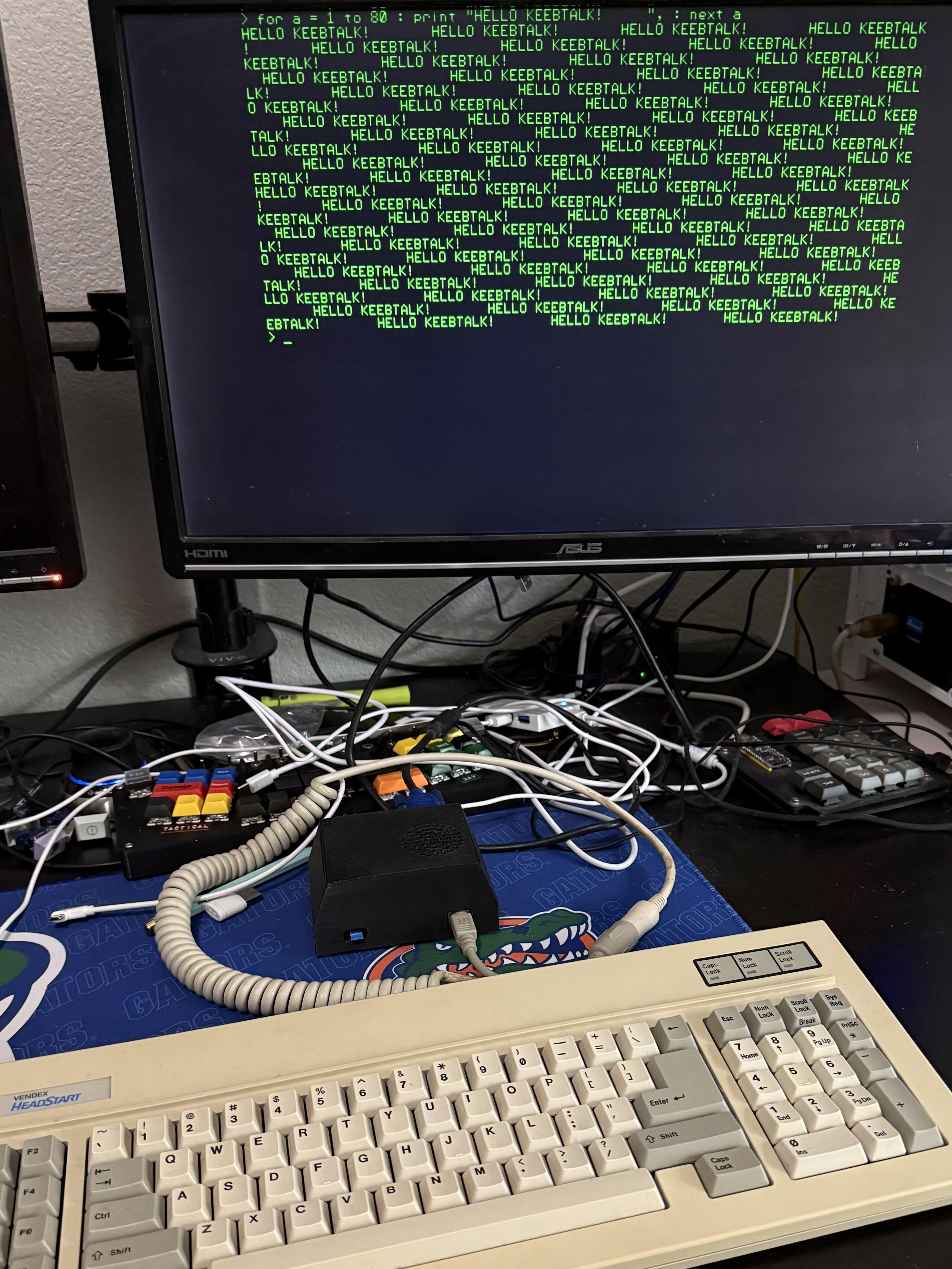
Speaking of the printer, my first layer was a bit crap, but I realized the filament had snapped beyond the sensor, so I was manually trying to feed it until the gears grabbed the intact length. This project was one I’ve had on my list for a while, but I finally got around to it, and the goal of a working, non-emulated BASIC computer has been satisfied. Don’t ask me why it’s important that it not be emulated; I don’t know.
Keyboard wise, the PS/2 circuitry is still fully operational, somehow, and I remembered that I had an AT board that could be passively converted. TBH the worn out Futabas are never going to compare to a decent buckling spring, though.
Sorry not sorry about the rat’s nest under the monitor.