What a beauty… and at that price it looks like a steal.
Thank you very much for this great build log!
1 Like
This e-yellow is my favourite type of yellow! Beautiful build as always!
1 Like
That’s super cool, thanks for sharing !
1 Like
Build #36: PC Norbaforce
The Norbaverse: Episode 3
Yes, episode 3. The Beach Norbatouch (build #16) and the Norbatouch Pi (build #19) were just early installments in the Norbaverse series, providing a little backstory for today’s episode. And once you’ve allowed yourself to rewrite history as you see fit, the door is wide open for build log possibilities. For example, this won’t even be the third @norbauer board I’ve built. There are others I have yet to incorporate into the Norbaverse (only Ryan’s order fulfillment database knows the full story - the rest of you will have to wait patiently). But with a soupçon of retcon, and a little warping of the space-time continuum, it’ll be no problem at all.
Back to our third installment. As always, I try to find waypoints in the journey that pass through new keyboard realms (for me, at least). When Ryan released the Ghost-of-Christmas-Future Edition polycarbonate Norbaforce Mark II, I saw a great opportunity for a quick tour through several parts of unexplored keebspace:
- Polycarbonate housings. Acrylic is the closest I’ve come so far, and I wanted to see how PC housings sounded and felt.
- The Realforce R2. I’ve had experience with Novatouch and Leopold boards, but not what is arguably the flagship of the current Topre lineup.
- The Norbaforce. I wasn’t in the hobby when this was initially released; Mark II was my first opportunity to work with this housing.
Ep 3 Act 1: Death of a Realforce
The donor board for this build is a Realforce R2 RGB TKL, for three reasons: it’s readily available, its MX-compatible sliders give us a much wider range of keycap choices, and its in-key RGB is tailor-made for use in a frosted polycarbonate housing.
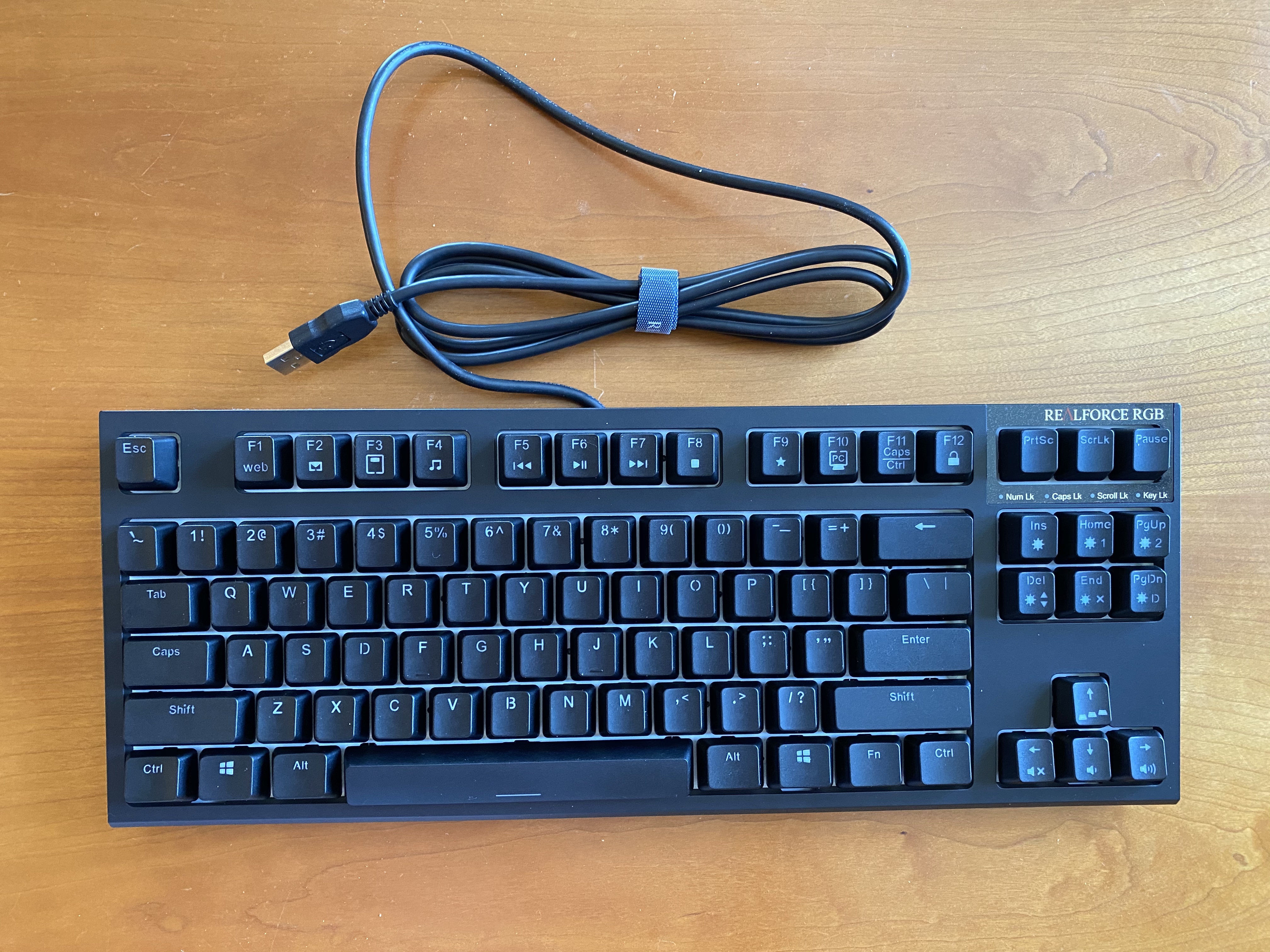
However, we’ll need to remove the original housing in order to transplant the PCB assembly into the Norbaforce housing. Before we start on that process, this is a good time to remove all of the stock keycaps. Have a look at all of those white MX sliders. Also, see that spring on the spacebar? If you plan to use it after modding, now is a great time to remove it and put it in a little Ziploc bag so you don’t lose it.
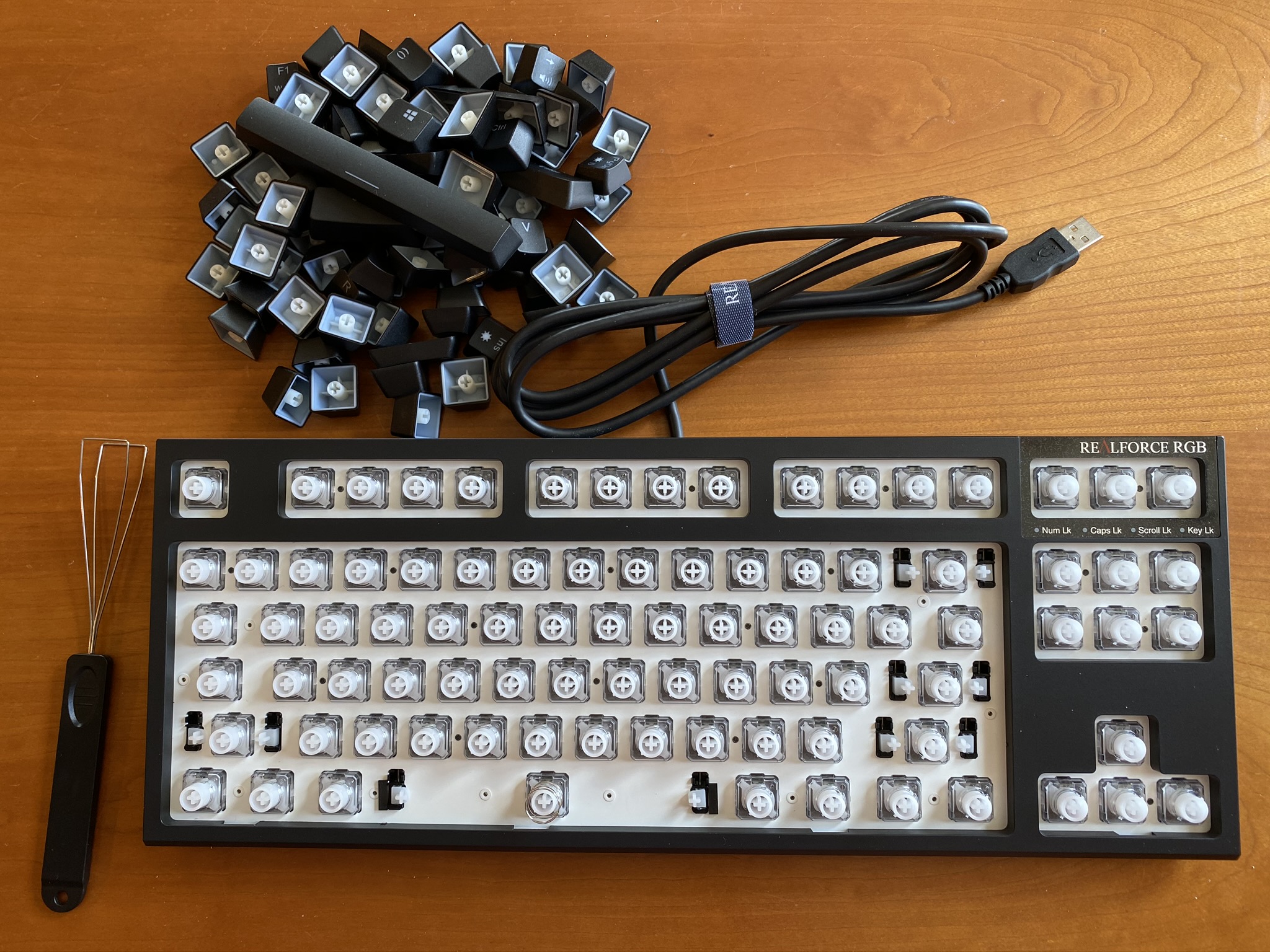
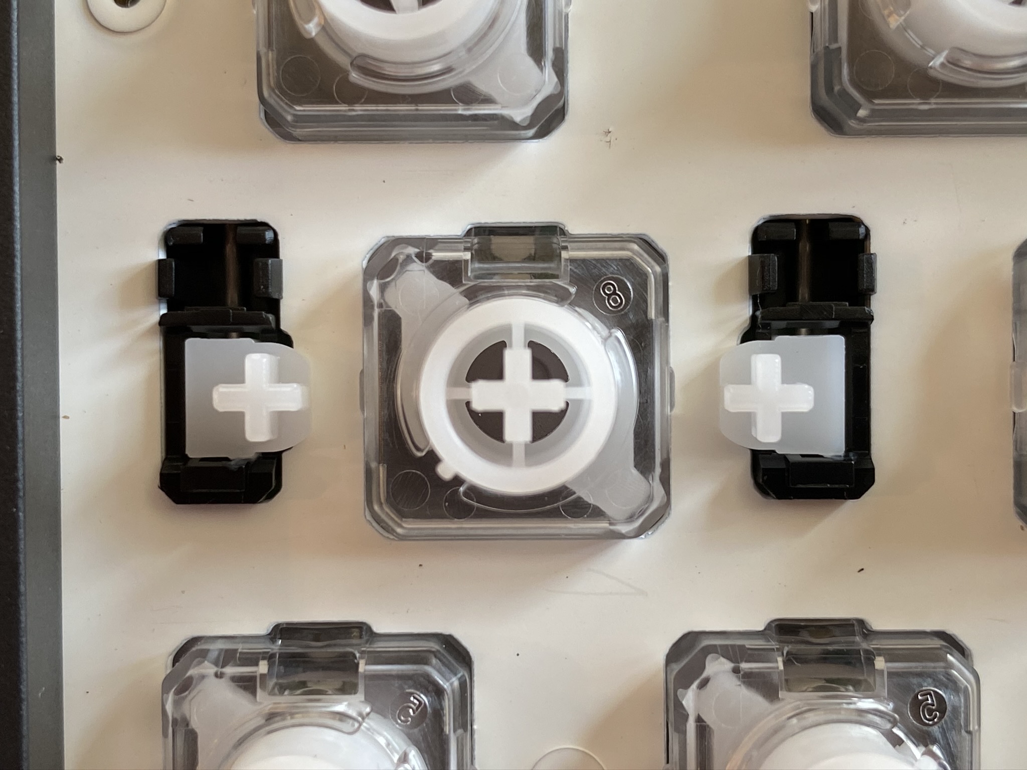
And while we’re here, take a look at the stabilizers in their natural state. The stabilizer housings appear to be clipped into the plate, and while the sliders look a bit different, they seem to function in the same way as a GMK clip-in stab, at least from this viewpoint.
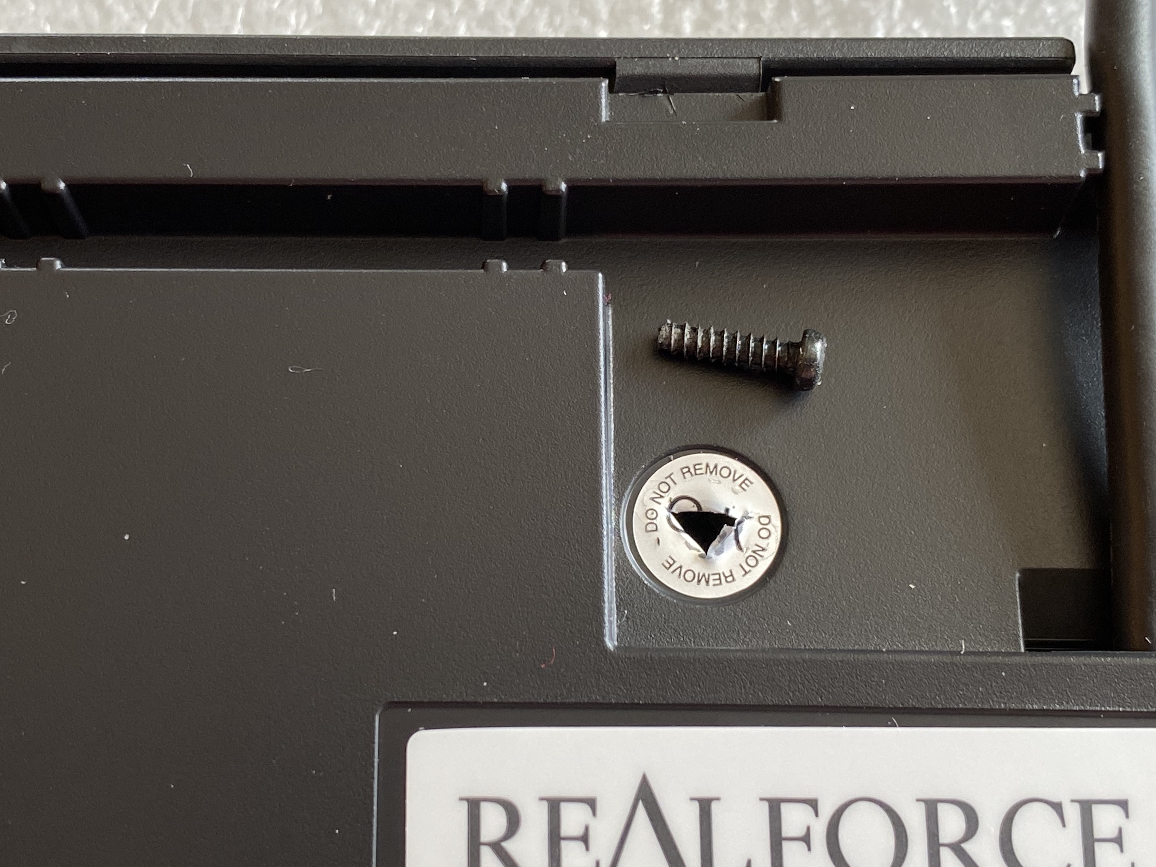
Flipping the board over, there are six tabs along the top edge which need to be pressed away from the body of the board to free the top edge of the base, and a screw that needs to be removed.
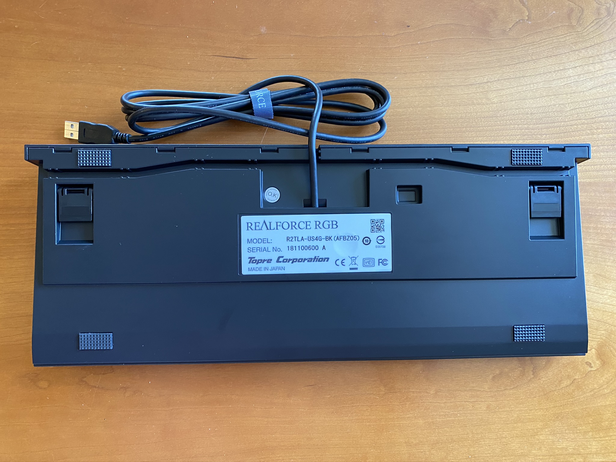
That screw lies underneath the little circular “O.K DO NOT REMOVE” sticker. Ready to void that warranty? You could carefully peel the sticker off, but I just went straight through with a Phillips screwdriver.
Before you start working on the bottom edge of the base, take a peek inside, and note that the Realforce USB cable is attached to the PCB by a connector. I might have been able to detach the connector at this stage, but I felt it would be easier to leave it attached and just exercise a bit more caution while removing the base, to avoid damaging the PCB.
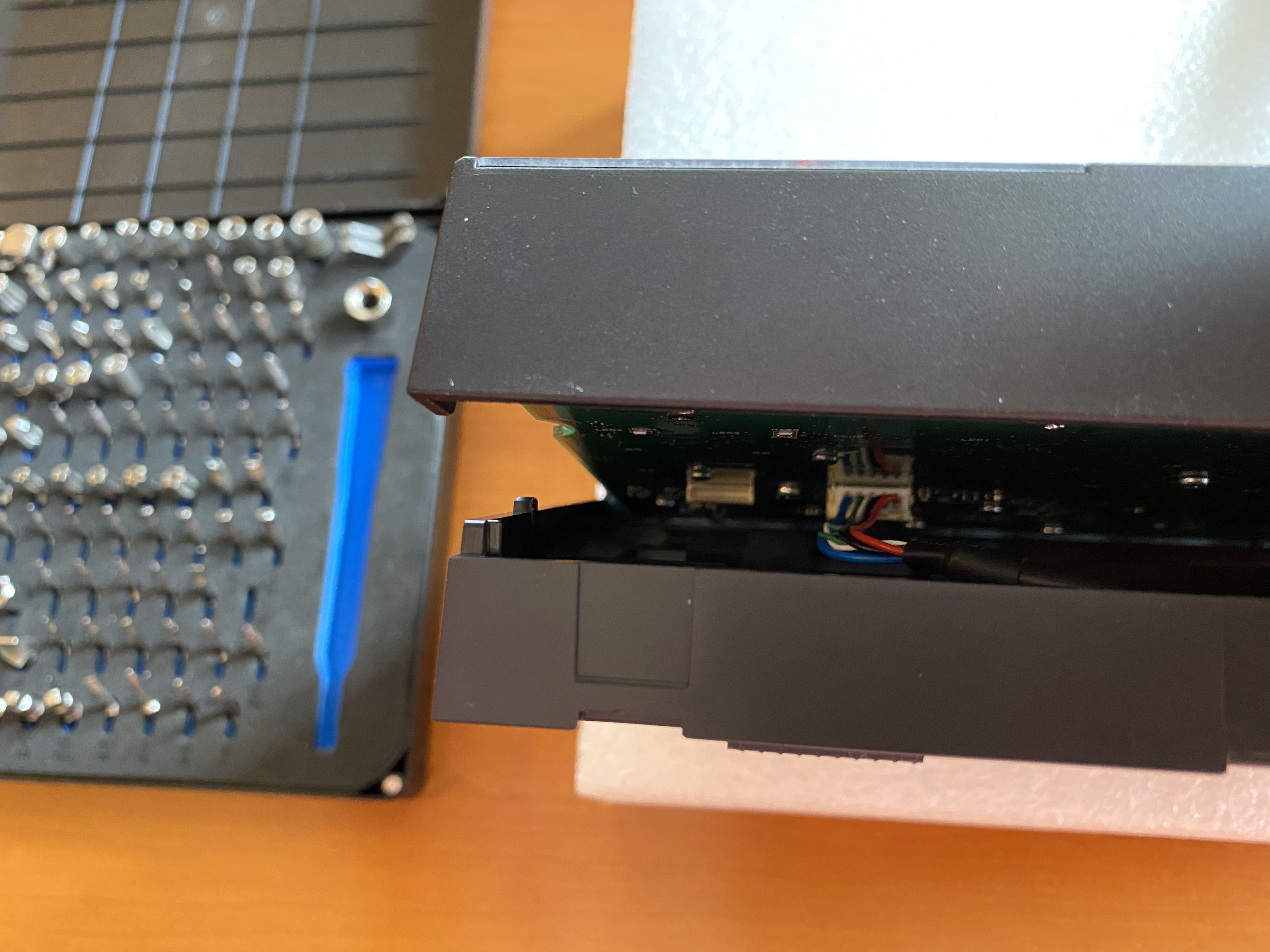
At this point, you need to separate the bottom housing from the top housing, along the bottom edge. The gap is narrow, but a credit card or small flathead screwdriver can be used to wedge them apart, and once you get one or two spots wedged apart, the rest will come apart a bit more easily. If you’re planning on reusing the stock housing, a credit card would be a better choice, as it’s likely to scuff up the case less than a flathead; I found it faster and easier to work with the flathead, and I wasn’t concerned about the original housing. Here you can see the two housing halves beginning to separate.
Now that we have the original housing removed, we can detach the PCB connector for the USB cable. Here’s a better look, right before we detach it.
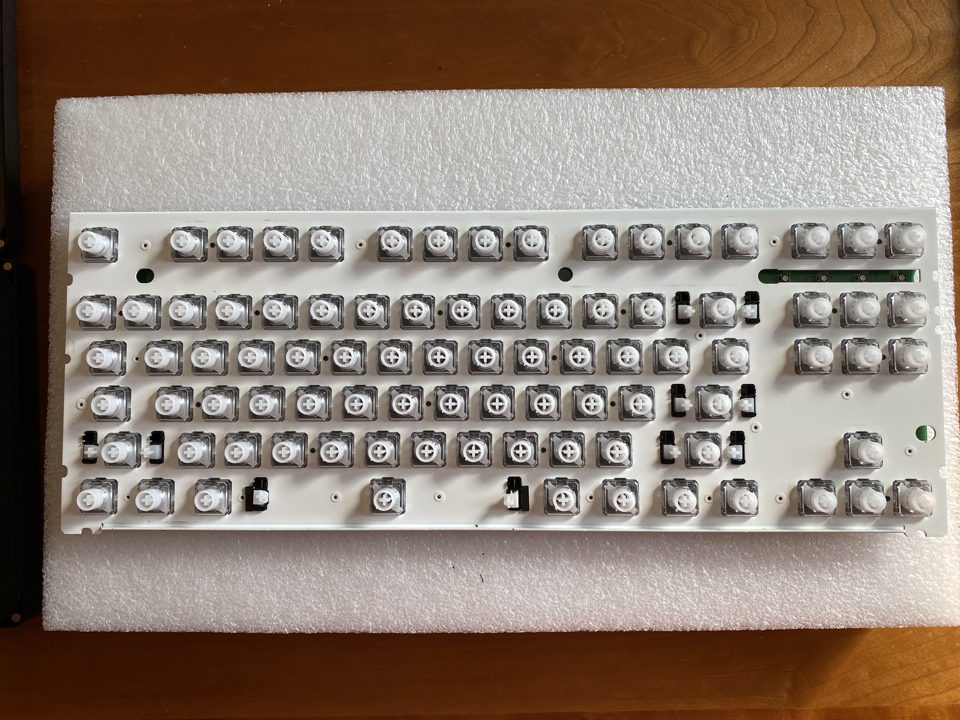
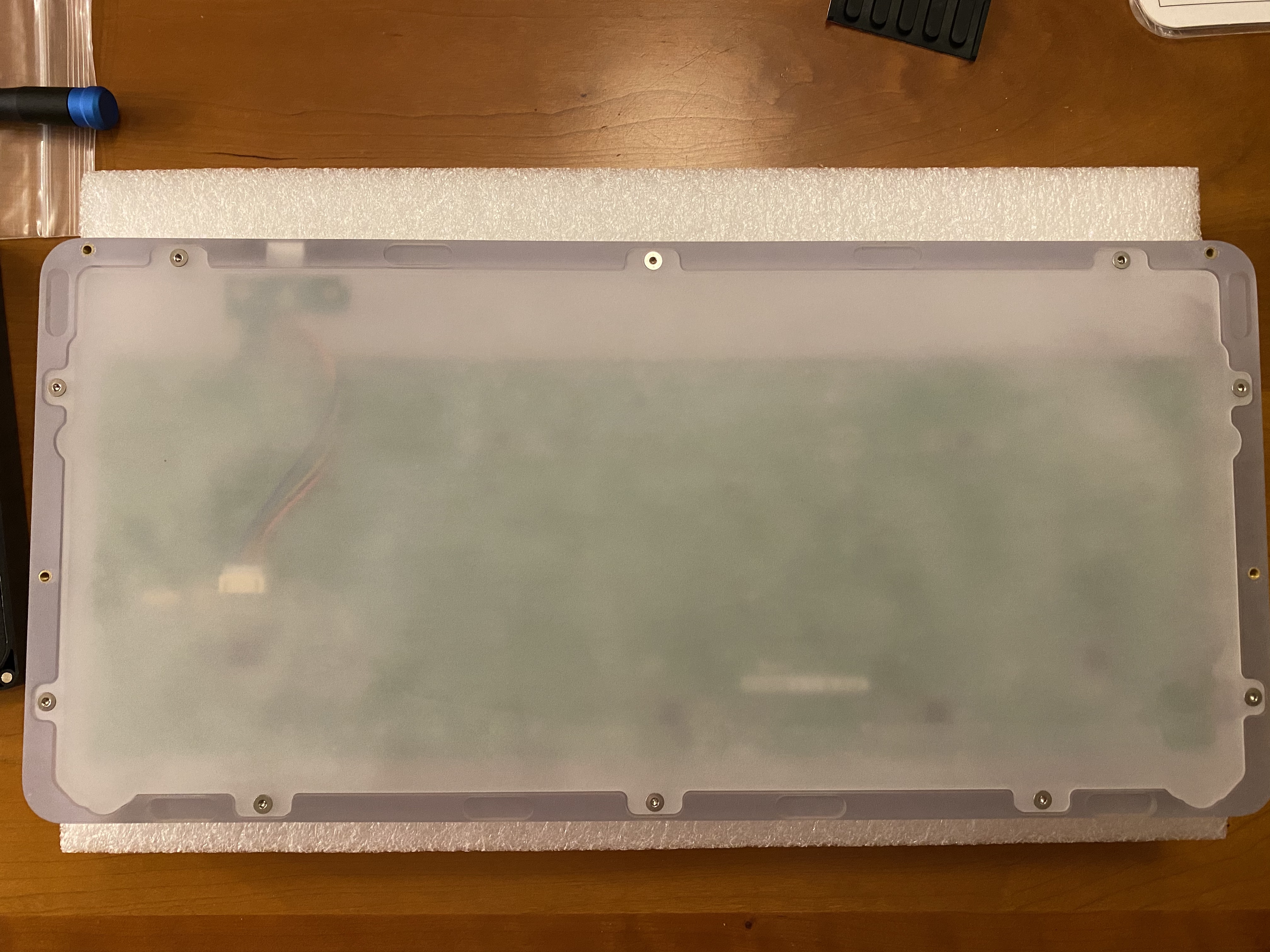
The PCB/plate assembly, free of the housing:
Ep 3 Act 2: Bag of Bones
If the only thing you want to do is a housing swap, then feel free to skip ahead to the final act. But, if you’ve tried the Realforce R2 RGB TKL out of the box, you will know that this board has some rattle, to put it mildly. Like dropping a bag of skeletons down a mineshaft. It’s not really usable in its native state, and so we’ll have to do some extra work to make it usable.
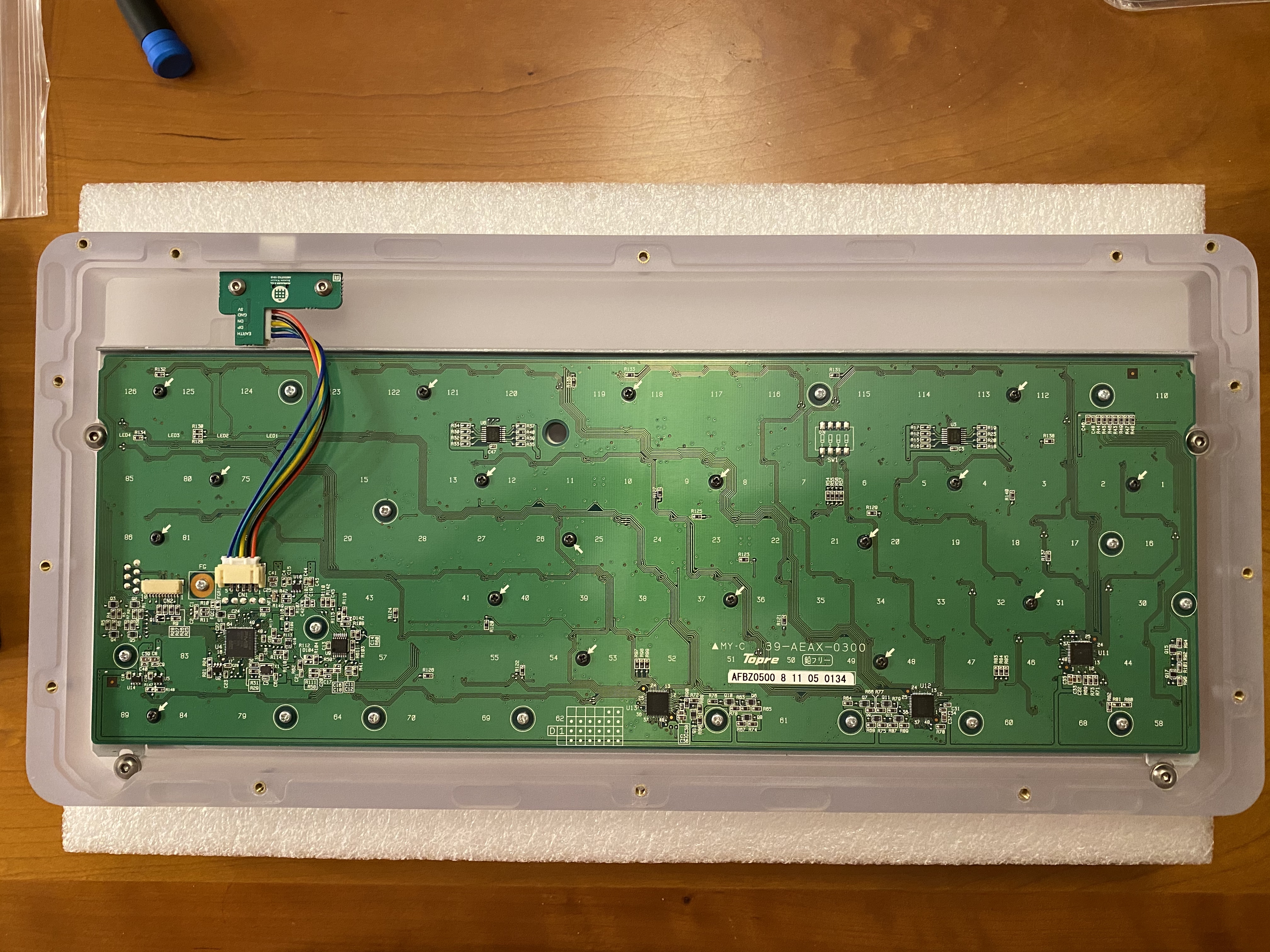
If you’ve ever modded a Topre board, you know that two things are in your future: lots of screws, and lots of lube.
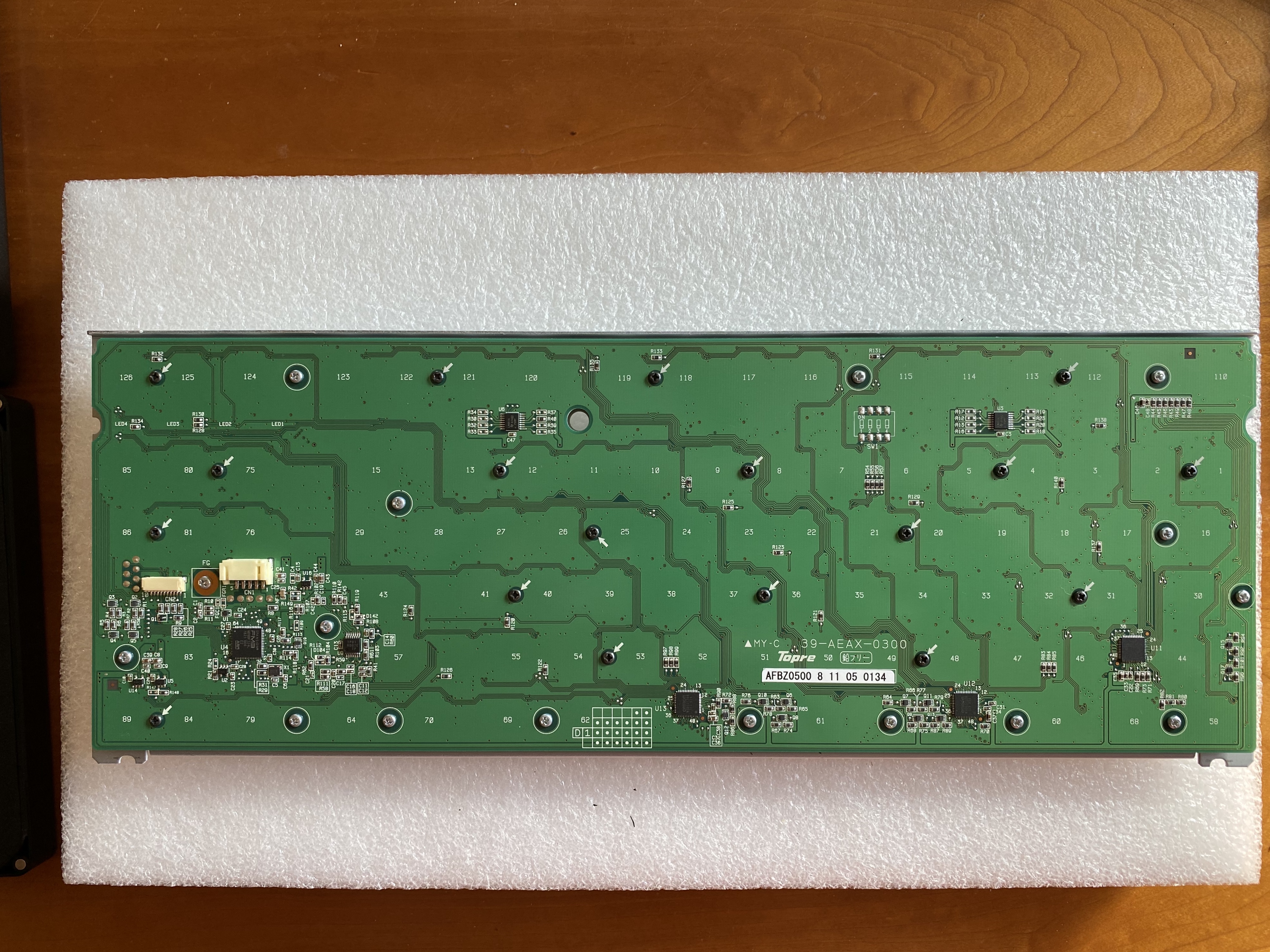
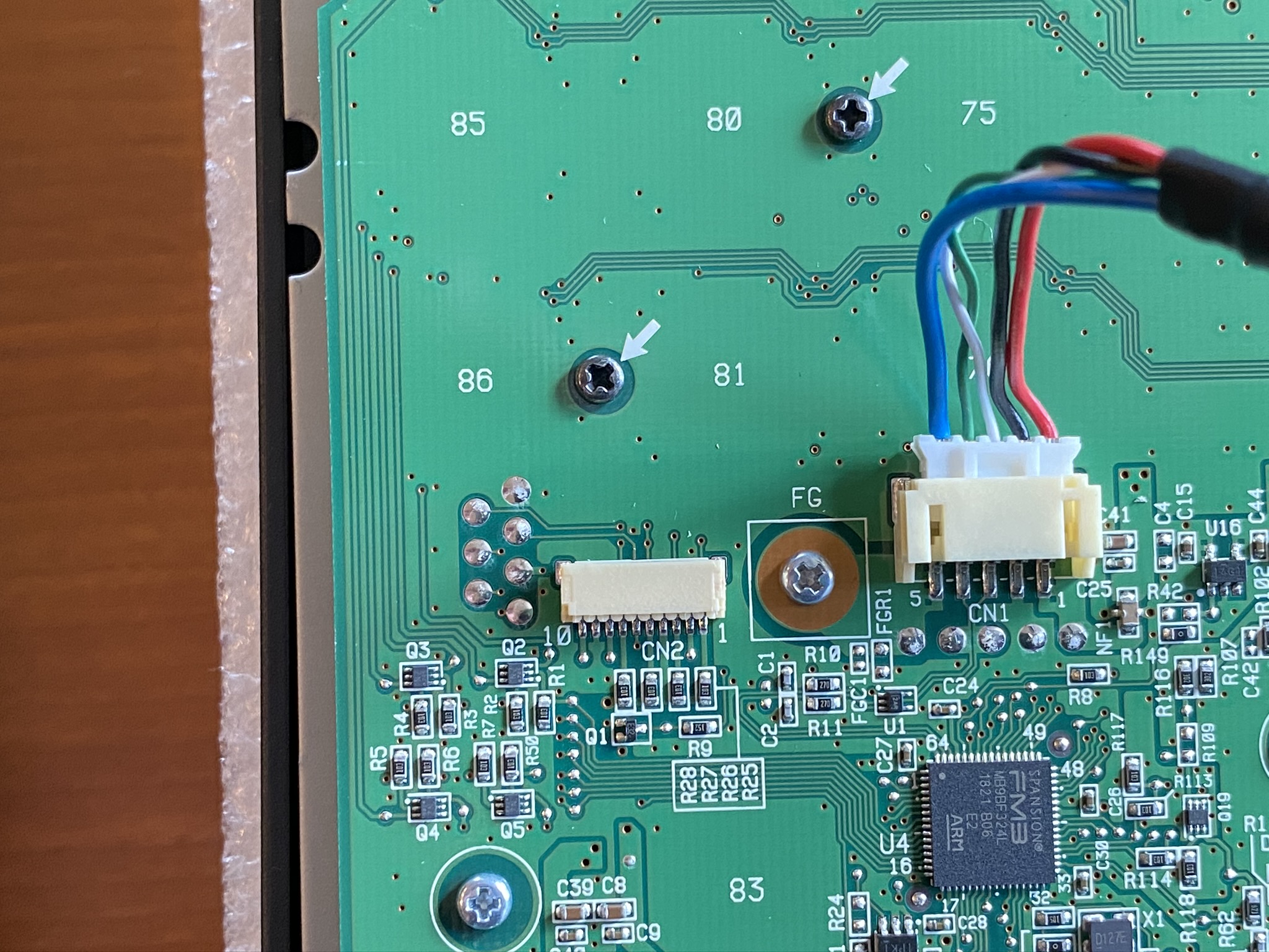
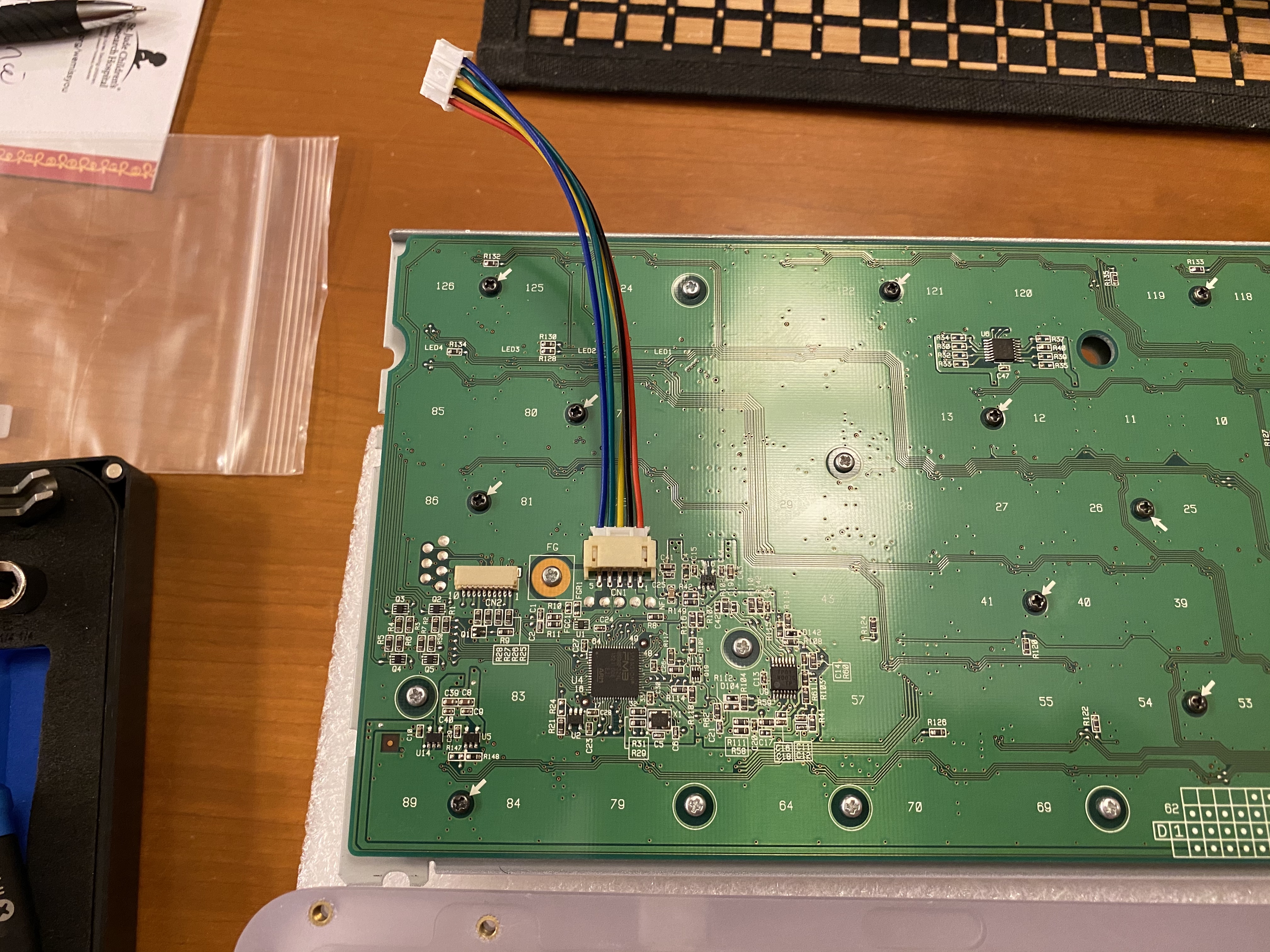
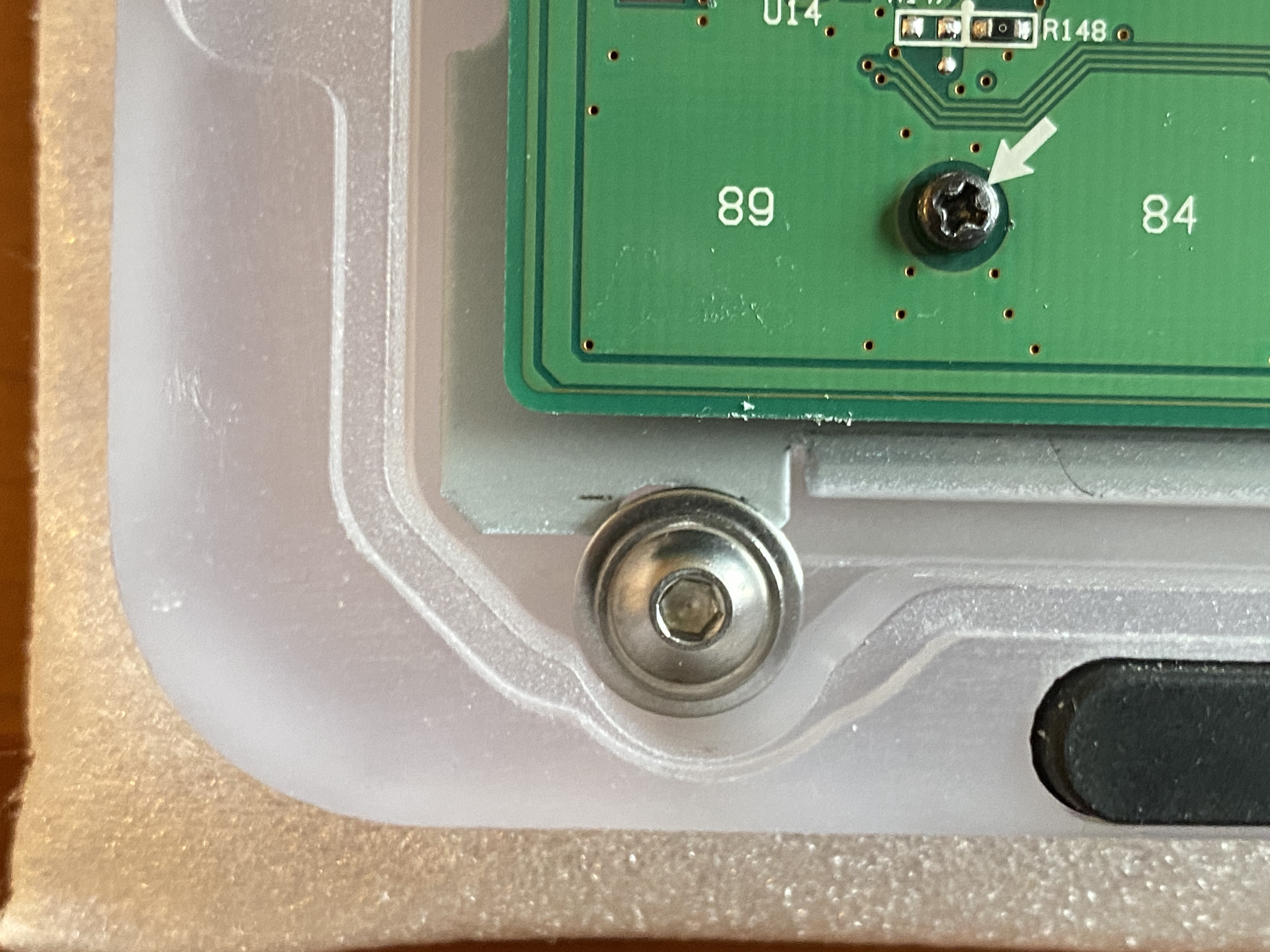
See all of those black screws, helpfully indicated by the white arrows on the PCB? See all of those silver screws, helpfully circled on the PCB? And that screw right next to the USB cable connector? All of these screws serve two purposes - to attach the plate to the PCB, and to apply even pressure for consistent electrocapacitive sensing on Topre PCBs. As a consequence, I offer two friendly notes of caution:
- Do not lose any of the screws as you remove them, or you may run into difficulty getting the board to function properly when you put it back together. A magnetic screw dish can be your best friend here.
- On the other side of the PCB, there are rubber domes, and underneath those, conical springs, all of which are held in place solely by pressure. When the screws are removed, that pressure is gone. If you’re not planning on swapping in different rubber domes (and for this build, we’re not), then it’s worth trying your best not to disturb the existing domes, as realigning them is time-consuming, and the conical springs underneath are insanely light and want to fly everywhere if given a chance.
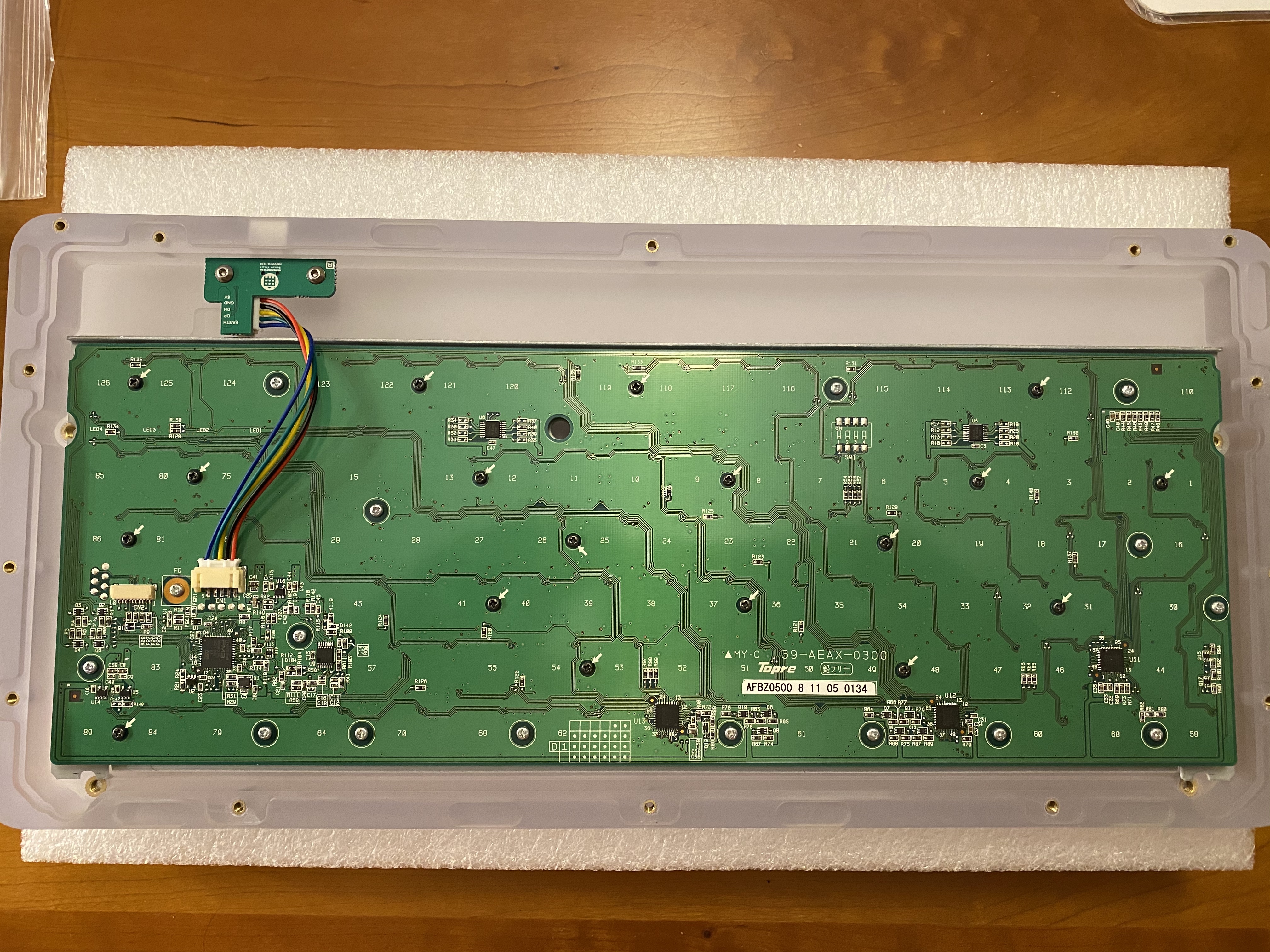
With those cautionary notes sounded, we are in the middle act of a three-act episode, so let’s go ahead and live dangerously. Drama! First, holding the PCB and plate together tightly (remember, no screws holding it together anymore!), we invert the assembly, and set it down gently.
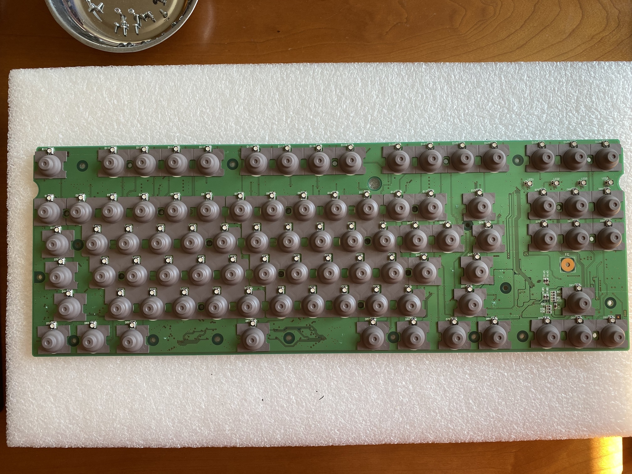
Next, I’ve found that if you are exceedingly careful when lifting away the plate, there is often enough residual stickiness between the PCB and the rubber sheet to keep that sheet in place, exactly where you want it to be. And that turned out to be the case here - lifting the plate away cleanly, we see an undisturbed field of domes. We set this aside gently, out of the way of our working area, and out of the way of pets, kids, or any other instruments of destruction you keep around the house.
We can now take our first look at the underside of the plate assembly. Note that each slider has a little notch around its perimeter. At first I worried that there might be a specific orientation for each slider mounted into its housing, but it seems they’re just oriented one way or the other at random in each housing.
Removing the sliders is straightforward - just apply pressure from the top, and they’ll snap out. I found it easiest to do this with a fat hex bit on a screwdriver, just punching the sliders out; you can get all of them out in a couple of minutes.
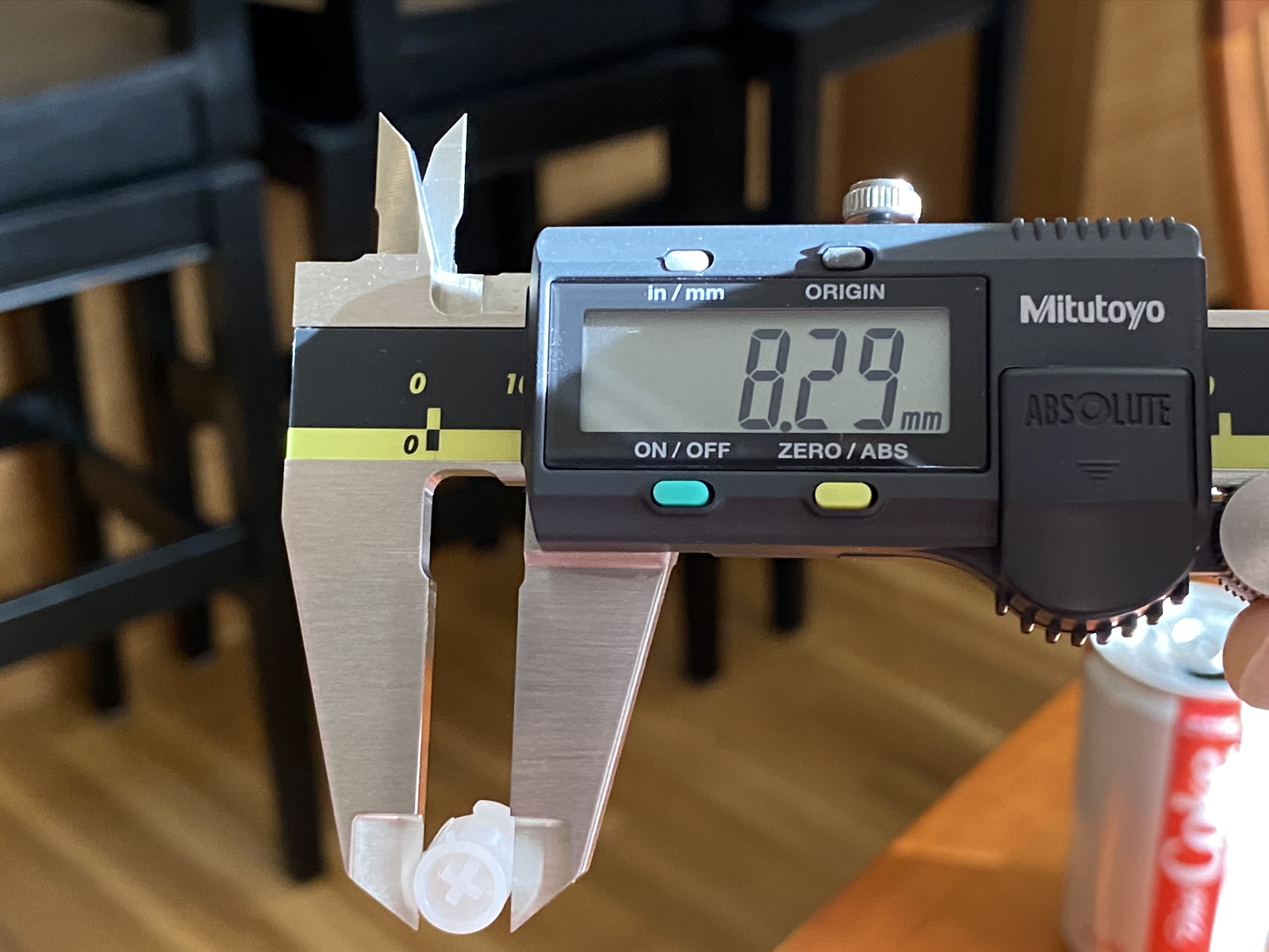
In a previous Norbaverse episode, we discussed variations in MX slider widths. For completeness, here’s the result for these new MX sliders - a bit narrower than the Novatouch sliders, but not as far off as the KBDfans sliders.
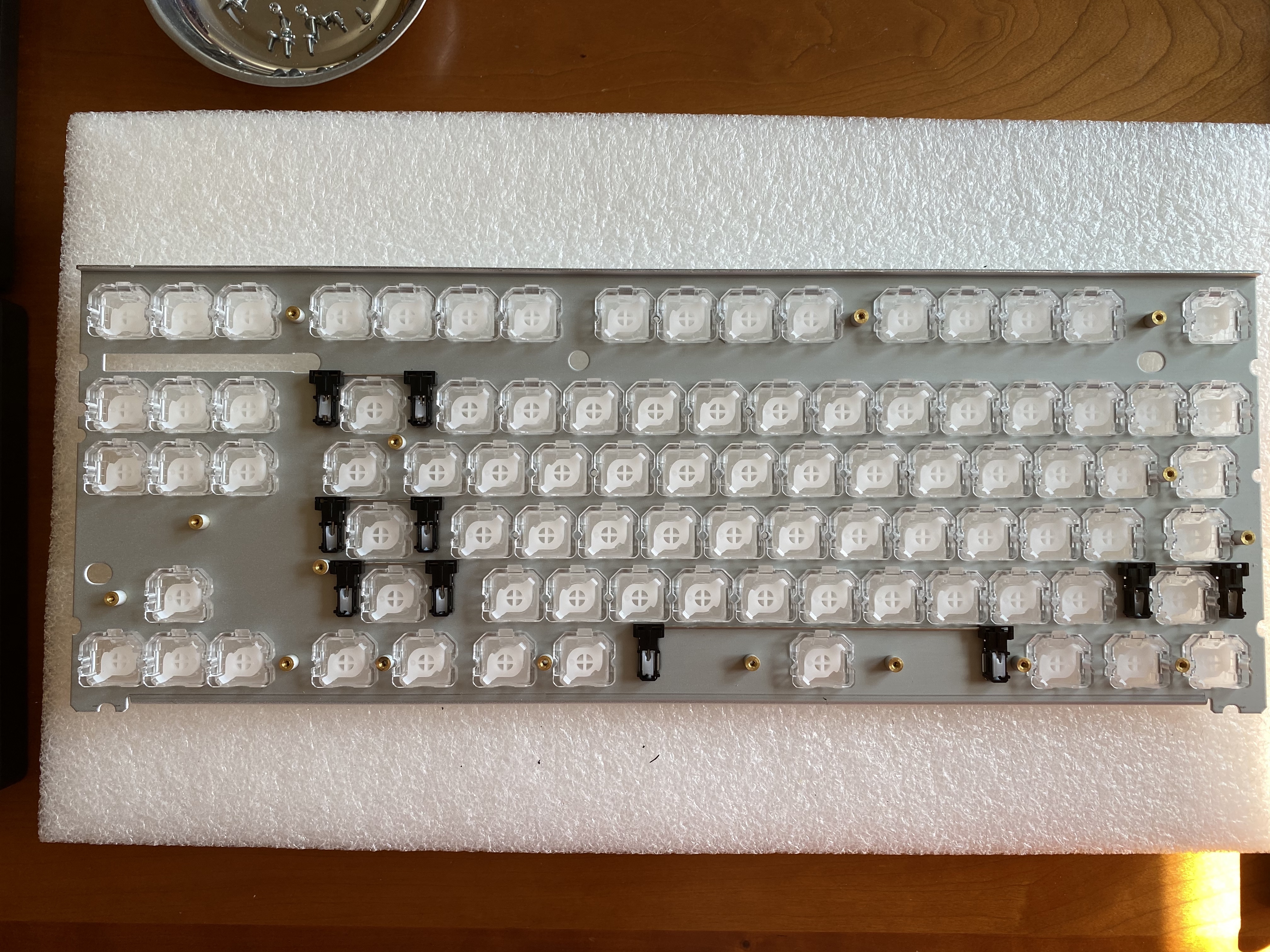
Once you’ve reached this point in the build, you’ll notice that the housings have an exceptional degree of rattle in the plate, and looking more closely at the perimeter of each housing, the tolerances aren’t exactly tight. To some extent this isn’t actually an issue; once the slider housings are under pressure again from the rubber domes beneath them, housing movement is significantly if not completely inhibited.
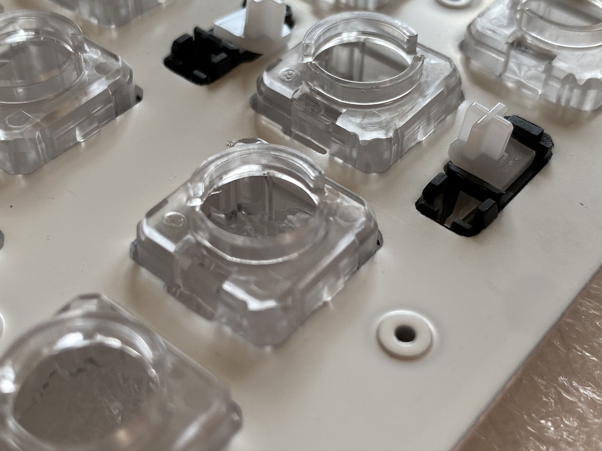
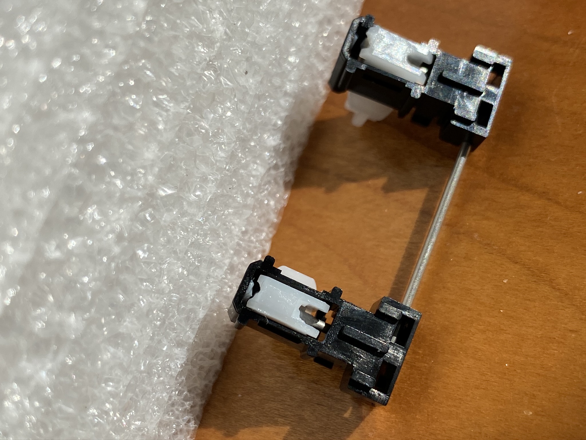
From that angle, we also have a good look at the clips for the stabilizer housings; you can easily pop them out by simply applying pressure with your fingers to the two black tabs on the front of the housing, pinching them inward while pressing down.
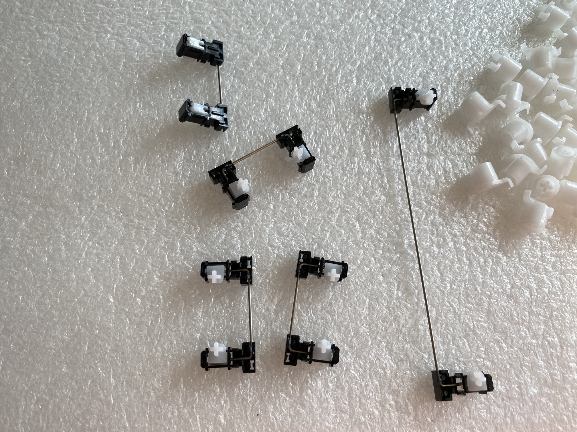
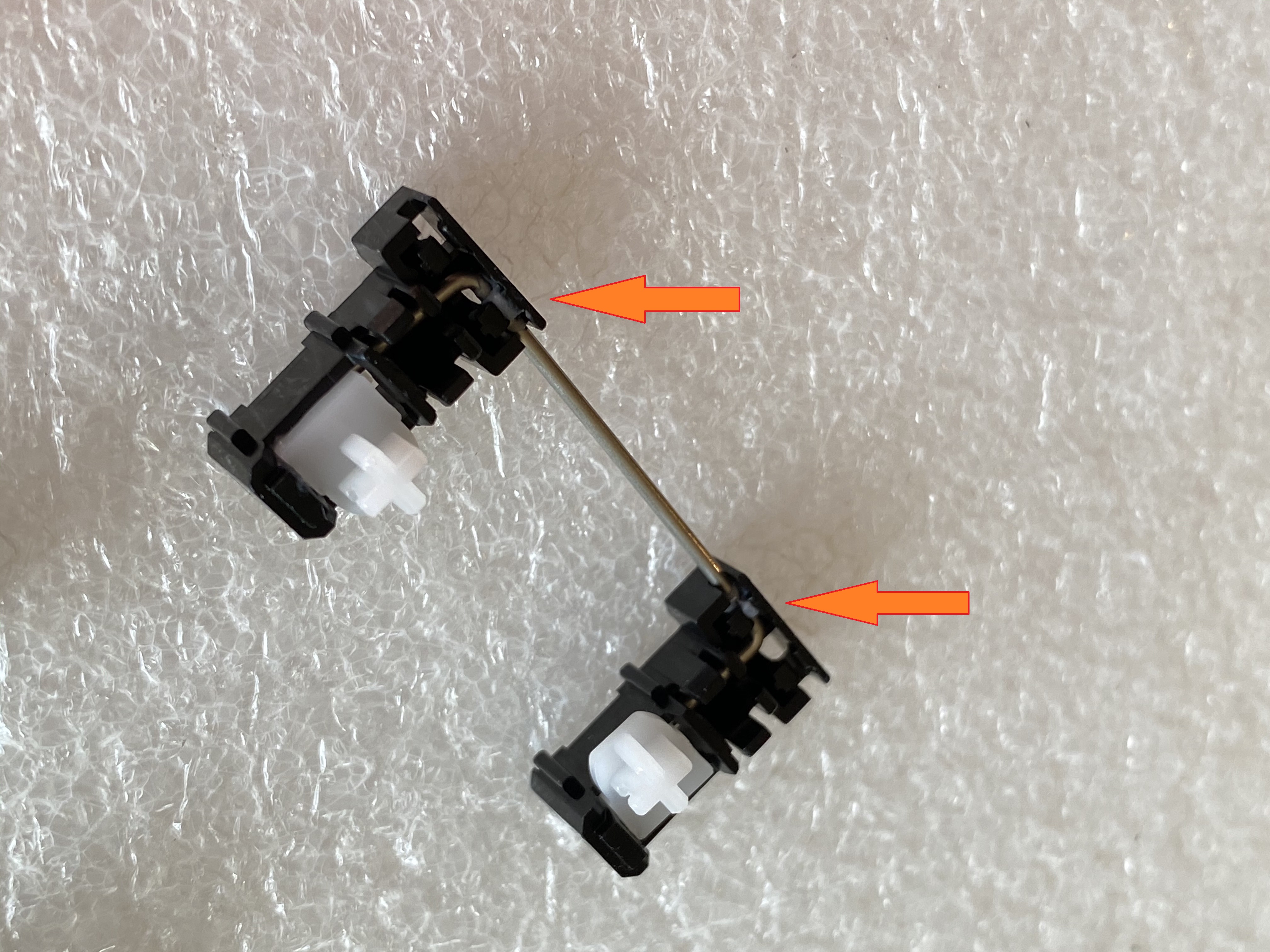
If these were GMK stabs, at this point I’d pop the wires out, remove the stab sliders, and lube in the usual way. But, these stabs are different. Right where you would expect a gap for the wire to pop out, these housings instead have what looks like a bit of molten plastic squirted into the gaps to hold the wire in place.
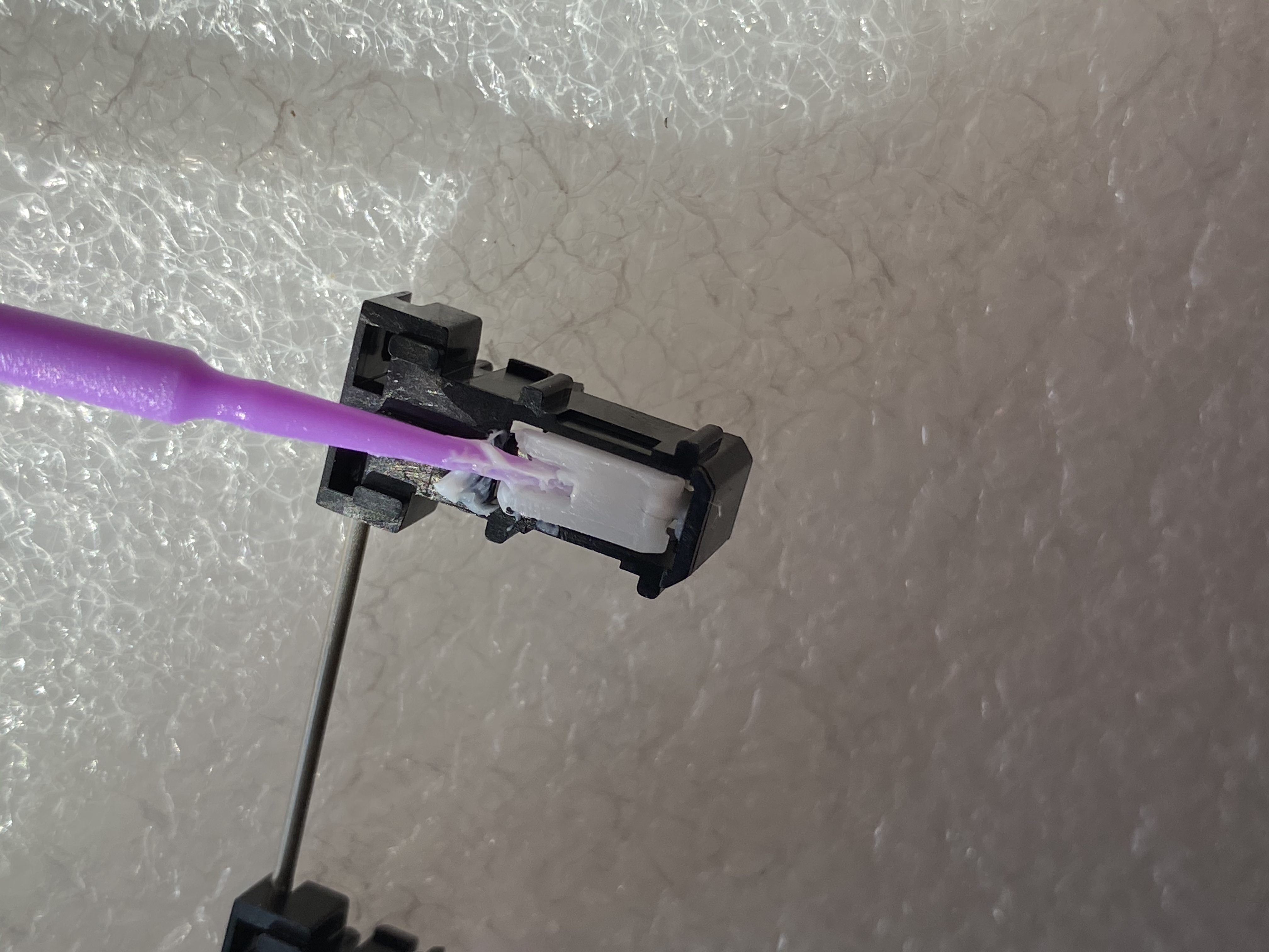
I considered just cutting through those bits, but I worried that the wire might just become too loose to be usable. So, instead, we’ll just leave the assembly in place, and apply as much lube as we can. We’ll start with the underside, in the gap where the wire inserts into the slider.
I’ve been finding that Christo-Lube works well on stabs, and is quite safe to apply in quantity on GMK stabs without worrying about introducing sluggish stab behavior, so I chose to use Christo 129 on these stabs. To get into that small gap in the slider, a dental applicator works reasonably well.
After that, it’s just a matter of filling the same spots from the top, and applying as much as you can where the wire meets the housing.
For the key sliders, the only spots that require lube are on the housings, where the sliders make contact with the housing. For this application, 3204 works well, and you can be a bit more liberal in your application than you would be with an MX-style switch, without adverse impact.
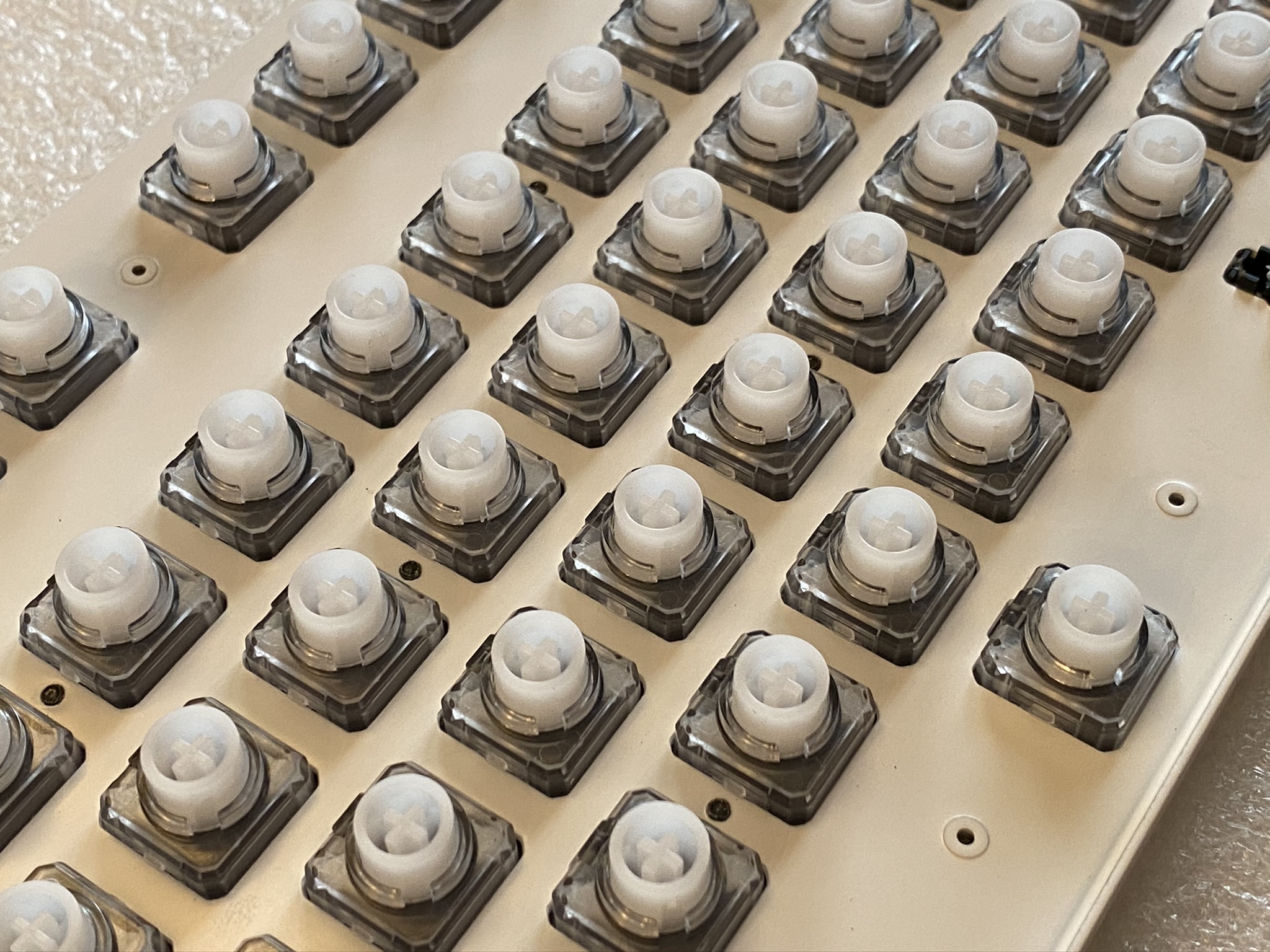
Finally, once you’ve lubed all those housing rails, you’ll want to apply silencing rings. In an unaired episode of the Norbaverse, I tried Deskeys #2 rings, but found them to provide insufficient silencing, so I went with the #3 rings for this build. Here we see all of the sliders with silencing rings applied, and snapped back into place.
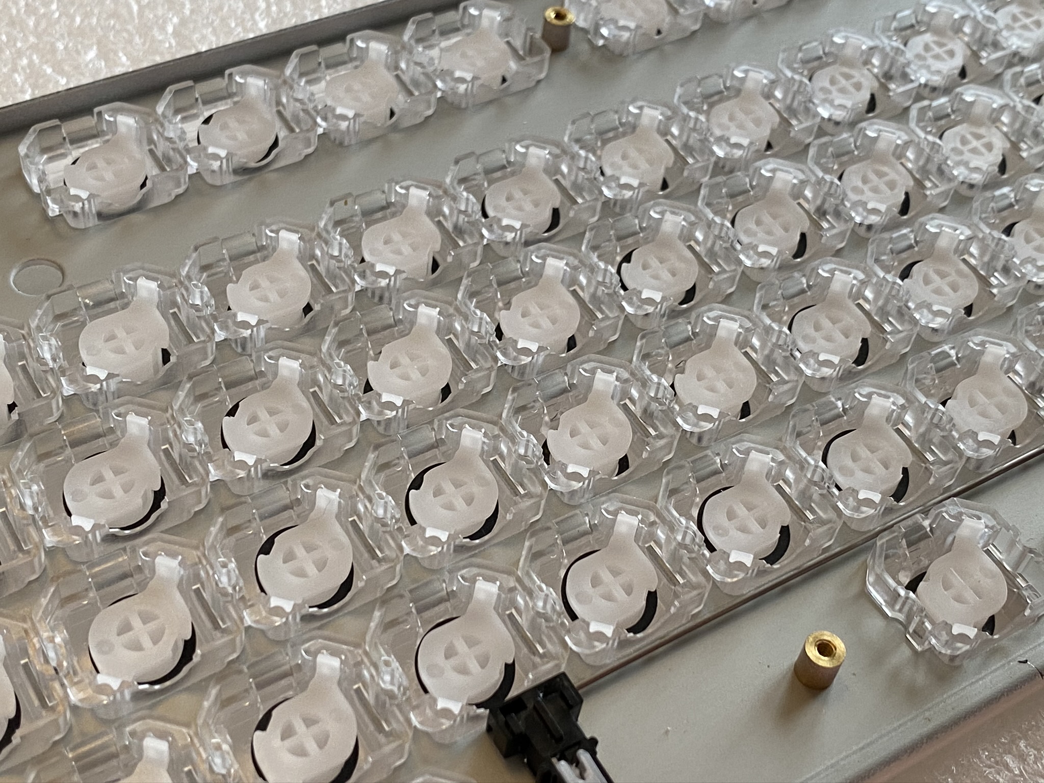
And, the view from the top. I’ve since become aware that Deskeys offers “RGB” versions of the rings with cutouts for the LEDs to shine through more cleanly, but as we’ll see later, not a big deal for this build.
From here, it’s just a matter of (gently) aligning and placing the plate back on top of the rubber domes and PCB, (gently) holding the plate and PCB together while inverting the entire assembly, and then getting all of those screws back in. At this point, it’s a very good idea to test that the PCB works, by reattaching the original Realforce USB cable and firing up a switch tester, before going further. In this case, all good on the first try. Happiness!
Ep 3 Act 3: Birth of a Norbaforce
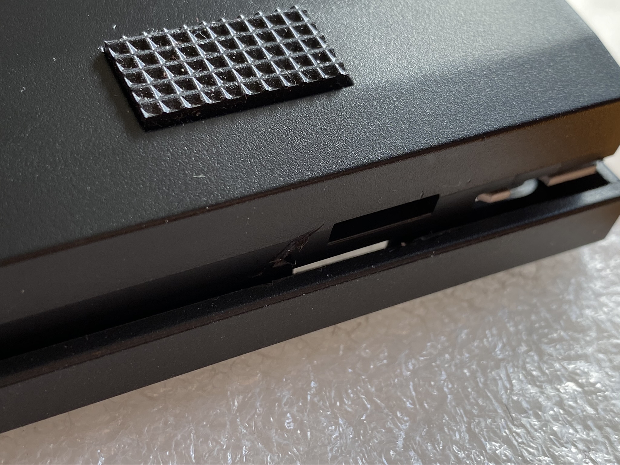
As usual, Norbauer’s packaging is premium - the Norbaforce housing comes in lovely well-padded packaging, additional parts come in a stylized branded sleeve, and the abrasive pads come in… wait a minute. Abrasive pads?
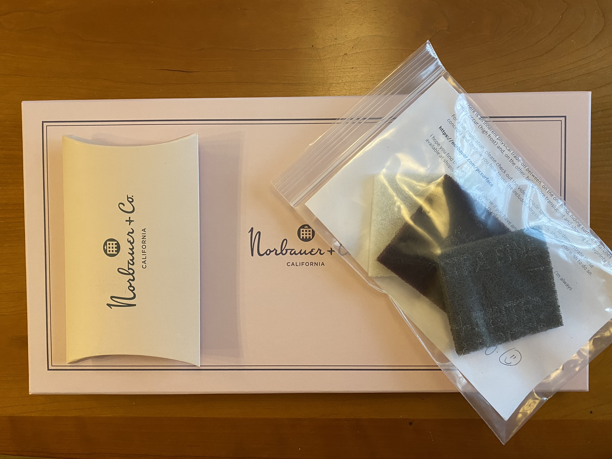
At this point, dive into a wormhole in the Norbaverse, and please allow Ryan to school you on the upkeep of frosted polycarbonate. I’ll wait for you to emerge on the other side.
The Norbaforce Mark II uses a USB connector daughterboard, and a special cable to connect that daughterboard to the Realforce PCB. Our first step is to attach that cable to the PCB:
The daughterboard itself is a modest affair, which attaches to the Norbaforce housing with the included screws.
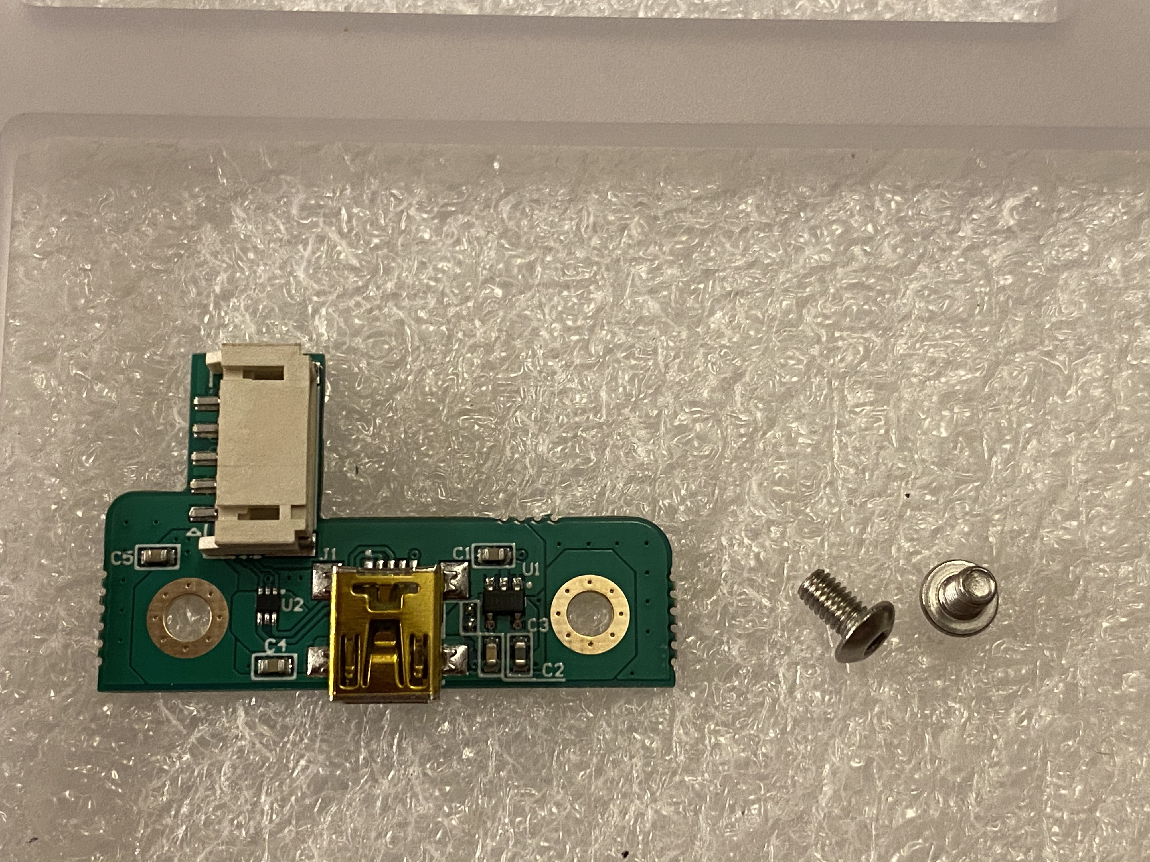
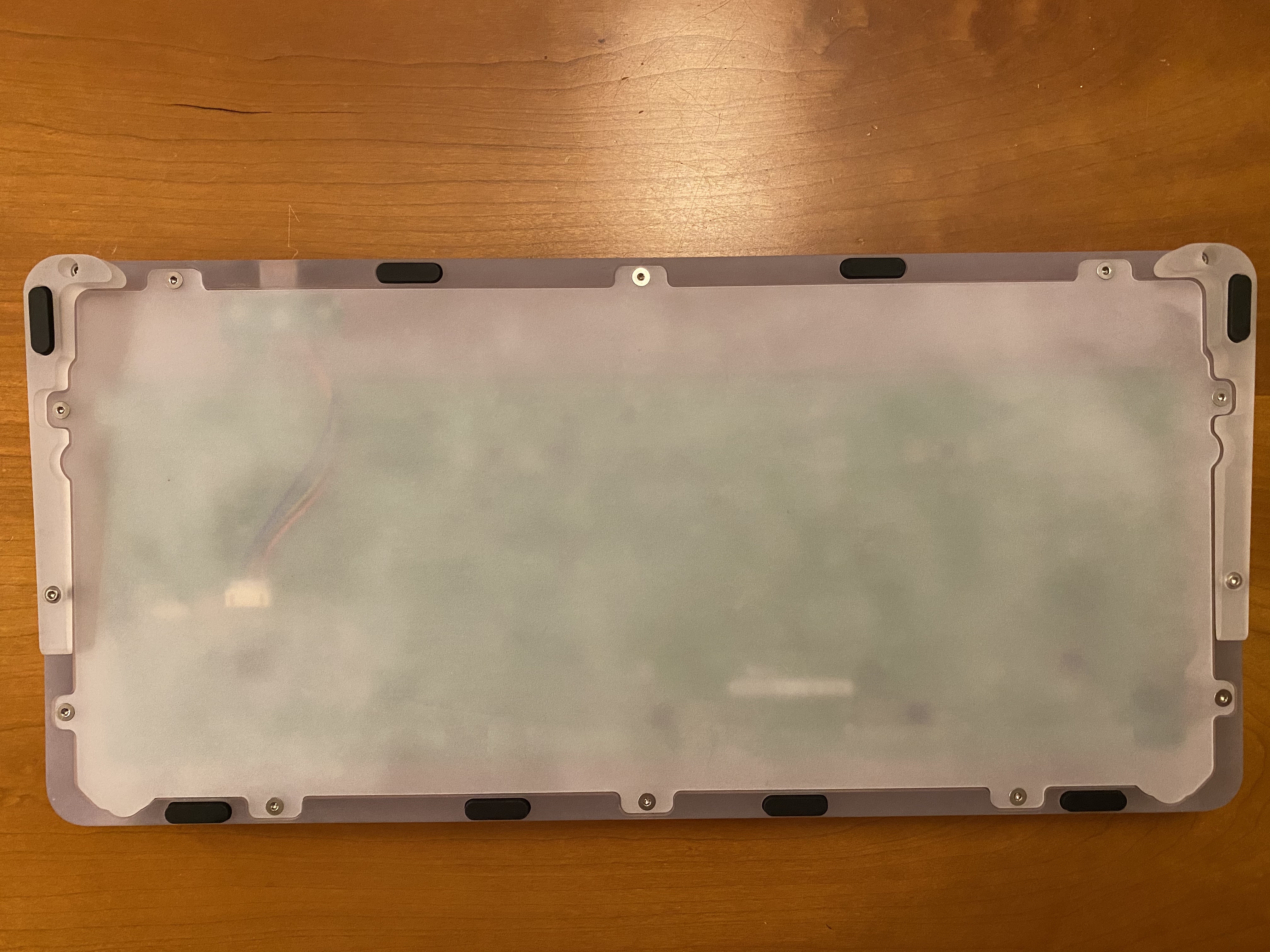
I found it easiest to first attach the other end of the cable to the daughterboard, and then screw the daughterboard into the Norbaforce base. We also get our first look at the PC housing, with a consistent frosted finish throughout.
The PCB is then held in place by four more screws, although I found that the top two screws are doing the majority of the work, and getting those two aligned properly will lead to proper alignment of the PCB with the housing. The bottom two screws make minimal contact.
(One month after I wrote this build log, a comment from Ryan on the GB thread made me realize why there’s minimal contact - I didn’t use the included washers for the bottom two screws. Argh! After a quick bit of screwdriver work, here’s what a bottom mounting point should look like with the washer.)
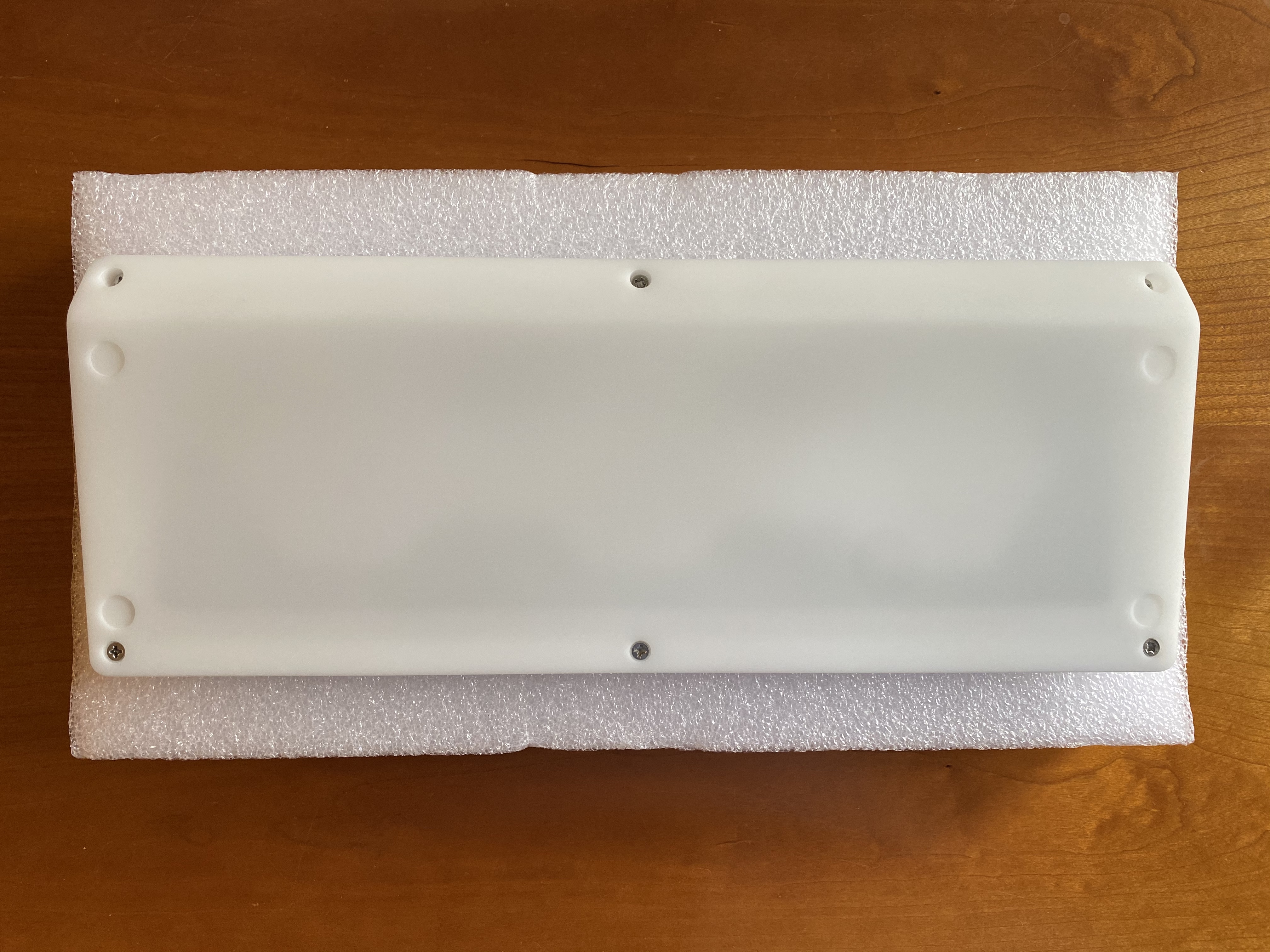
A comparatively thin piece of polycarbonate, with a more variable level of finish, screws to the back of the housing to close the underside of the case. The tolerance with respect to the PCB’s USB connector is quite tight; if you choose to put shelf liner or foam in the case, you would need to make a cutout for this connector for the liner to fit cleanly in the case.
I like some tilt to my boards, so we’ll install the included risers for the Norbaforce. Pre-installation:
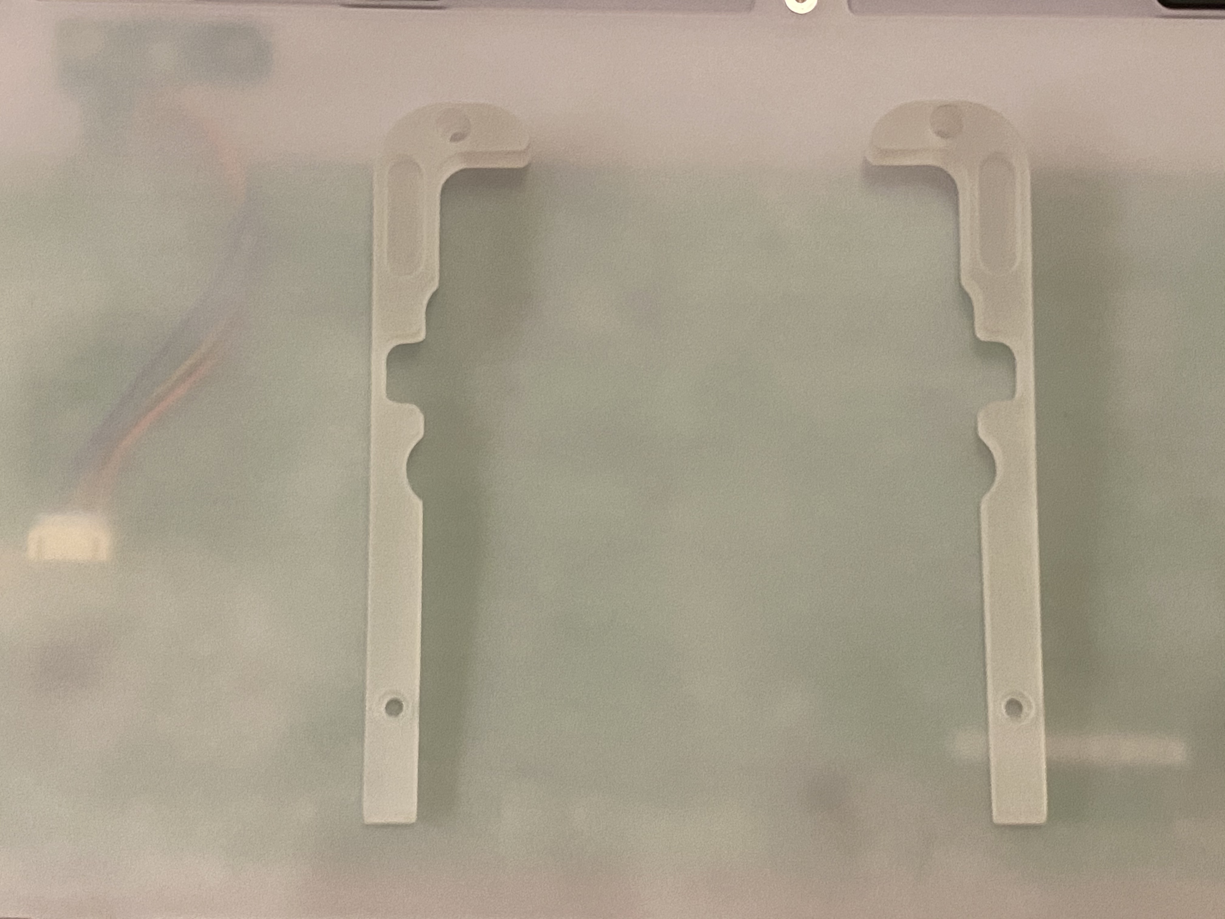
The risers simply screw into place on either side of the case. Note that if you plan to use the included bumpons on the Norbaforce, you need to first decide whether you are going to use risers. I had applied bumpons before I put the risers on, when I discovered that the risers won’t actually install with a bumpon underneath them - so I had to peel those two bumpons out of their cutouts on the bottom housings, install the risers, and then place them again, this time on the cutouts on the risers. Sigh. That’s also why you see the two bumpons at the top of the case, which will make contact with absolutely nothing when the risers are installed. Don’t be like me - inspect the components first!
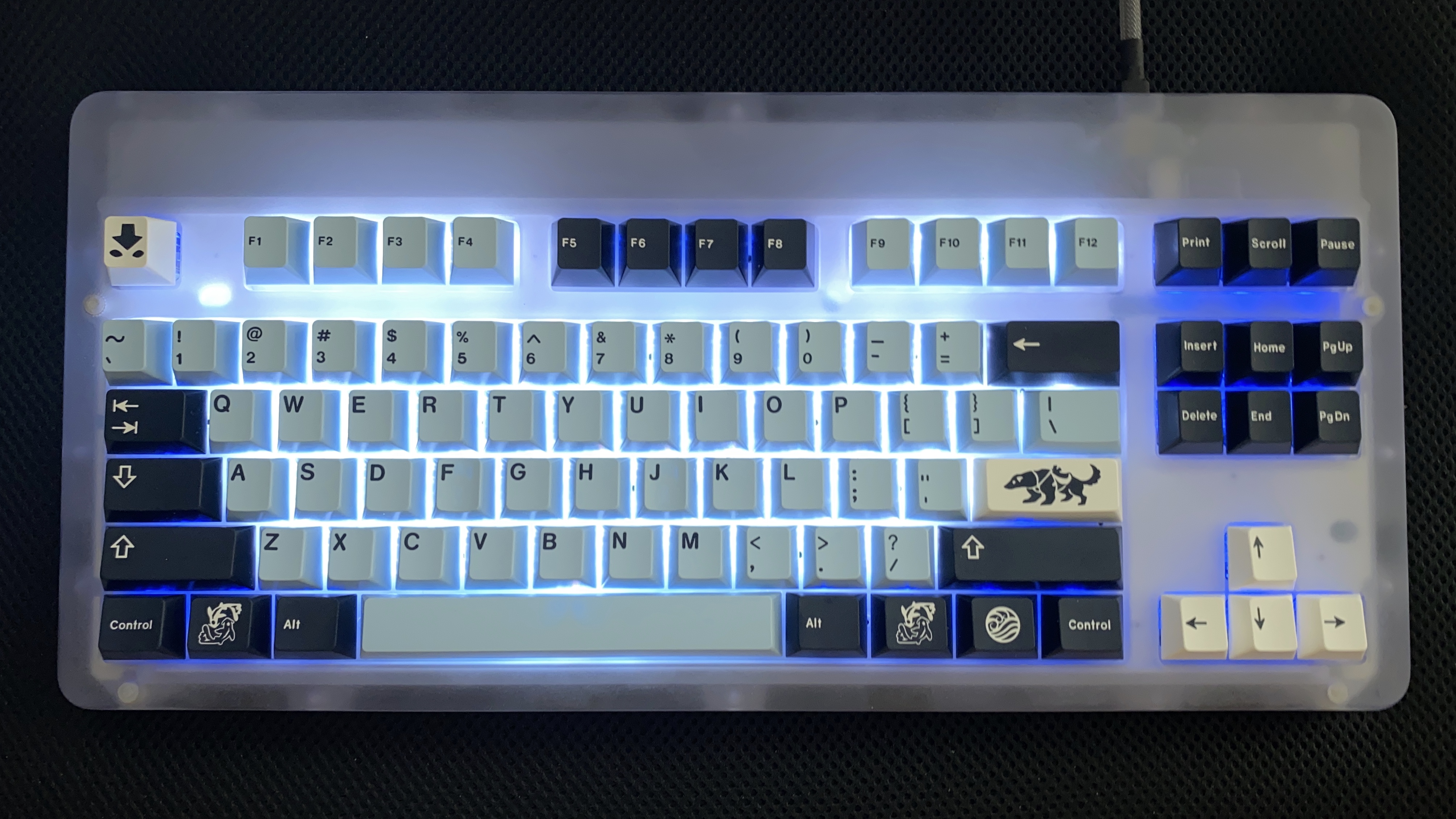
Getting close now - here’s our first look at the top of the PC Norbaforce.

Remember that spacebar spring, that I told you to put into a Ziploc bag? Now’s the time to put it back in place.
Or not. Even after all the lube, I still had some spacebar rattle. Part of that was addressed by shoving even more 129 into the stab housings, but the other part was addressed by removing this spacebar spring. YMMV, but it seems to do essentially nothing as far as I’m concerned.
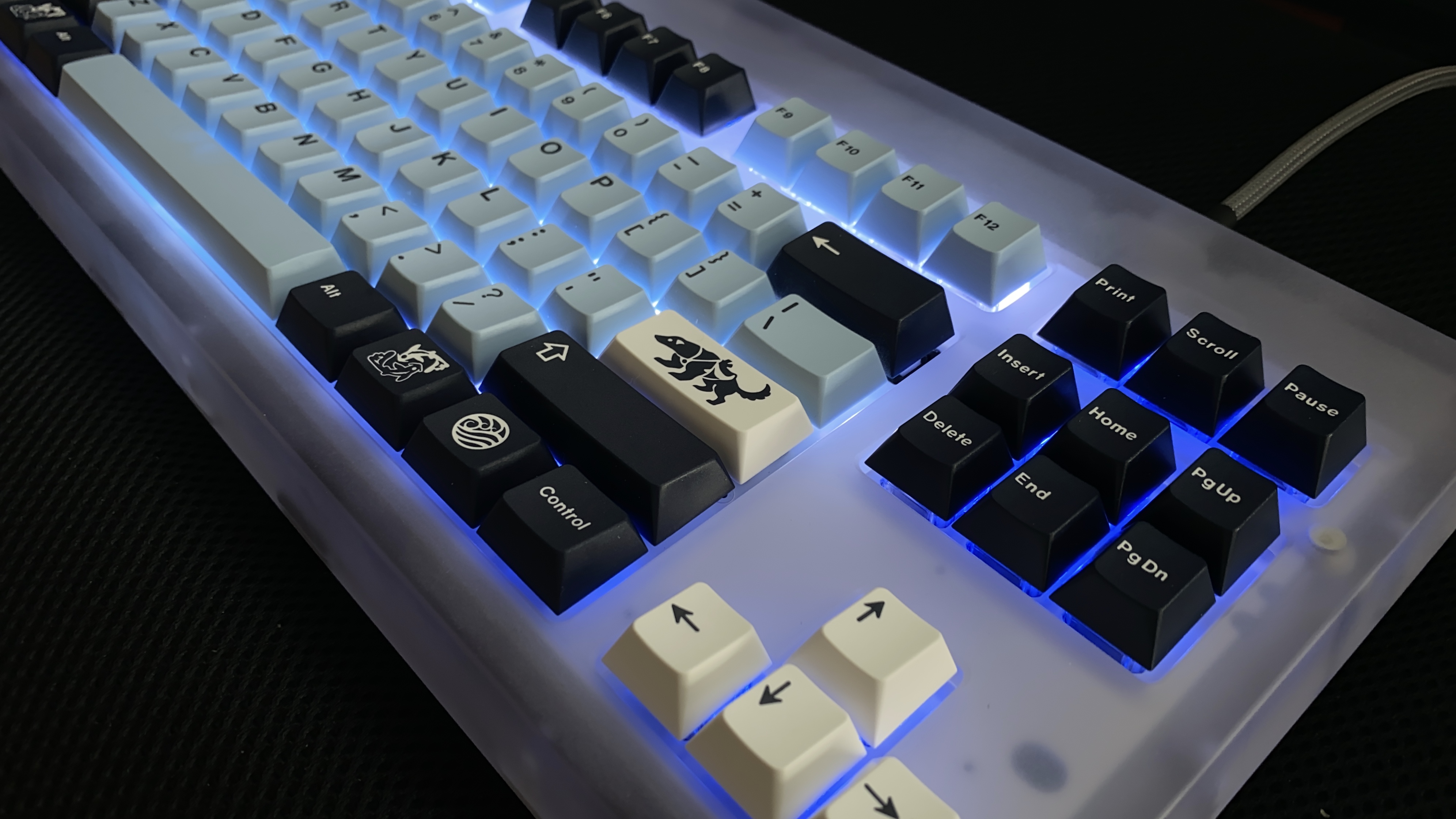
After downloading the Realforce software and configuring the board, it’s Thock Time. I was worried that the PC housing might sound a bit hollow, and it does, if the board is placed directly on a hard surface - but on a deskmat, it’s fine. I’m also pleased to report that the abrasive pads work as advertised; I was able to buff out a patch on the Norbaforce forehead to bring it back to a nice level of frost. Take it easy, though - you are definitely removing material with the most abrasive pad of the bunch.
Lessons learned
- If we’re trying to convince a person new to the hobby that lubing is essential for a premium experience, I’m beginning to think a Topre board makes the best argument for that proposition. The before/after difference in sound is amazing, and the actual lubing is significantly less time consuming for Topre than it is for a batch of MX switches, even allowing for the extra lube that has to be shoved into Topre stabs. No rattle, and smooth, deep thock.
- Deskeys #3 rings are doing more than the #2 rings to silence the board, for sure - but I think I could be happy going even further. I’ll have to try #4 and #5 rings soon.
- Along with Christo 111, which I’ve used with success on GMK stabs, Christo 129 works well for these stabilizers, and is a cheap lubricant - which is good, because you’re going to need much more of it for those Realforce R2 stabs. Yikes.
- If you’re not dome swapping your Topre board, it’s possible to leave the domes and springs in place and save a lot of build time - but it requires that you have your wits about you.
- The modest additional force the Realforce spacebar spring provides may not be worth the spacebar rattle it introduces, and it can be left out with no adverse effects.
- I wasn’t sure I’d necessarily like PC as a housing material, but the sound of this board is making me curious to try it again with MX-style switches.
This board was advertised as the “Ghost-of-Christmas-Future”, and I considered going for a holiday look when matching keycaps, but after seeing the RGB in action, I had to go with a luminous block of ice, and the shades of blue that implied. Or perhaps it’s Cerenkov radiation. A Christmas Carol redux, a frozen wasteland, or an exposed nuclear core? Choose your future Norbaverse.
Specifications
donor board: Realforce R2 RGB TKL
case: "Ghost-of-Christmas-Future Edition" polycarbonate Norbaforce Mark II
case dampening: n/a
PCB: donor
plate: donor
plate/PCB dampening: n/a
LEDs: per-key RGB in donor PCB
switches: stock Topre domes (45g)
switch mods:
- Tribosys 3204 on slider housing rails
- Deskeys #3 silencing rings on sliders
- removed Realforce spacebar spring
stabilizers: donor
stabilizer mods: Christo MCG 129 on all wire-housing contact points
keycaps: GMK Mizu (base, novelties)
HxWxD (without feet, risers, or caps): 0.88" x 15.13" x 7.13"
HxWxD (without caps): 1.25" x 15.13" x 7.13"
HxWxD: 1.63" x 15.13" x 7.13"
assembled weight: 1.26 kg (2.77 lb)
13 Likes
I should have read this sooner as I, like you, also applied bumpons prematurely in my haste only to have to remove them for the legs!
If you wrote for a publication I’d read every one of your articles.
3 Likes
Very nice build log, as always 
And a very nice selection of keycaps and lighting, very classy!
Ah Realforce keyboards, my second love 
Have one full size that is more than 10 years old and really love the tactility.
It is too bad to have to go to such modification extend with the R2, mine is quite silent out of the box … but would definitely benefit some lubing 
Capacitive technology does not have enough love of the custom keyboard community, really hope that Gondolindrim will soon flood the market with nice custom capacitive PCBs to change that.
2 Likes
Totally made my day. Thank you!
1 Like
Thank you! I’m also pretty excited about Gondo’s work, especially if it opens the door for QMK-compatible PCBs for existing housings. Early days, to be sure, but I’m optimistic…
2 Likes
Wow, I don’t know how I missed this thread… Oh the joys of working with Topre.
First time I did a dome swap on my 87U, I accidentally knocked the plate over (which was resting on the edge of two books…) and spent the next hour carefully searching for the extraordinarily light coil springs that went flying everywhere.
Will have to try out some lube on the RGB, sounds like it made a big improvement.
3 Likes
Build #37: Sirius
As I keep building, I’m finding the interplay of materials and sounds to be an especially interesting aspect of the hobby. It seems that nowadays, every GB offers an assortment of plate materials, ranging from flexible plastics like POM and polycarbonate, to softer metals such as aluminum, to rigid materials like brass. On the switch side, we see POM, nylon, ABS, and PC, in different combinations and blends for housings and stems. In combination, these materials can yield a wide range of sounds, from sharp clacks to dull thocks, sometimes in unpredictable ways, which keeps things interesting.
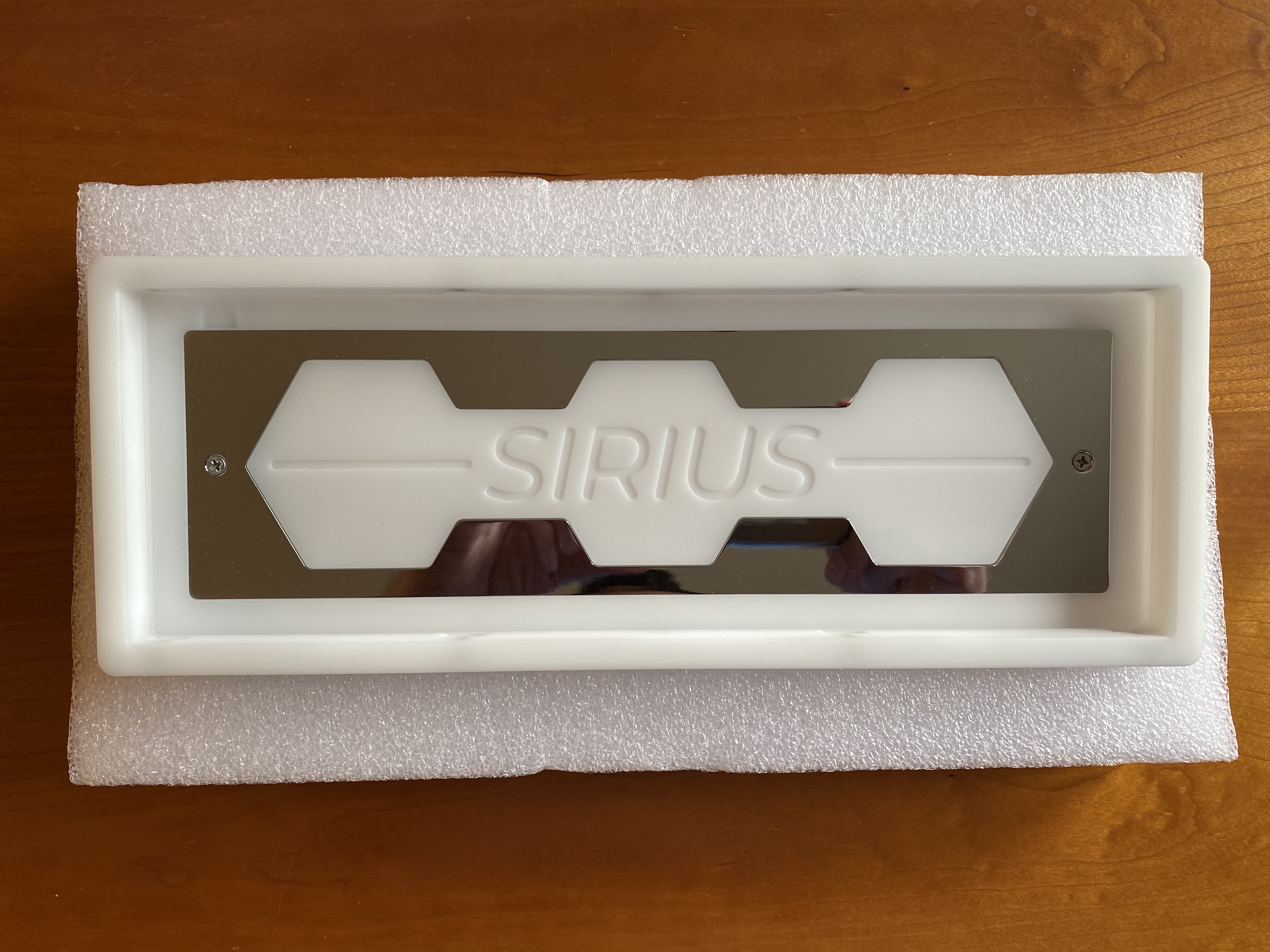
For keyboard housings, however, while we do see the occasional brass limited edition runs, or polycarbonate releases, the dominant material is aluminum. As such, from a sonic perspective, we start from a pretty familiar blank canvas for the lion’s share of our builds. So it’s nice when new options appear for keyboard housings. Enter the Sirius, a 60% housing made of POM (acetal).
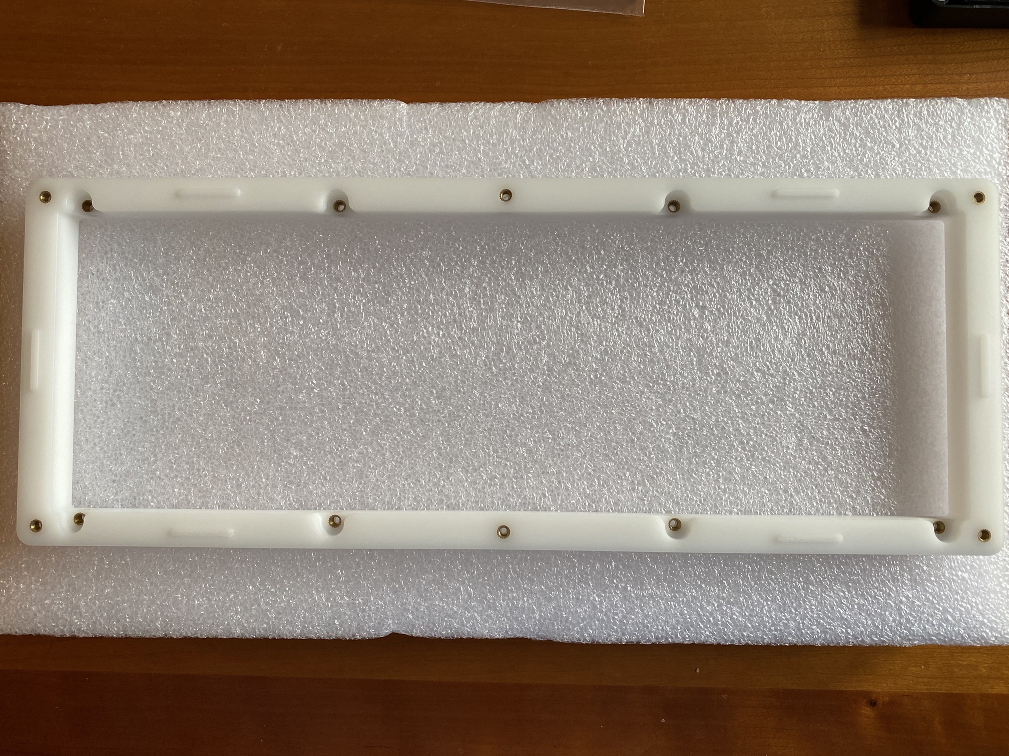
The only non-POM part of this case is the bottom weight, a PVD-coated brass with a silver finish. From this angle, we also see that the case bezels are relatively thick. This may be a plastic housing, but it’s by no means a flimsy one.
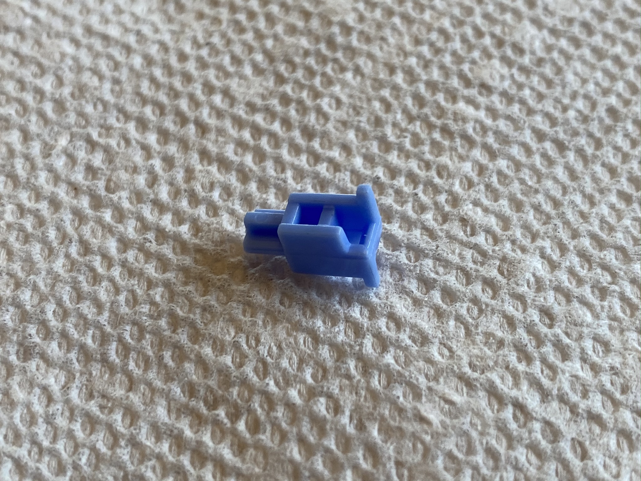
Time to build some guts. As usual, we start with stabs, in this case C3 screw-in stabs, with POM housings and stems. There are a few things I like about these stabs. First, they come with cloth washers, so if your choice of PCB needs washers to guard against shorts, you’re already covered. Second, the clips for the stab wires are quite tight; while it requires noticeably more force to snap the wires into place, it seems highly unlikely to me that these stabs would ever have the wire pop-out issues that some other stabs have.
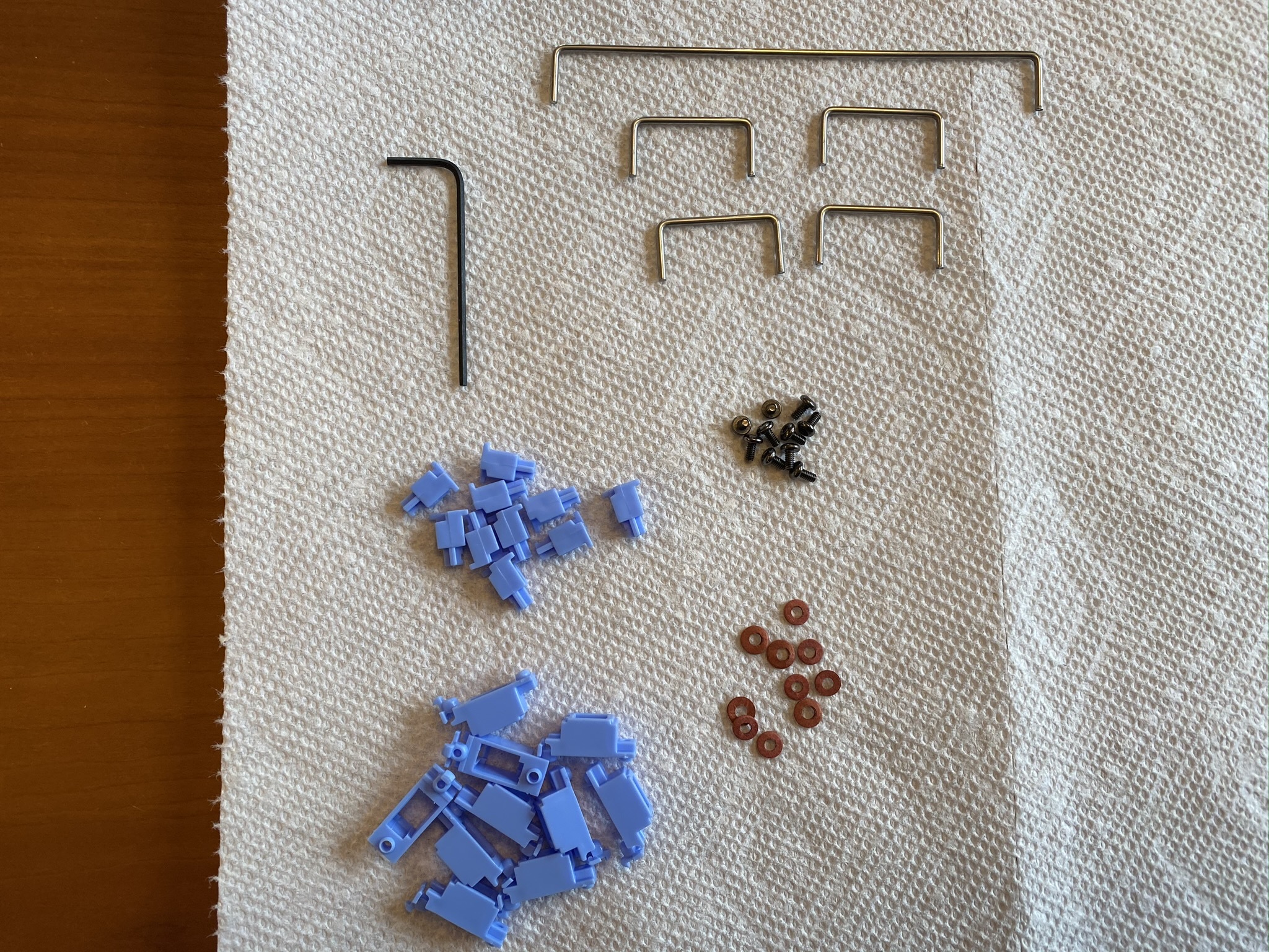
And, third, a small but nice thing - no clipping mod necessary, as there’s nothing to clip.
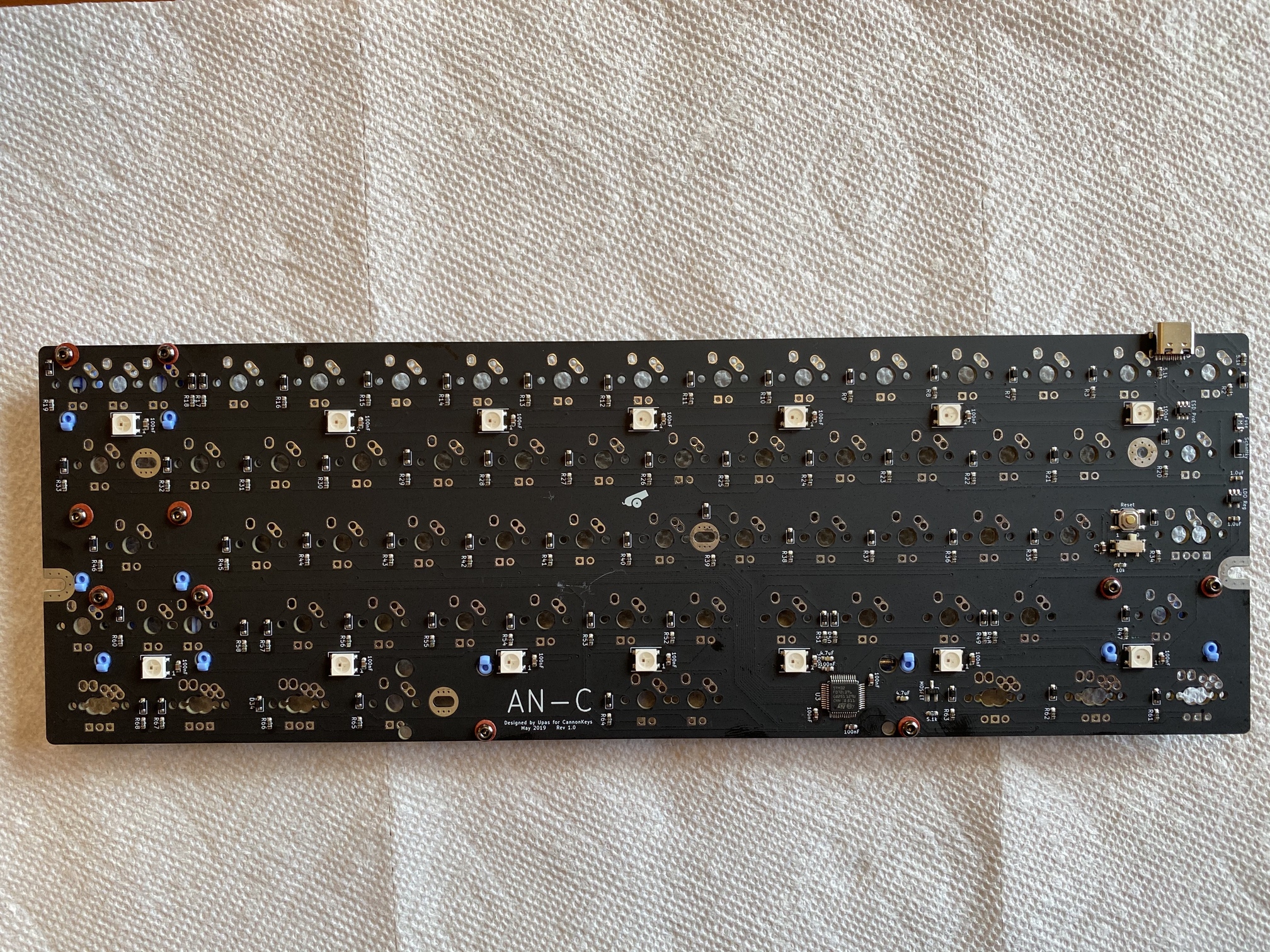
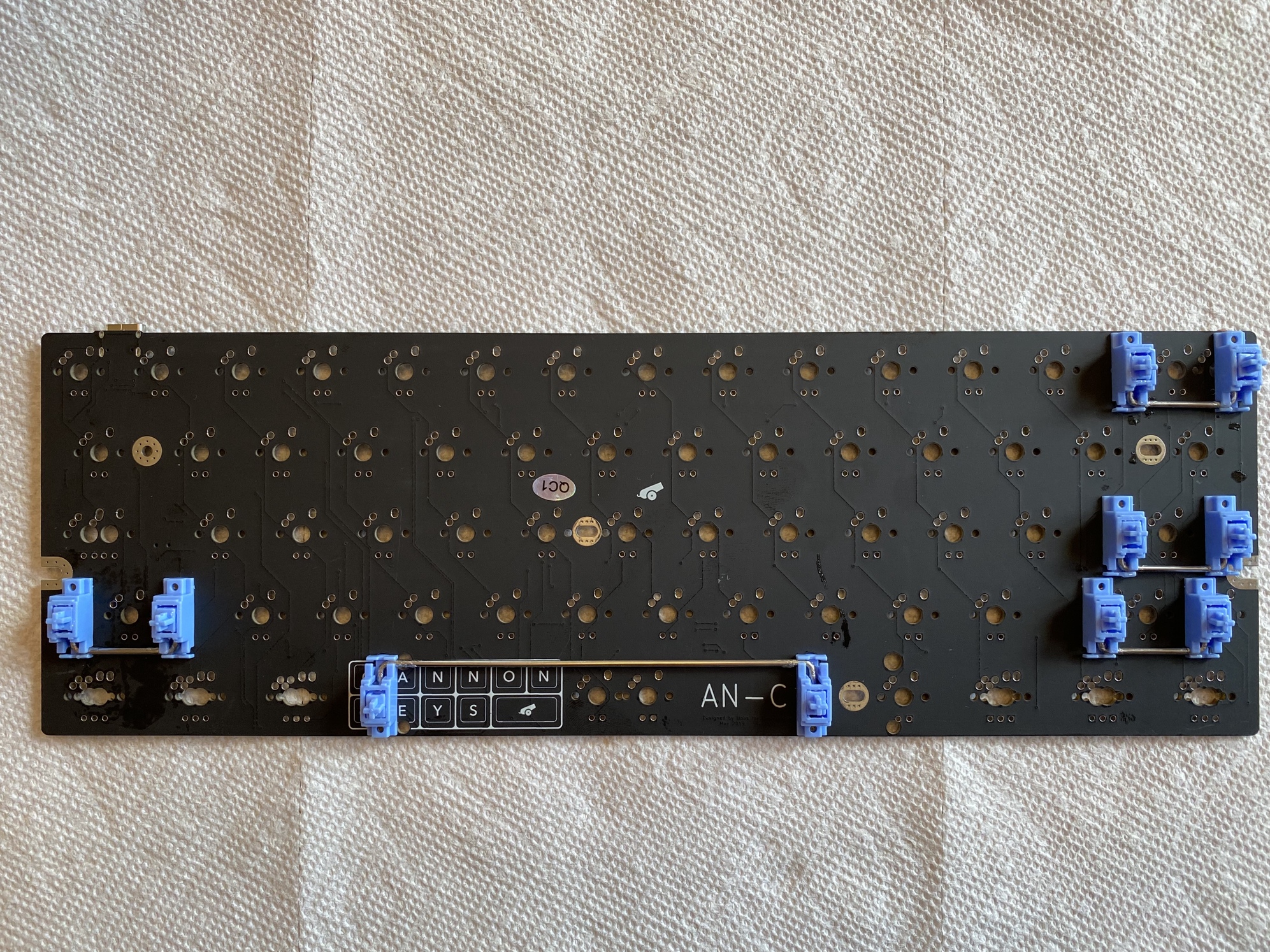
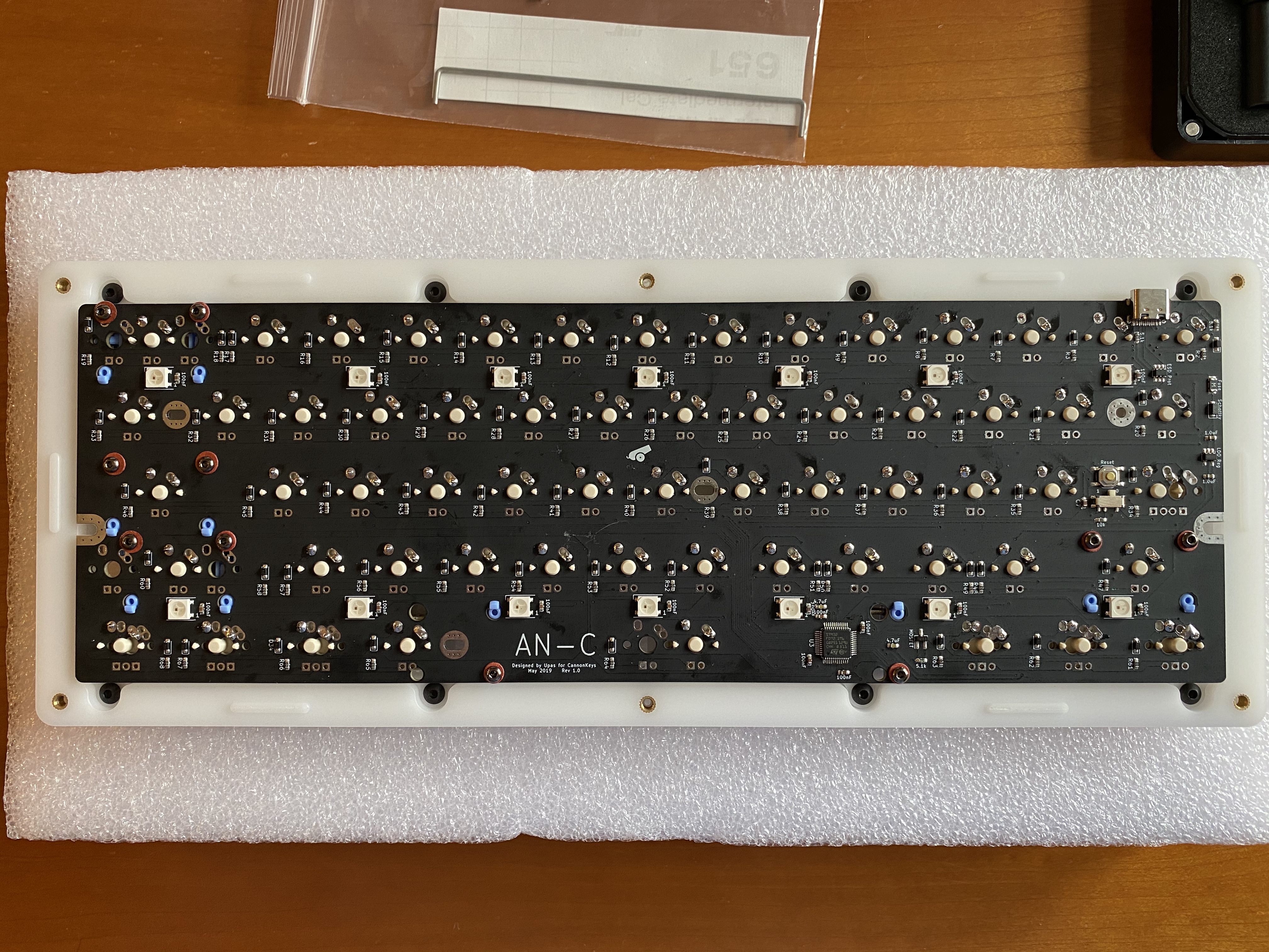
The Sirius kit shipped with the AN-C PCB from CannonKeys, an ARM-based PCB with RGB underglow and QMK/VIA support. Here’s a quick look the underside, with lubed and washer-installed stabs in place.
Note that underneath the reset button, just above the left-shift stab screws, there is a little white toggle switch. To put the PCB in flashing mode, you need to flip this switch to ‘1’ and hit the reset button right above it. After flashing, you flip the switch back to “0” and hit the reset button again. As such, you’ll almost certainly want to set a key combo to the QMK RESET code when you initially flash the PCB, so that you don’t have to open up the board and fiddle with this switch every time you want to flash it - or, you can flash VIA to the PCB, which allows you to configure straightaway.
Here’s the top side of the PCB. I managed to get a bit of SuperLube on the PCB while installing the stabs, as you can see above the right side of the spacebar stab - one reason why I build on top of a paper towel! (With the current sporadic shortages of paper towels in the grocery stores, I may be moving to washable tea towels for a while…)
The top-mount plate that came with the Sirius is also made of POM.
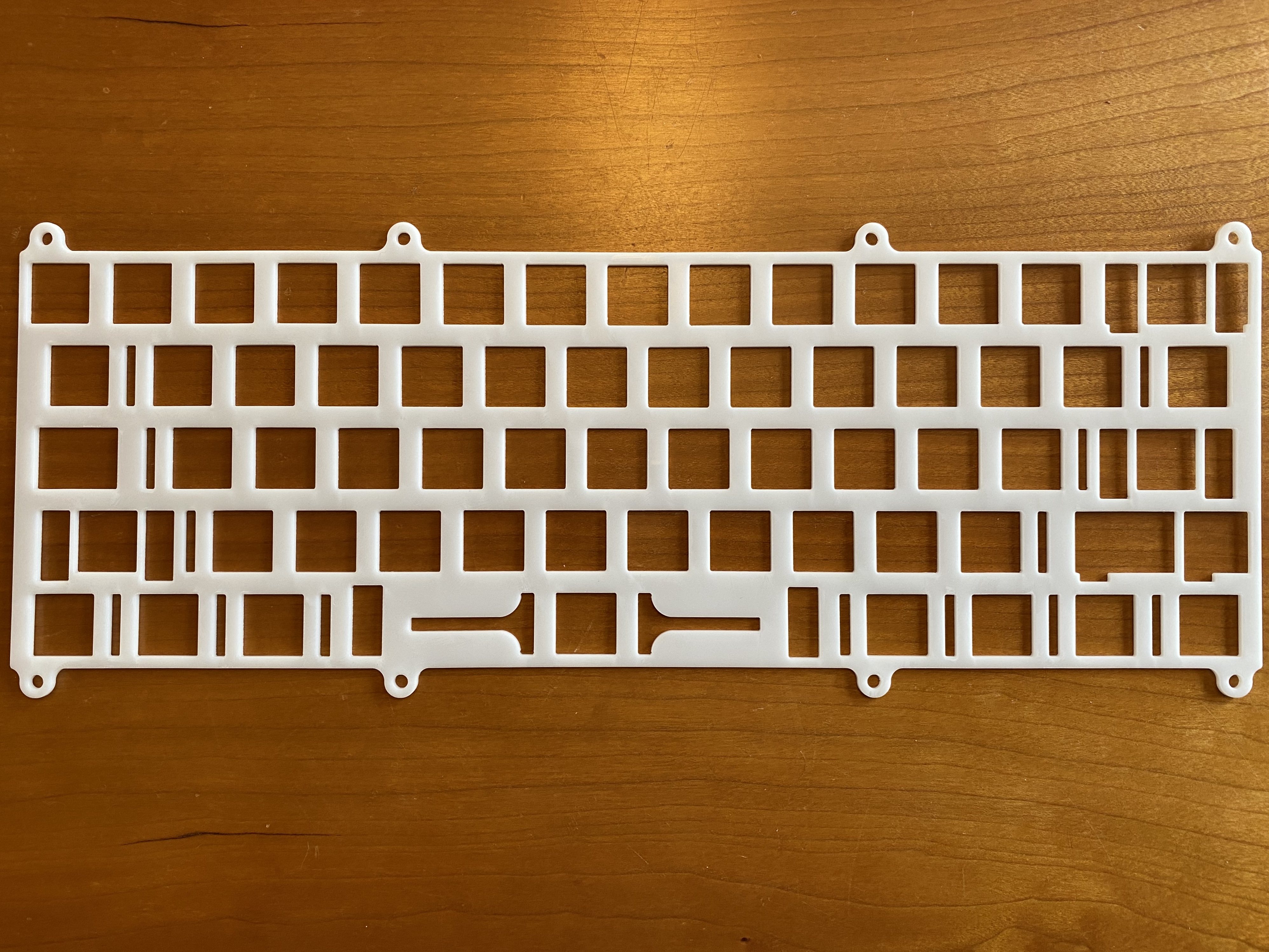
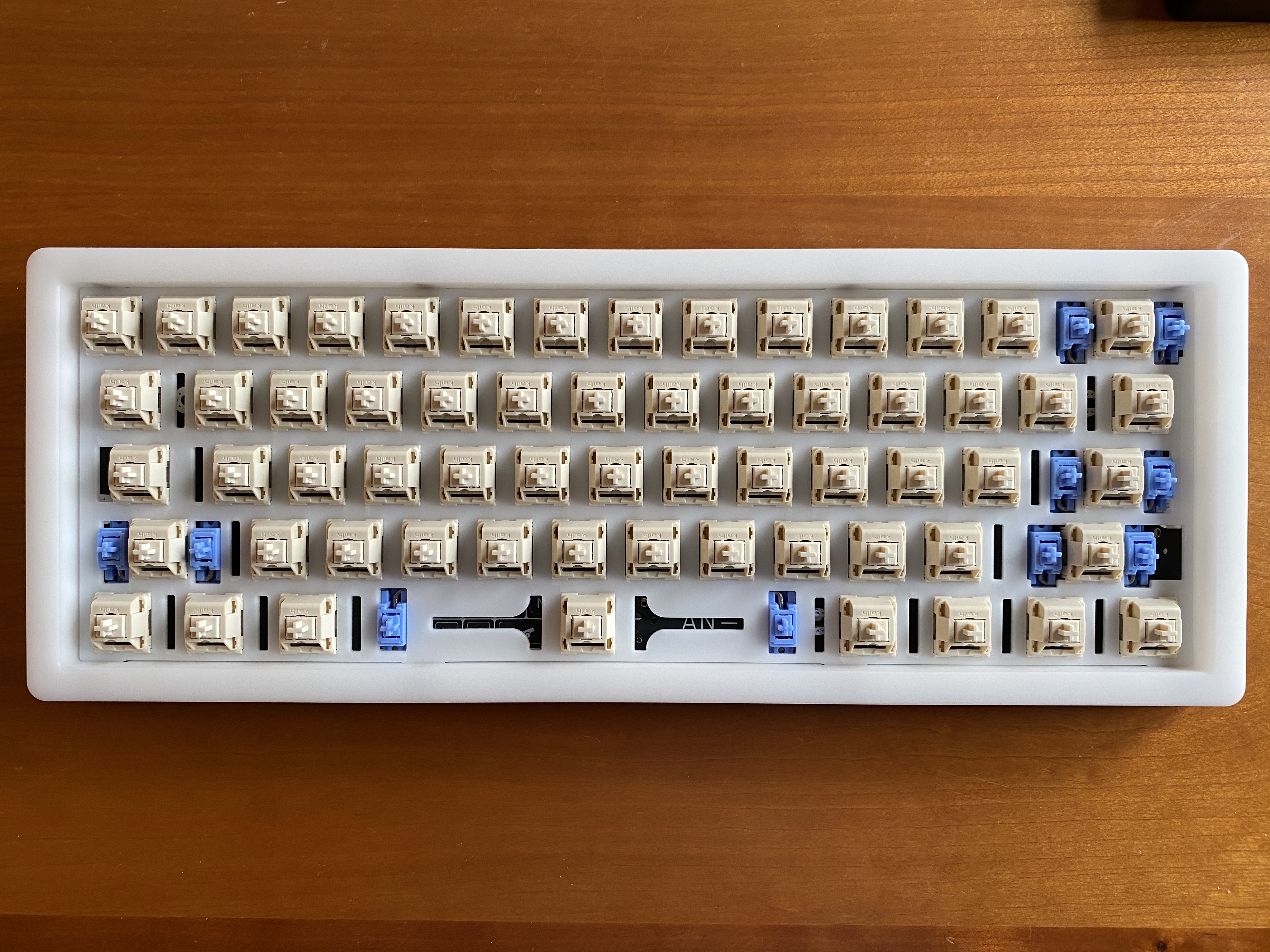
Because we’ve got a POM theme going, I opted to use NovelKeys Creams for this build, also made of POM. Since the POM plate is quite flexible, I found it easiest to place all the switches in the plate first, and then align the entire plate/switch assembly with the PCB before soldering.
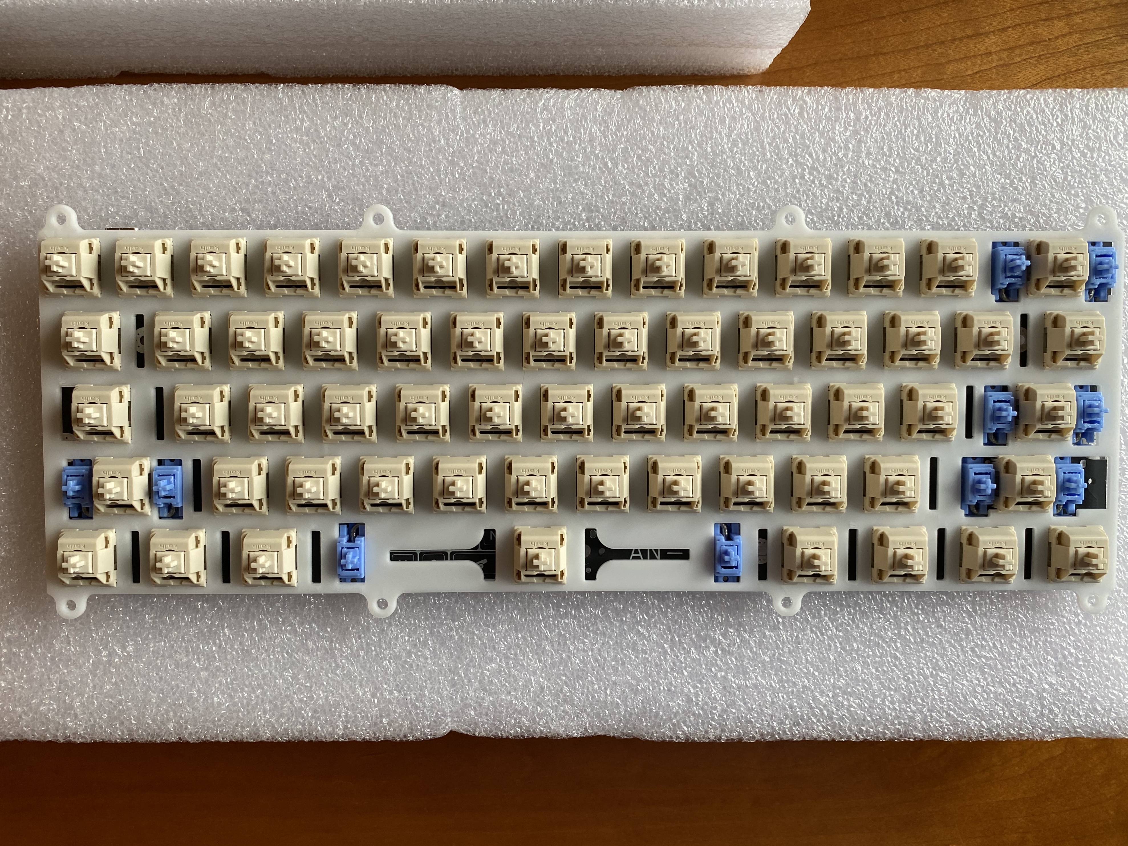
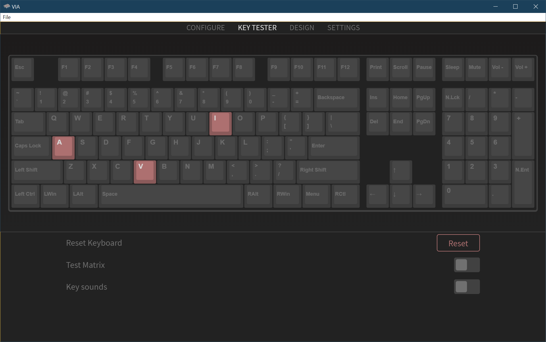
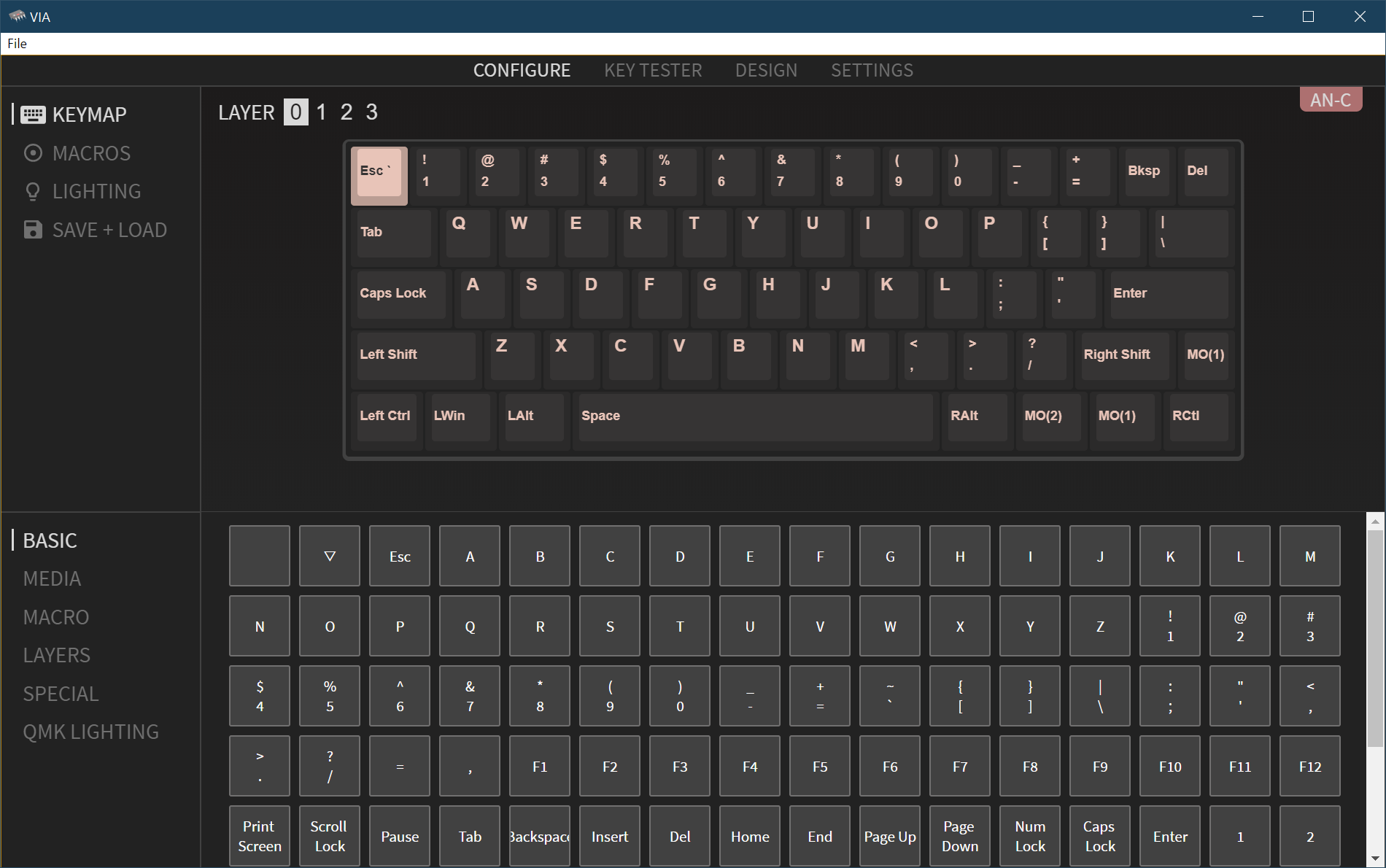
At this stage, I’d typically fire up Switch Hitter to check that all switches are functioning.However, in addition to using this build to explore the sonics of an all-POM board, I also wanted to check in on the current state of the VIA configurator, which now has its own built-in switch tester. After flashing the latest VIA firmware with QMK Toolbox, and installing the latest version of VIA (1.2.7 as of this writing), yes, we do indeed have a switch tester. That’s convenient, especially since Switch Hitter has been unsupported for quite some time now.
We’ll come back to VIA in a moment, but let’s get the board put together. Looking at the underside of the case top, we see the top-mount screw holes, as well as the holes for the screws that join the two case halves. We also see one other feature - the raised tabs, which allow for easy alignment of the case top with the case bottom. I always like to see this touch.
No burger mount here - just attach the PCB/plate assembly to the top of the case.
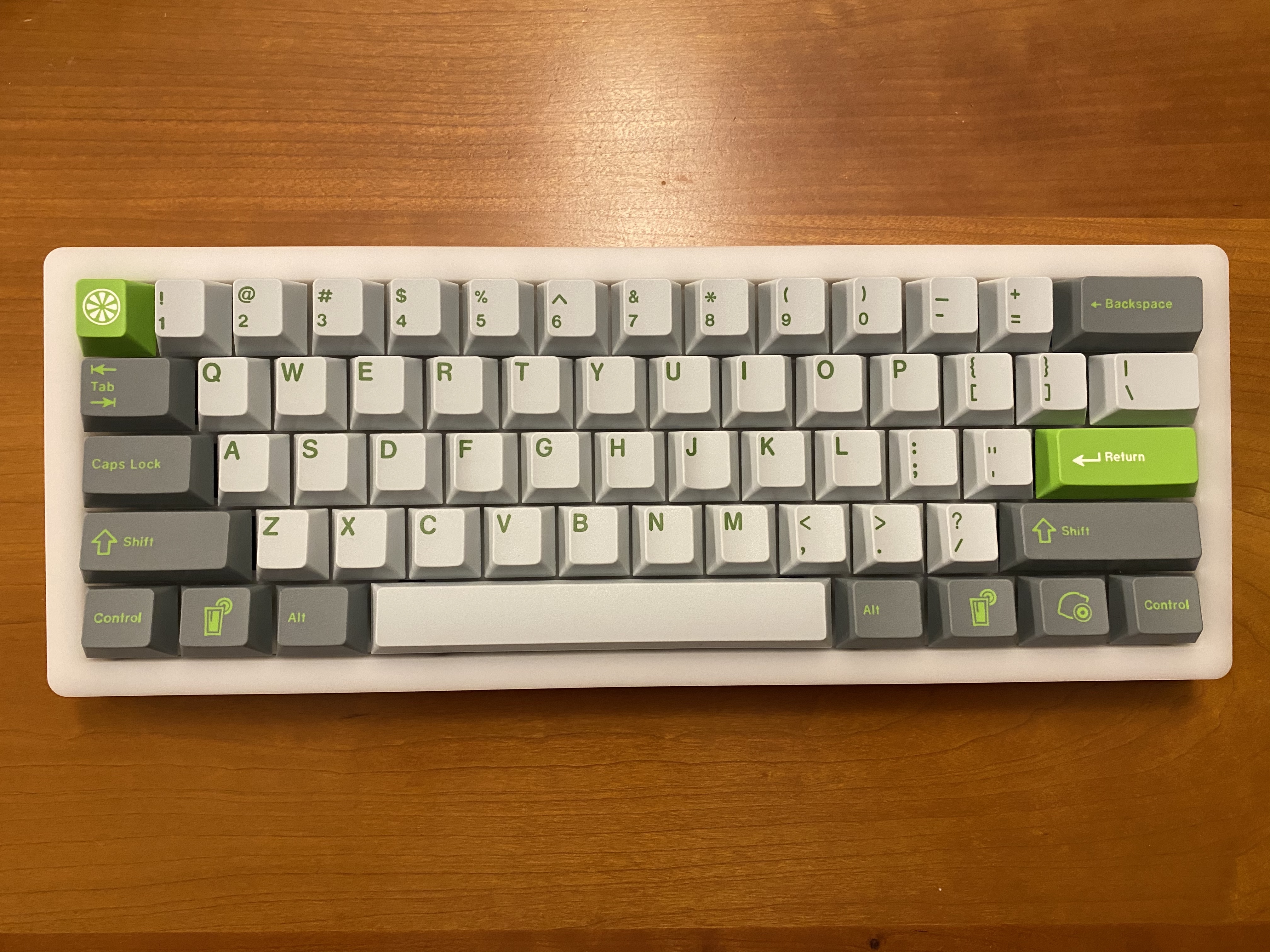
Screw the two case halves together, flip it over, and we’re ready for keycaps.
With keycaps on, I found the sound to be crisp, but with the harsh edge taken off. Nice. The only problem was that I was also hearing a sort of hollow-sounding “bongo drum” effect, so to deal with that, I opened the board back up, and put in a layer of craft foam, with roughed-out cutouts for the USB connector and reset button. Back together, and now we’re talking - nice, clean, crisp Cream sound, without any harsh edges.
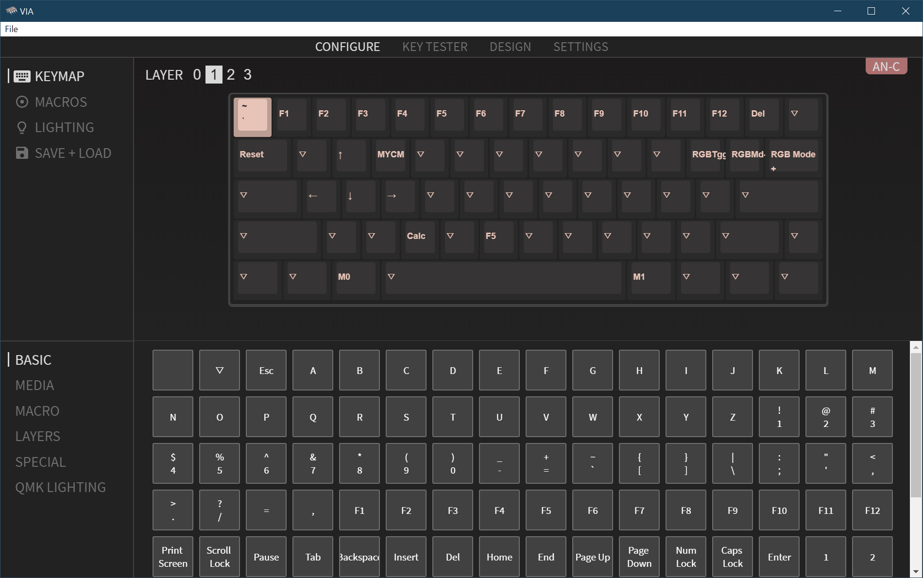
Time to see where VIA stands. The interface has been rearranged since I last played with it prior to the 1.0 release. The basic idea is the same as before; click on a layer and a key in the top half of the window, and click on its desired function in the bottom half of the window. The key is instantaneously programmed; no flashing necessary. I put MO(1) and MO(2) on the bottom row to give me access to layers 1 and 2.
To program the other layers, just select them at the top of the window, and proceed in the same way.
With that said, I wanted to try adding a feature that I use on every board I own that supports QMK; Mod Tap.
With the Mod Tap feature in QMK, you can have a key behave differently depending on whether it is simply tapped, or held down. I use this on the Alt keys. When held down, the Alt keys behave as they normally would, but when tapped, I have them send Ctrl-Win-Left and Ctrl-Win-Right, to allow me to switch between Windows desktops with a single keypress. This one feature has become nearly indispensable for me. But, so far, I have to add it to each build’s keymap by hand in QMK, and flash a custom firmware. While that’s not hard, I wanted to see whether I could replicate that functionality in VIA.
The answer is, close but not quite. I was able to create macros for the Ctrl-Win-Left and Ctrl-Win-Right chords, using the Macro menu on the lower left pane in VIA. Here, I’m assigning Macro0 to the “move left one desktop” key chord.
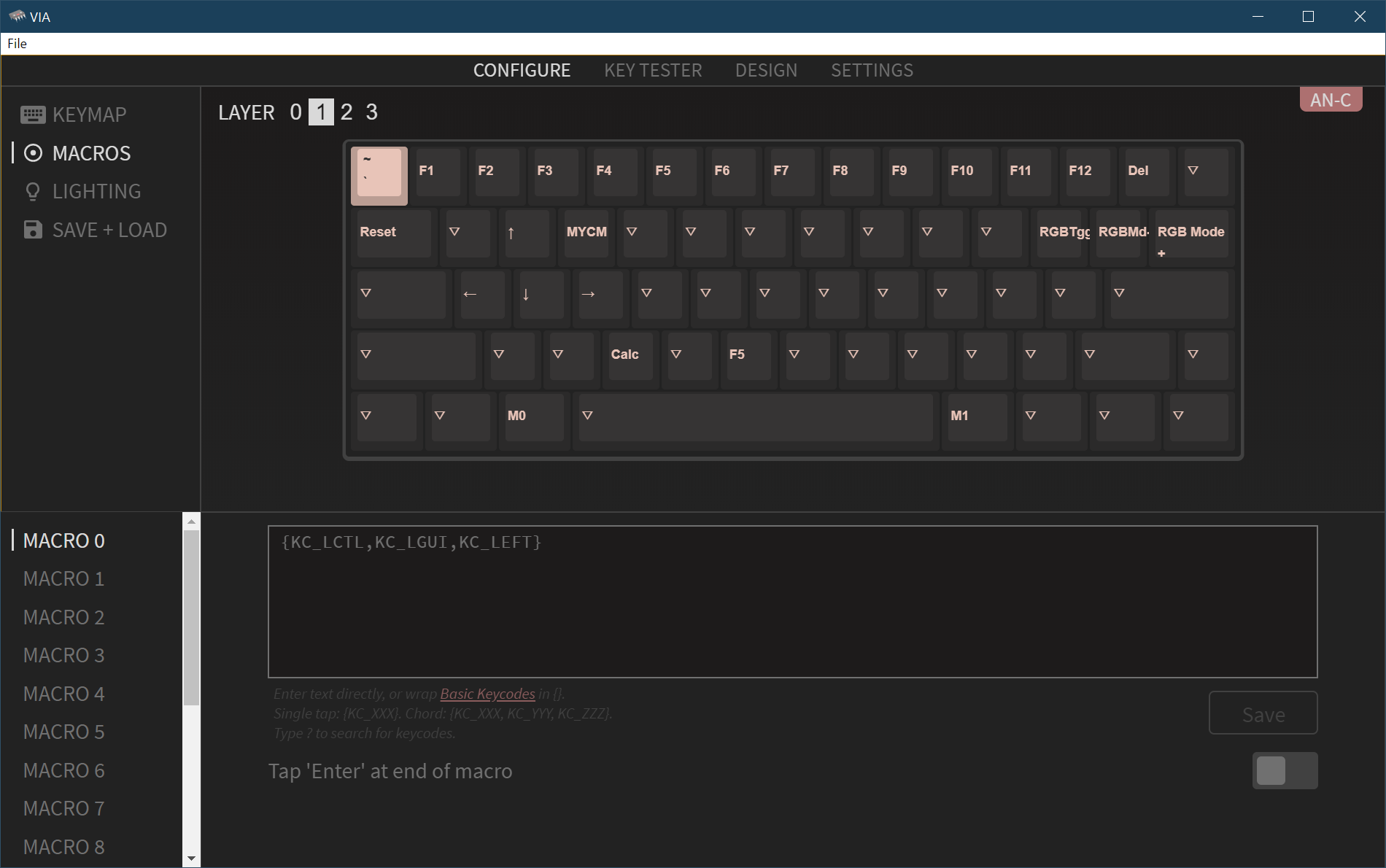
And, once that’s saved, I can return to the layer 1 keymap and assign left Alt and right Alt to the macros I just created.
So, that’s closer, but still not a single keystroke. I have to hold down one of the MO(1) keys and tap Alt to switch desktops. I could instead put M0 and M1 on the Alt keys in layer 0, but then I’d lose normal Alt functionality. Apparently it’s almost possible to enter mod tap sequences using the “ANY” key in the “SPECIAL” menu, but that feature currently has some bugs.
With all that said, VIA is progressing quite nicely. I wasn’t able to do macros before, which is a big step forward, and the number of boards that VIA supports seems to be growing daily. Soon…
Lessons learned
- An all-POM board (well, OK, as all-POM as we can get) has a lovely sound, almost like rapping your knuckle on a very thick plank of wood. As I said before, clean and crisp, but not harsh. I see why many people have been raving about the board’s sound.
- C3 stabs have been getting mixed reviews, but between this build and others, I find they take well to either SuperLube or Christo 129, and the tight wire clips are appreciated. I don’t see any reason not to use these.
- VIA is getting closer to supporting all of my personal hit list of features. While part of me will always be happy doing some C coding, another part of me will be happy when I can install my favorite QMK features on the fly using a nice GUI.
- Pretty sure this is my first time using Creams? With a thin coat of 205g0, nice sound and feel, but now I need to understand how much of that is the switch, vs the all-POM environment in which it was deployed.
- With that said, now I really want to build a Sirius with tactiles…
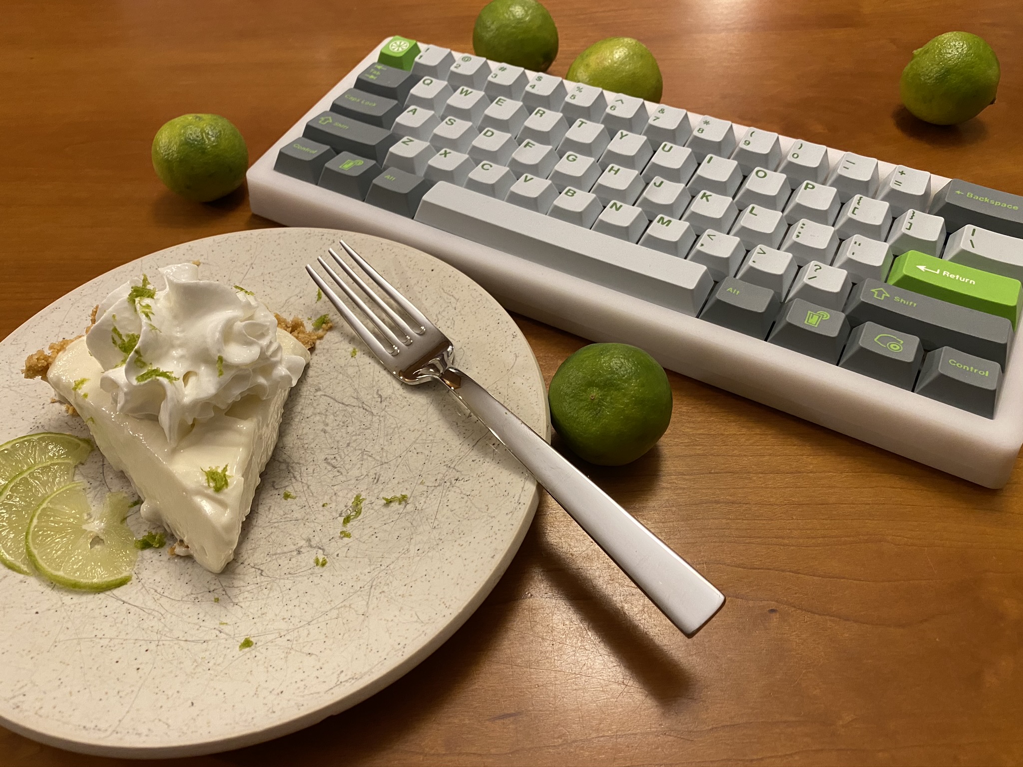
I see the appeal of the Sirius as a travel board; if you don’t mind scuffs and scratches, which the POM will certainly acquire, you can have a very nice typing experience in a comparatively lightweight board. But, with travel at a standstill, perhaps the better news is that you can still have that nice typing experience at home. Think of it as a “comfort food” keyboard. For me, one of those comfort foods is a homemade key lime pie. Mmmm…
Specifications
case: Sirius
- POM top (standard layout)
- POM bottom
- PVD brass weight (silver)
case dampening: n/a
PCB: AN-C 60
plate: POM ANSI
plate/PCB dampening: n/a
stabilizers: C3 screw-in
- blue, 1x6.25u, 4x2u
stabilizer mods:
- lubed with SuperLube
- installed with cloth washers
switches: 61x NovelKeys Creams
switch mods:
- springs tub-lubed with Krytox GPL 104
- stems hand-lubed with Krytox GPL 205g0
- no housing lube
keycaps: GMK Lime (base kit)
HxWxD (without caps or feet): 1.31" x 12.13" x 4.63"
HxWxD (without caps): 1.44 x 12.13" x 4.63"
HxWxD: 1.69" x 12.13" x 4.63"
assembled weight: 1.10 kg (2.43 lb)
10 Likes
Great build log as usual bud! I agree that there is no reason to not use C3 stabs. I’ve had a set on my T60 since I got them & find them to be on par with pretooled GMK stabilizers with the added benefits you mentioned. Also VIA is getting there! Merlin has been adding a ton of boards lately & more advanced QMK features have been getting added with each new version. If they keep up the updates I could see VIA becoming more used than QMK config/toolbox by the end of the year!
2 Likes
Very nice build log!
I always appreciate the last picture of your builds, always with a great scenery.
You are definitely a man of taste
Lime keyset is a very good choice for this build, too bad we don’t see them much on other builds because the colorway is really nice.
Still have some Maxkey SA Lime keyset (matte R2 version with no color issue of R1) waiting for a build, maybe in the near future …
1 Like
Keep it up!
1 Like
Stay tuned - depending on accuracy of delivery estimates for some parts and materials I need for the finishing touches, I have something to write about soon™ that may be of particular interest…
5 Likes
Ok, playing it mysterious I see…  Putting two & two together I’m gonna guess a Klippe-S or Type-X? Whatever it may be I’m looking forward to it! You’ve been putting out the best build logs in the community right here IMHO!
2 Likes
Build #38: Polaris
So, remember that red kbd67 with GMK Jamon? It turned out to be a hit - not only with its owner, but with her spouse as well, who asked me to build a board for him. His guidance: “make it Laker themed”.
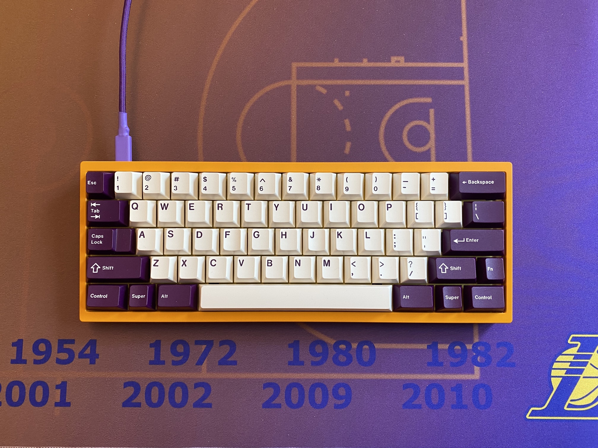
Normally, when I aim for thematic consistency in a build, I’m not targeting a specific color scheme or look; I’m usually surveying the available options to find parts and materials that look as though they belong together. But in this case, “make it Laker themed” can only mean one thing: the iconic yellow and purple of the Los Angeles Lakers basketball team. Prior to the recent explosion of case and keycap options in the hobby, this could have been a difficult request to fulfill.
But, sometimes, we just get insanely lucky. At the time I received this build request, the Polaris GB and the GMK Violet on Cream GB were almost closed…but not quite! So, after a quick flurry of back-and-forth emails, and two quick GB orders later, the long wait began months ago - and, finally, ended with the arrival of the Polaris. Let’s get to work!
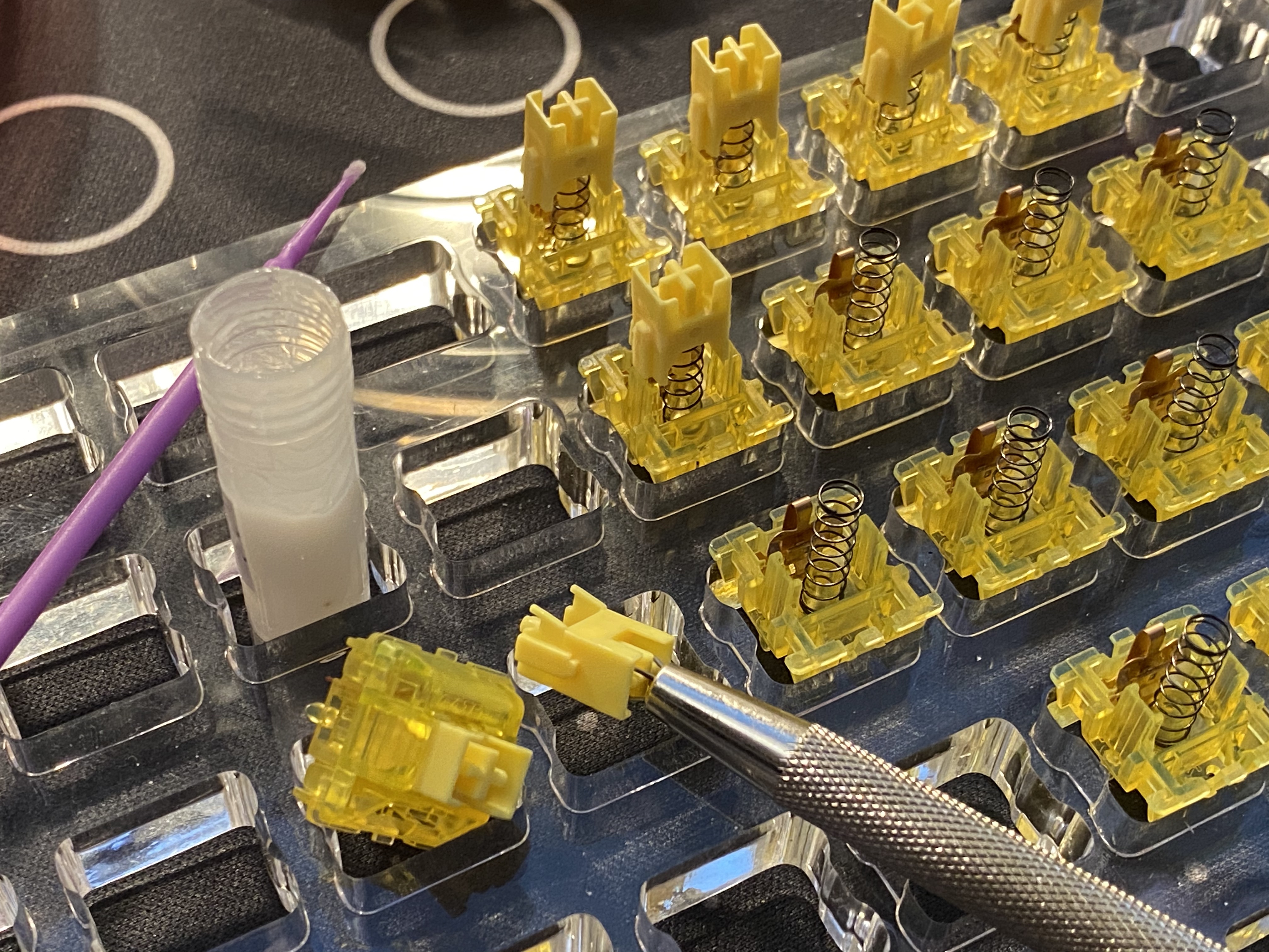
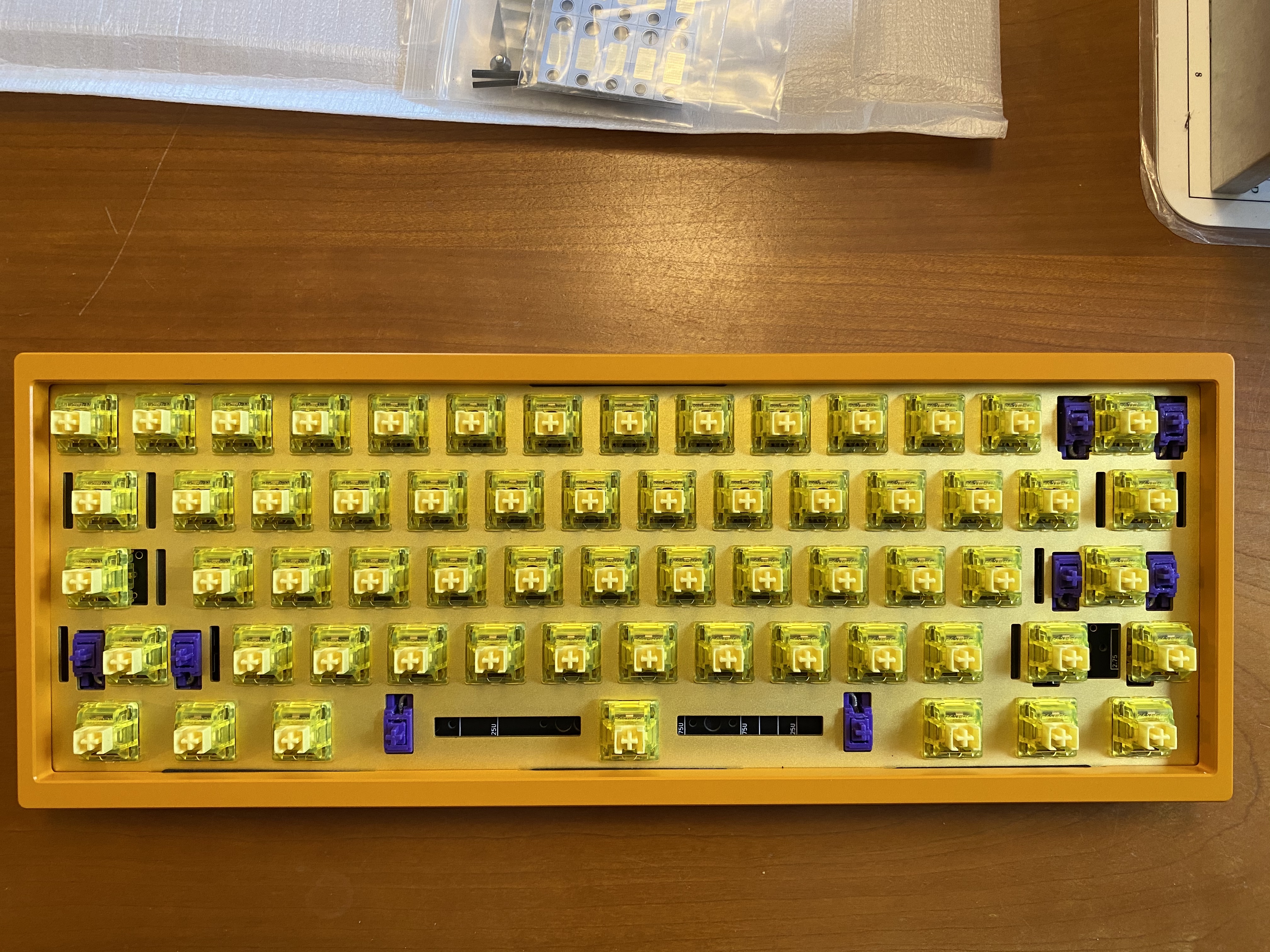
After showing him a few online typing tests, he wanted something with roughly the same spring weight as the 67g V2 Zealios on his wife’s board, but with a bit less clack and pop. I translated that to a request for mid-weight linears, and thought we might as well carry the color theme through to our switch selection. Time to lube some Gateron Yellow Inks. First step, disassembly, to tub-lube the springs with 104.
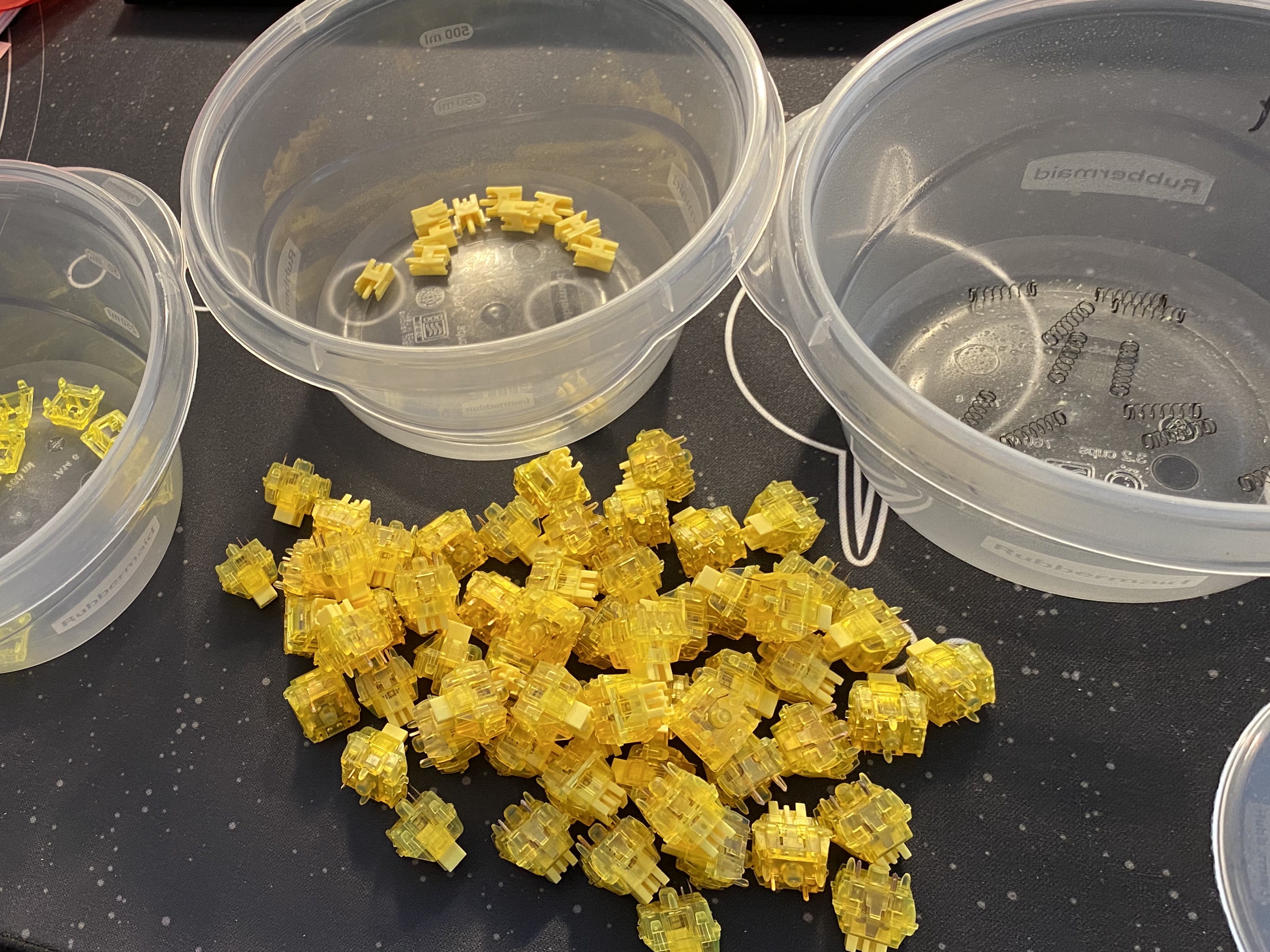
Since this was my first time working with box switches, I wanted to stay away from 205g0 and any potential overlubing issues, which left 129 and 3203 as candidate lubes. Between those two, I find 129 takes rattle away but otherwise has little effect on sound, whereas 3203 takes a touch of the high-end clack away. Given the expressed sound preferences, I chose 3203. Let’s lube.
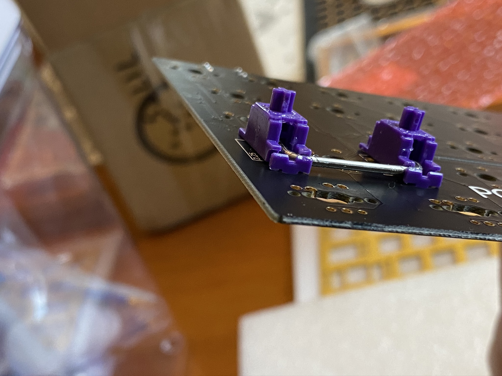
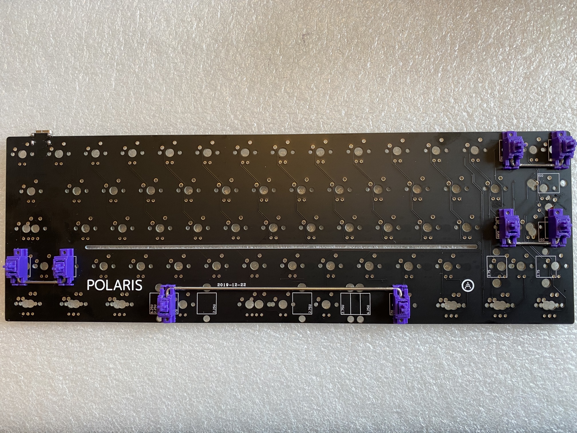
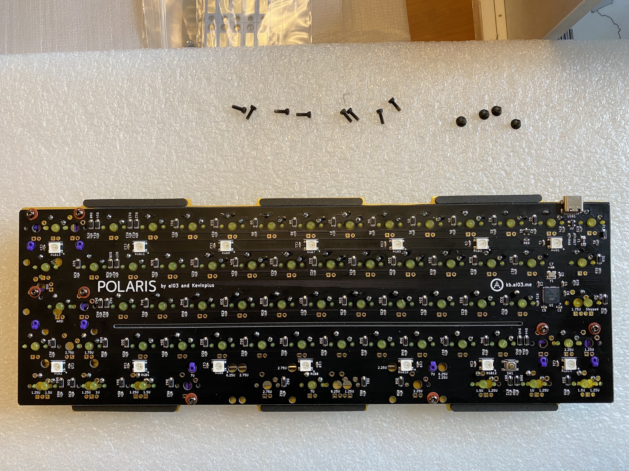
Great, 61 switches later and we’re done. If only it were that fast in real life. Before we move on to stabilizers, let’s take a look at the Polaris PCB. Already, I see one thing I like - clear markings for stabilizer housing placement.
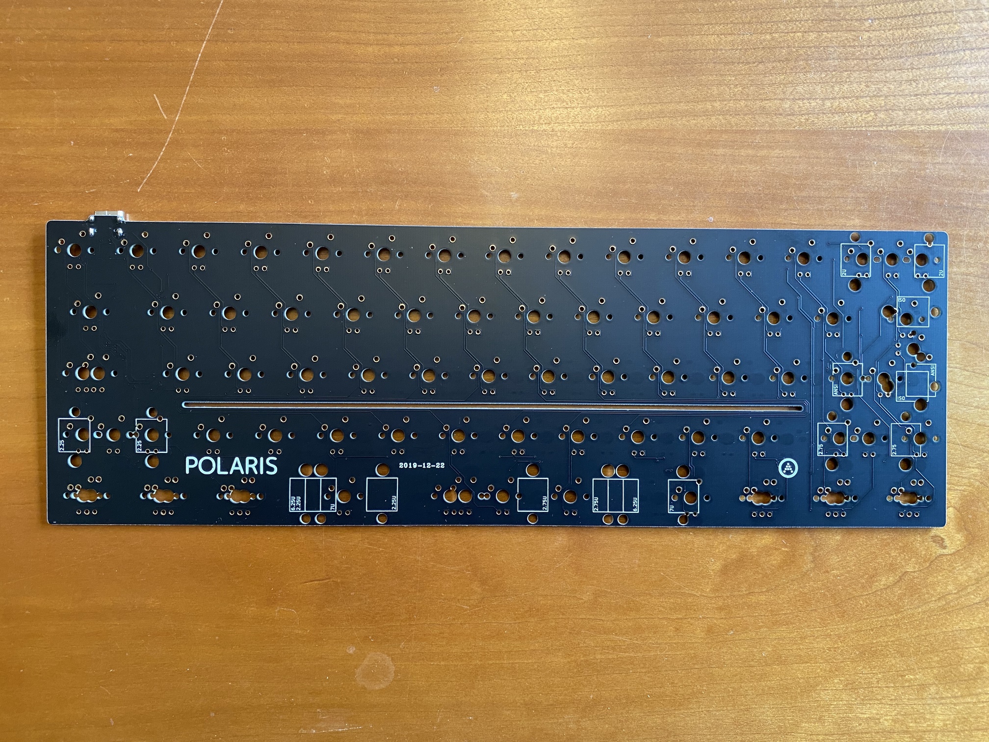
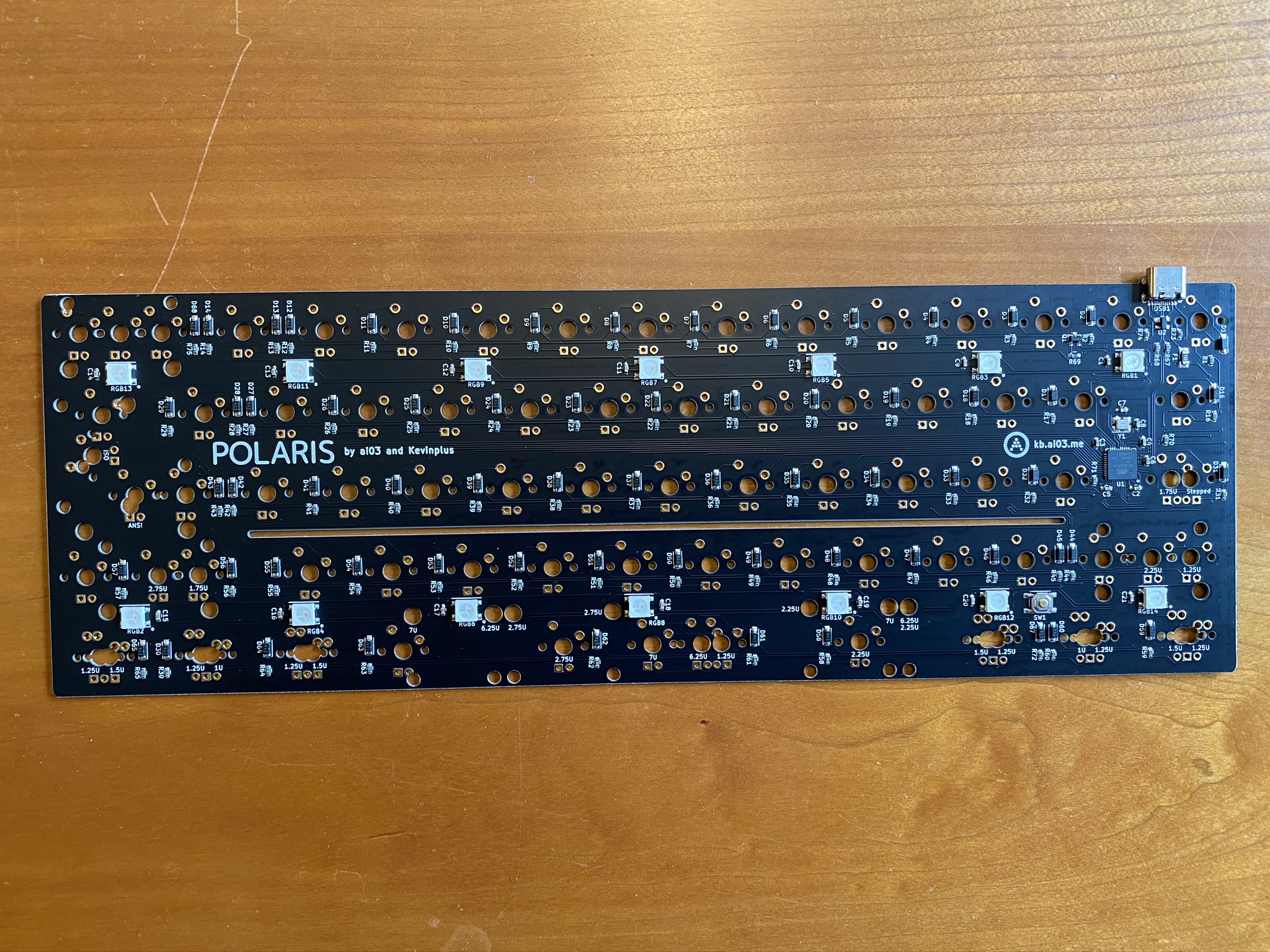
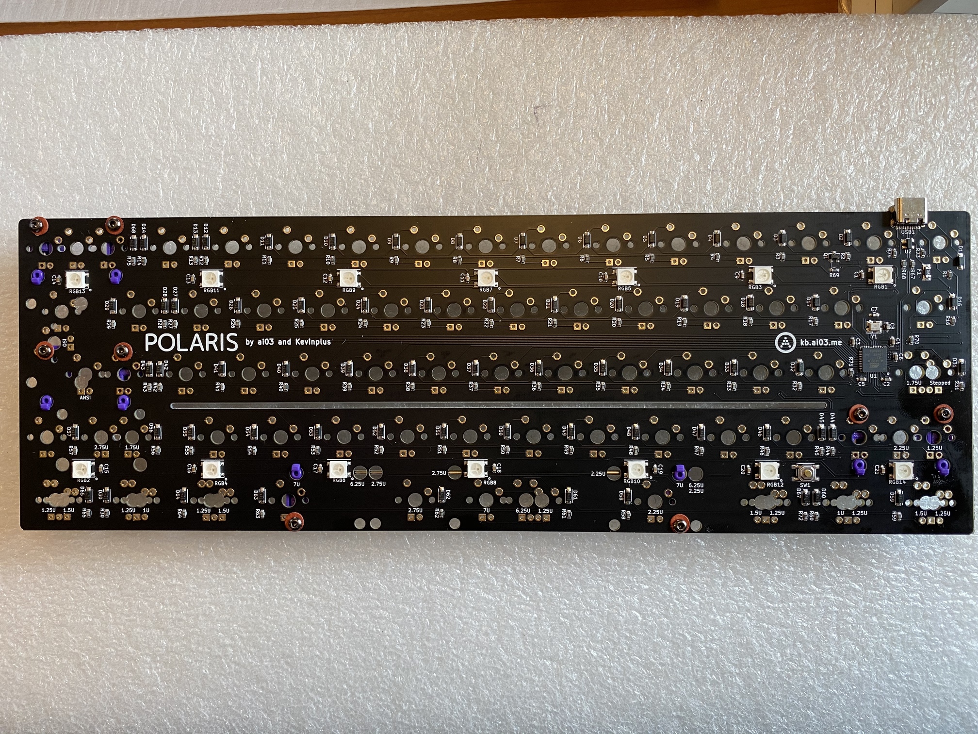
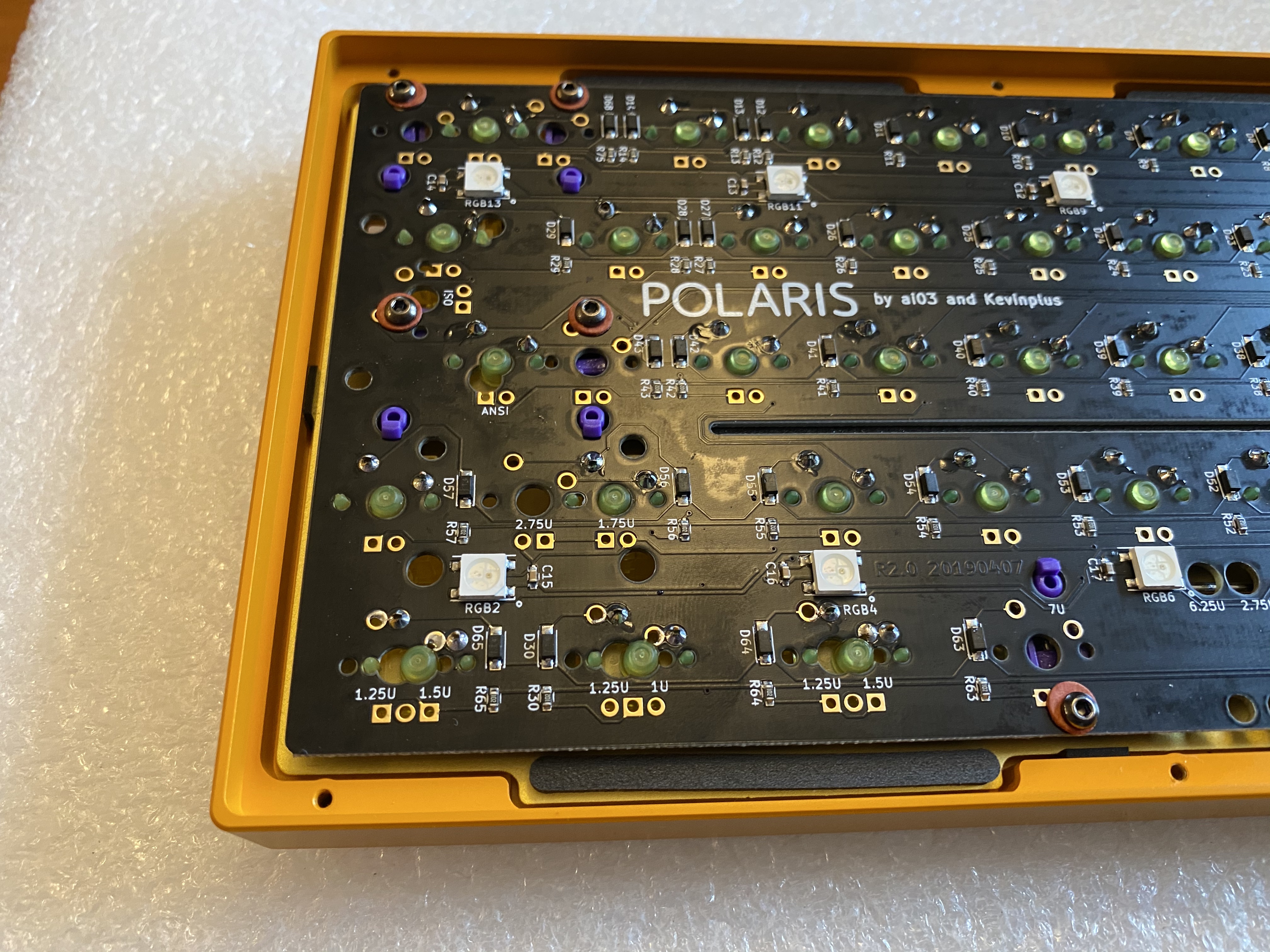
On the underside, you’ve got your RGBs and a USB-C port, and although there’s less room for labeling, there are still markings for all of the stabilizer options on this side as well. I approve. Another notable feature is the single relief cut running horizontally across the PCB.
C3 stabs are available in purple. Have to keep the theme going, right? The Polaris ships with spacers, as some stabilizers need the extra thickness to seat properly on the thin Polaris PCB.
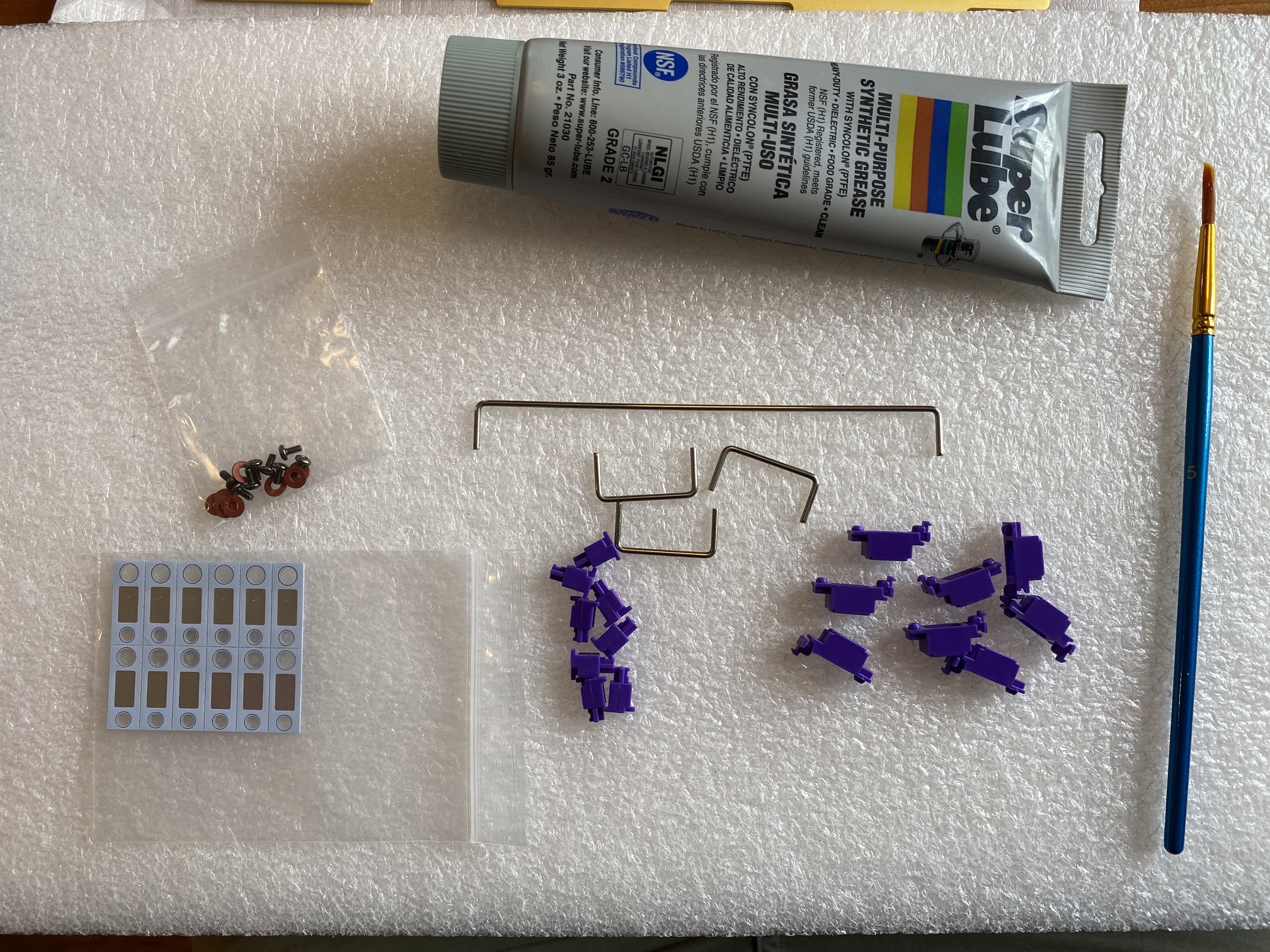
After trying both ways, the C3 housings were just thick enough to make it impossible to use the spacers, so I left them out. No issues.
Technically, black and white are also part of the Lakers color palette. Just saying.
I’m in the habit of using cloth washers on every build that uses screw-mount stabilizers, so it’s nice that the C3 stabs ship with their own washers. It saves me from rooting around trying to find where I’ve misplaced my own little plastic bag of washers, which I seem to lose after every build. I don’t know why that is.
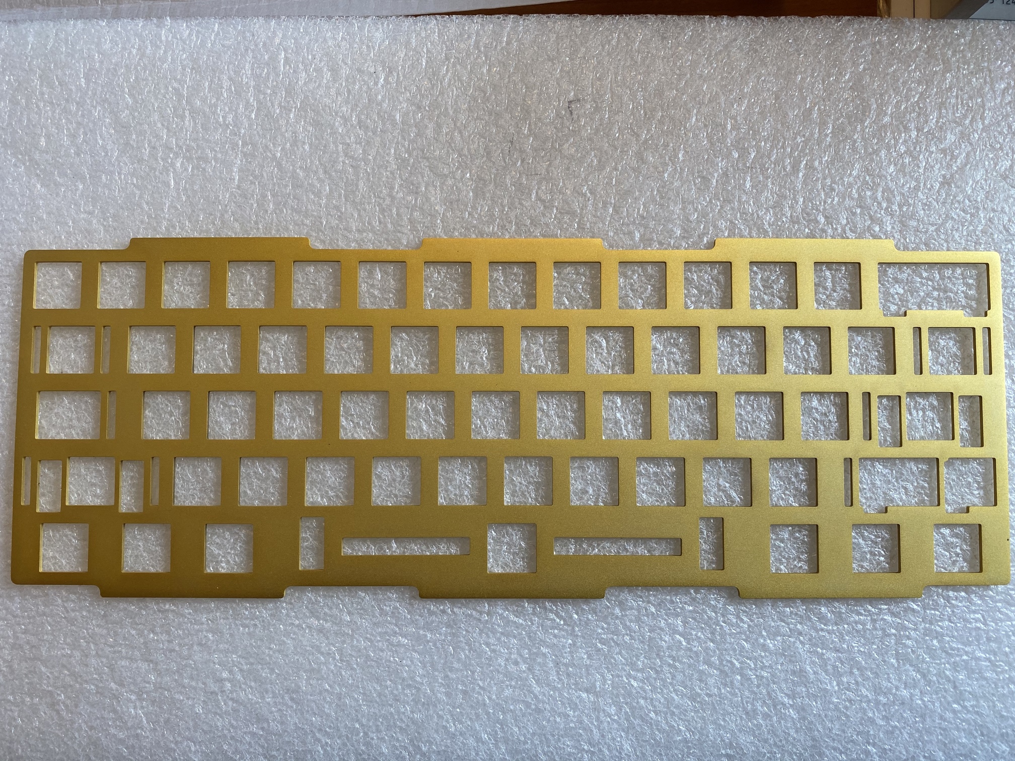
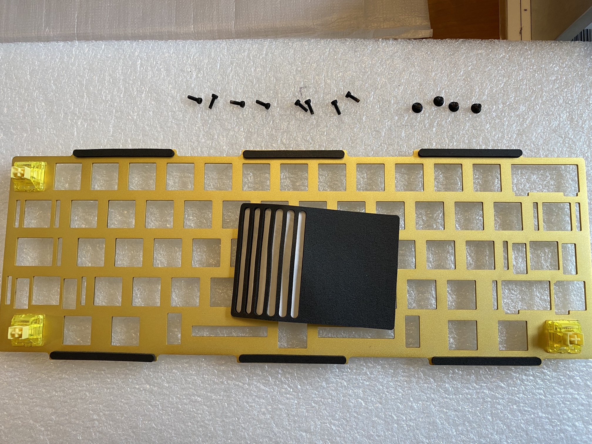
The Polaris brass plate has a nice matte finish, with some simple relief cuts flanking the modifier keys and under the spacebar.
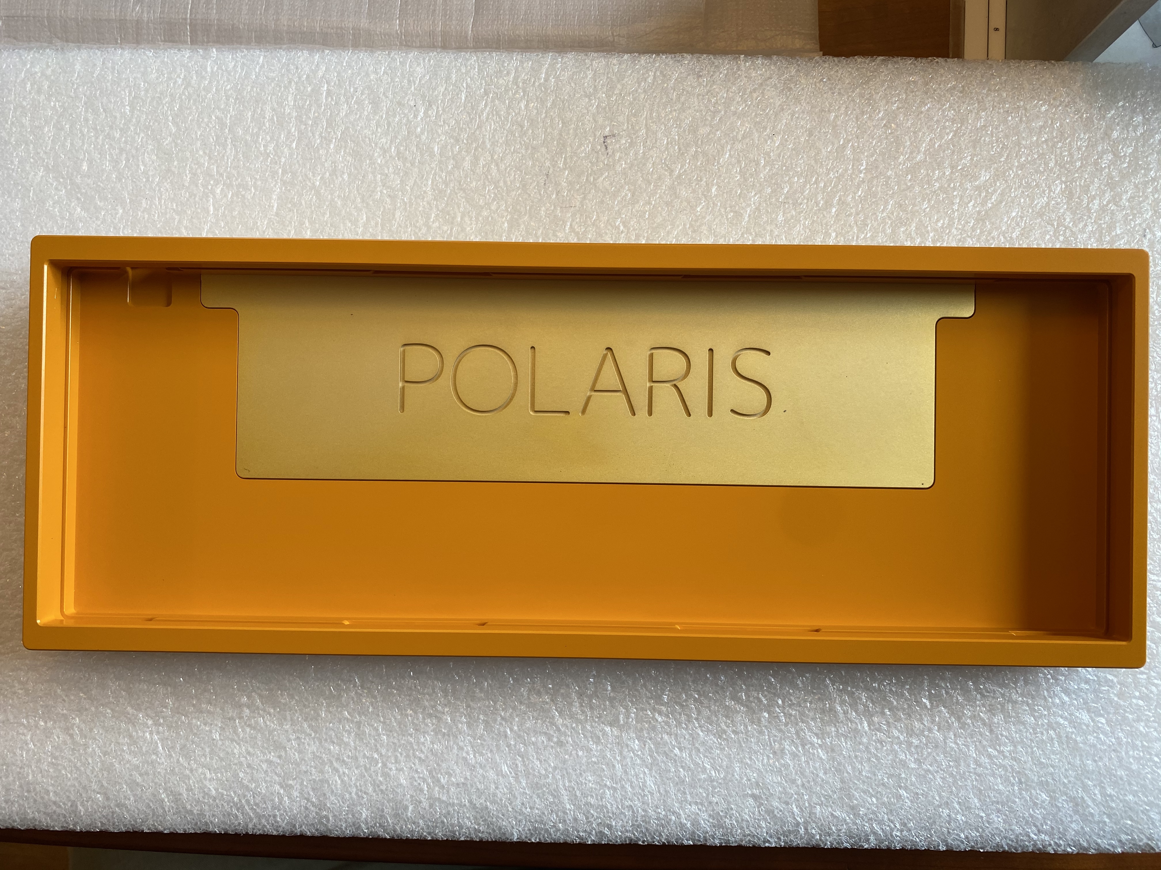
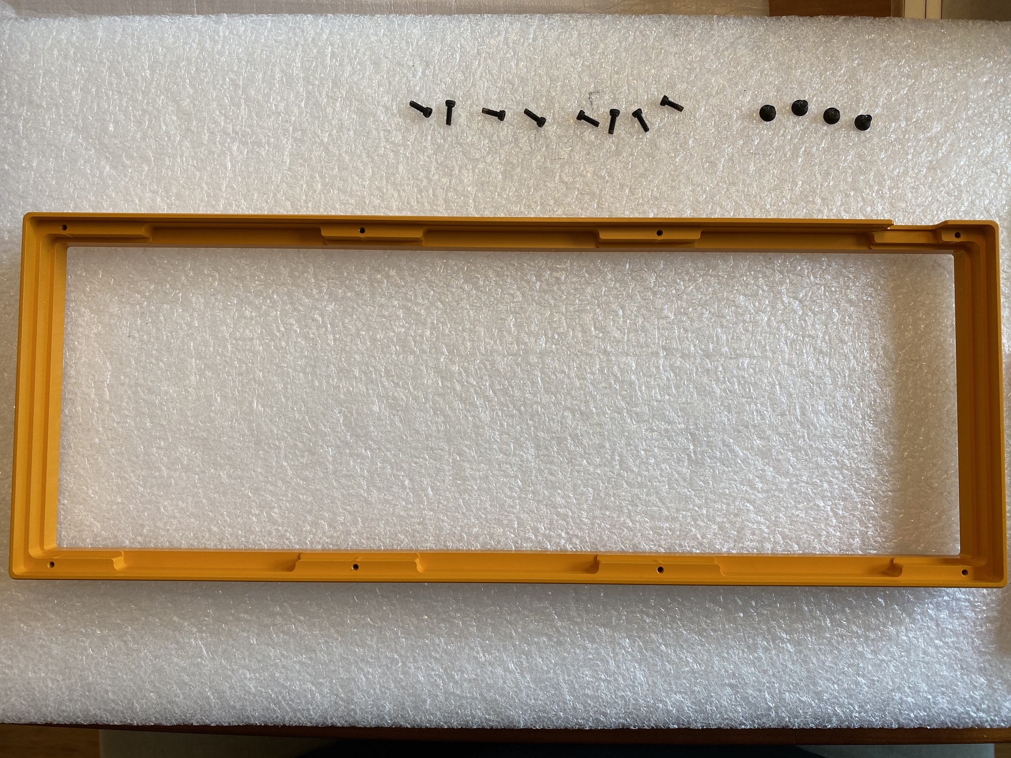
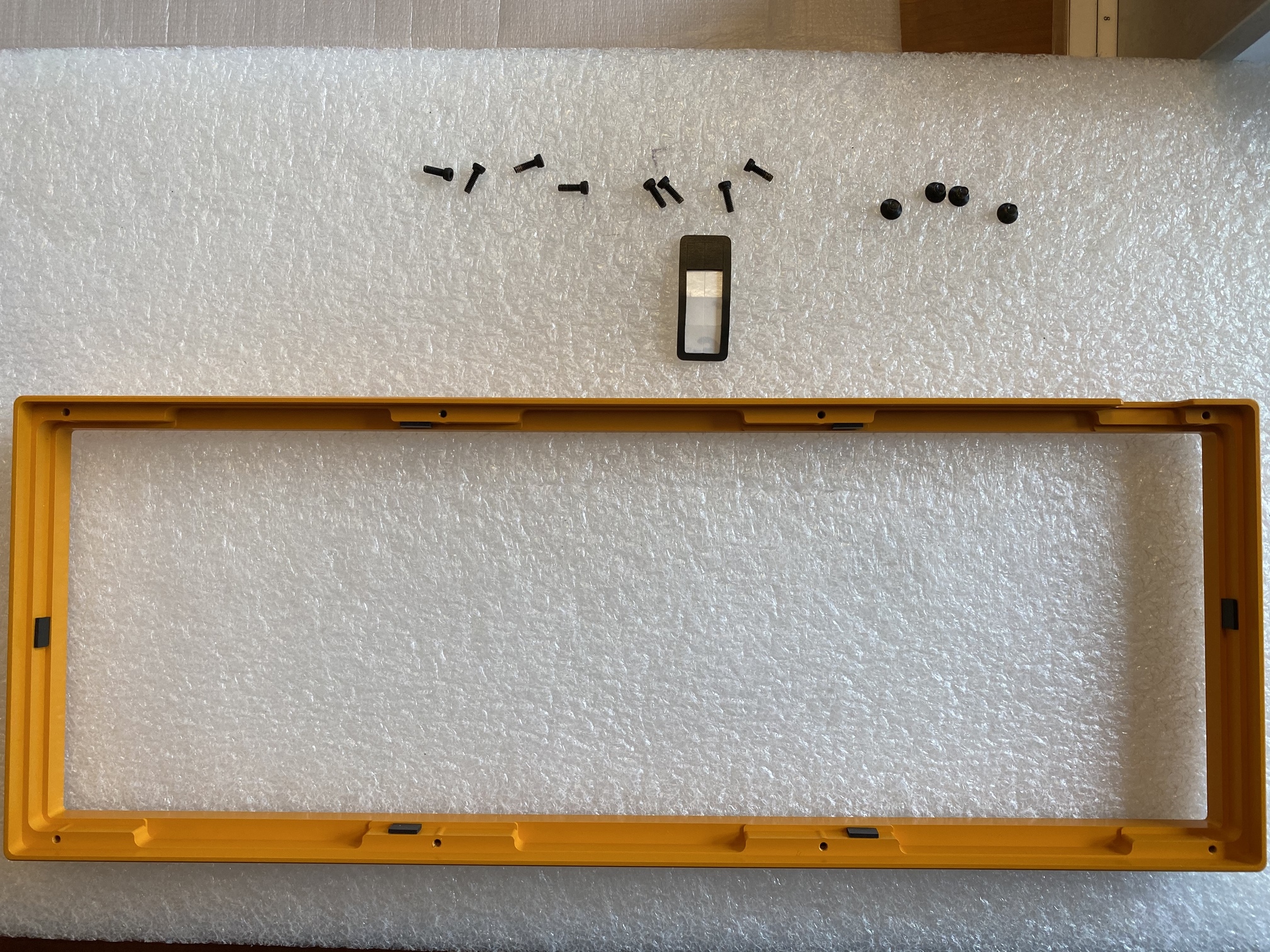
Finally, our first look at the Polaris housing. The e-yellow finish is very clean and even (ignore the spot to the lower right of the “S”, that’s something on my phone’s lens).
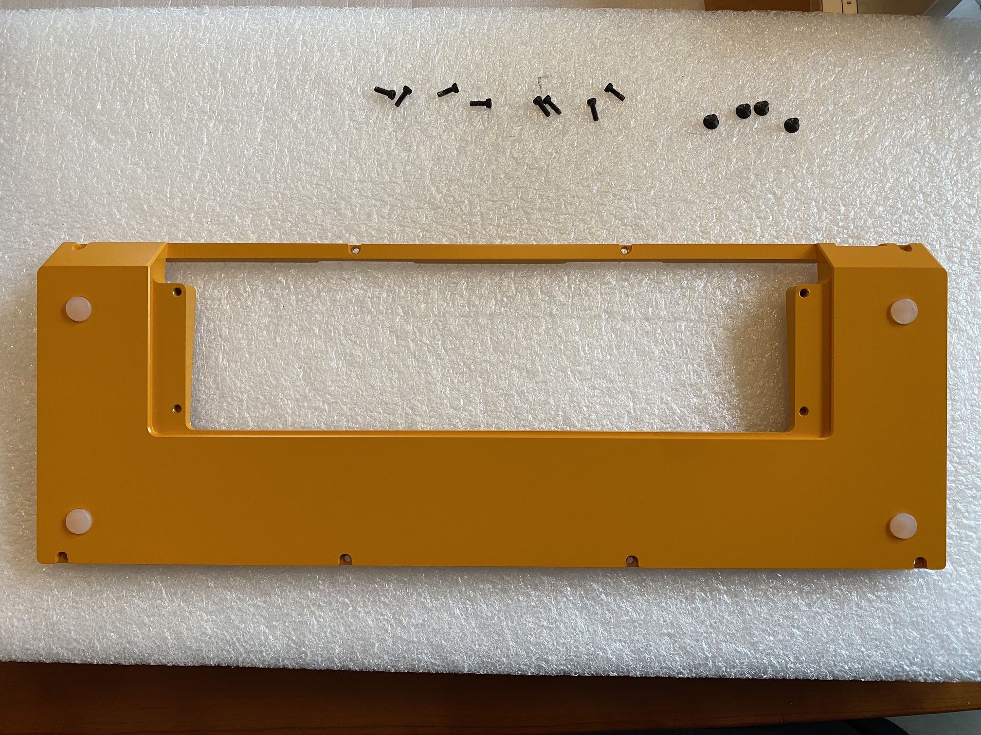
The underside is equally clean. It’s also worth noting the tolerances between the top and bottom case halves, as well as around the brass weight; the Polaris is punching above its weight in terms of machining and finish.
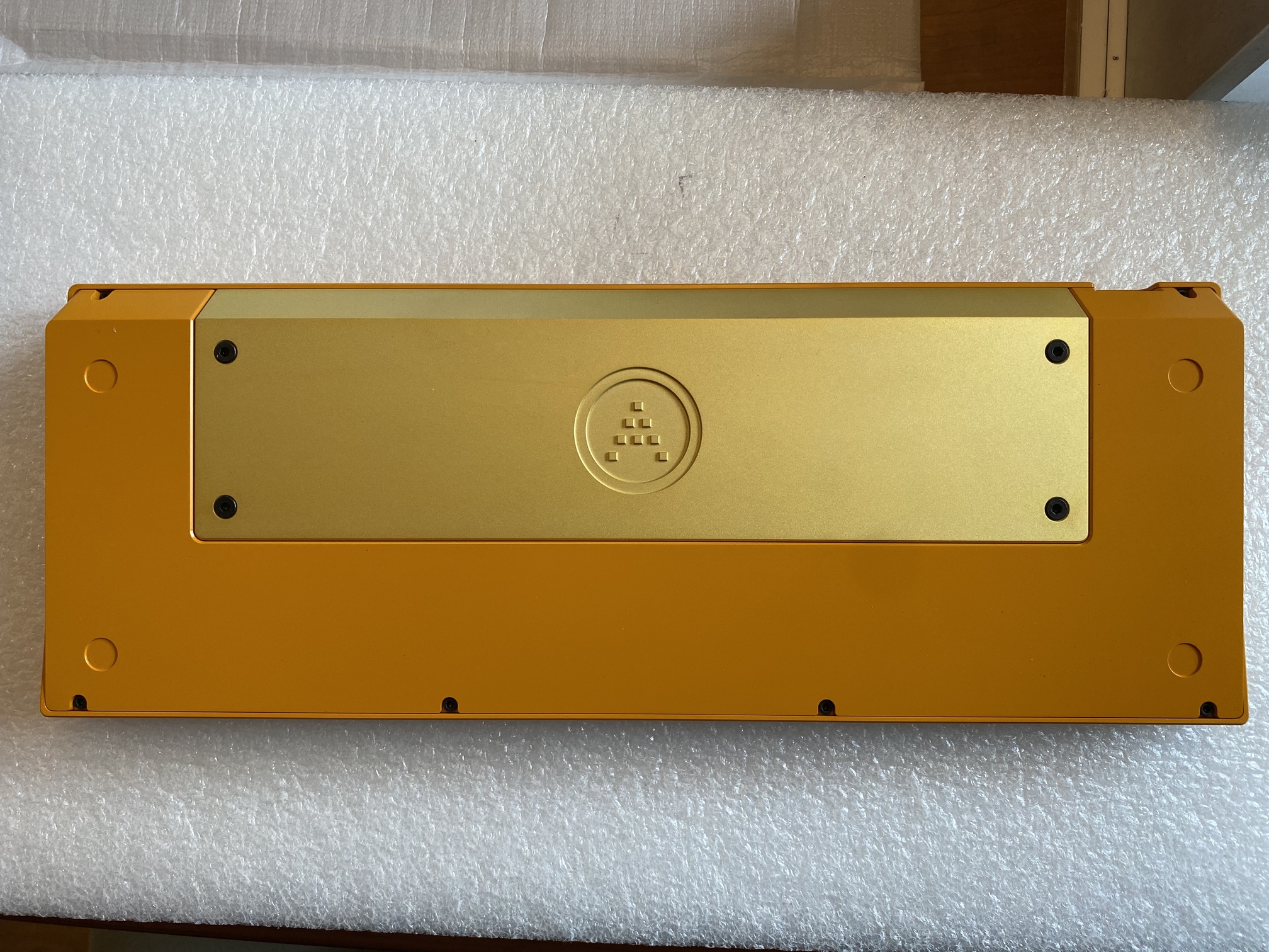
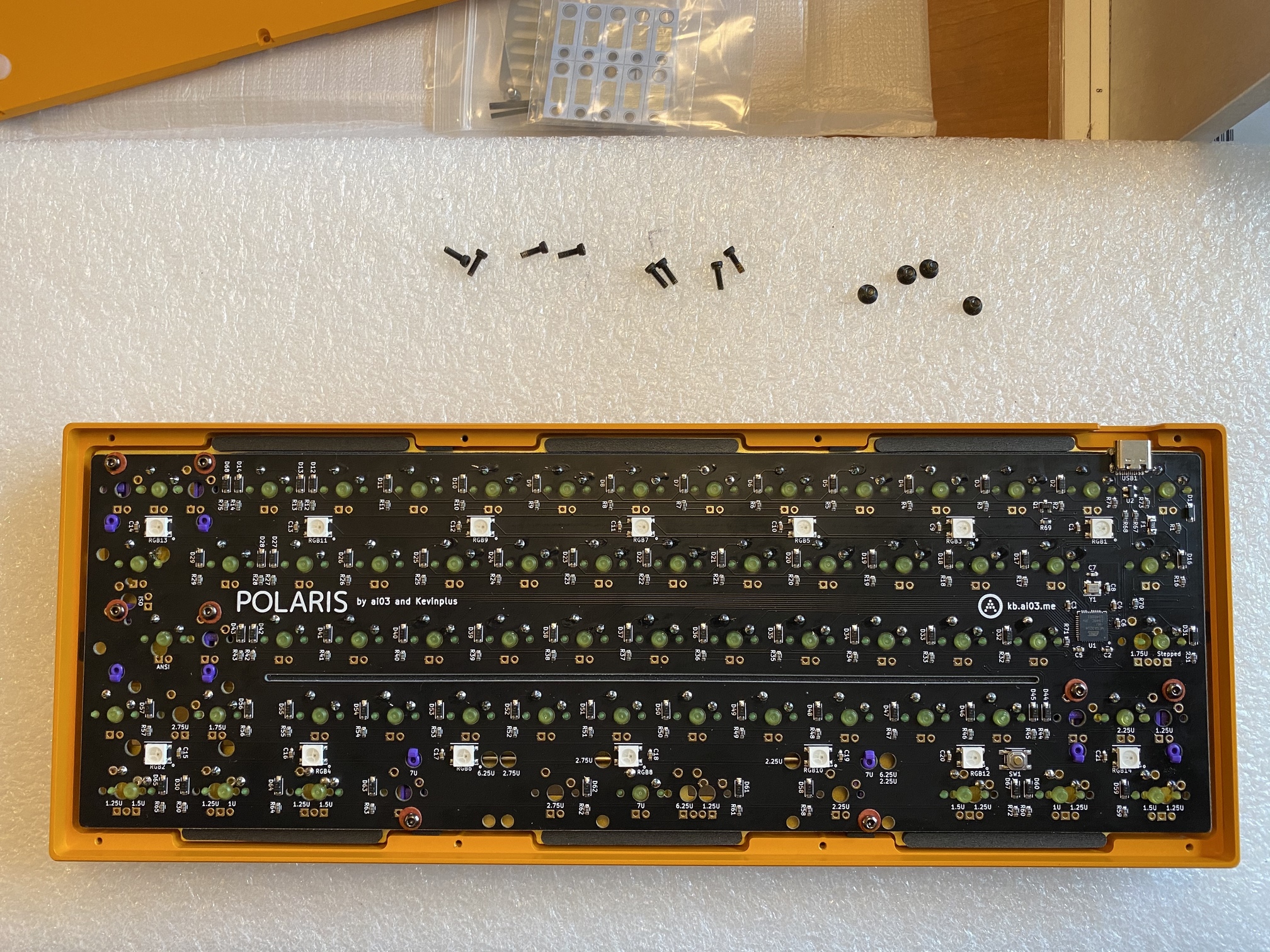
The brass weight has four screws which allow for easy removal.
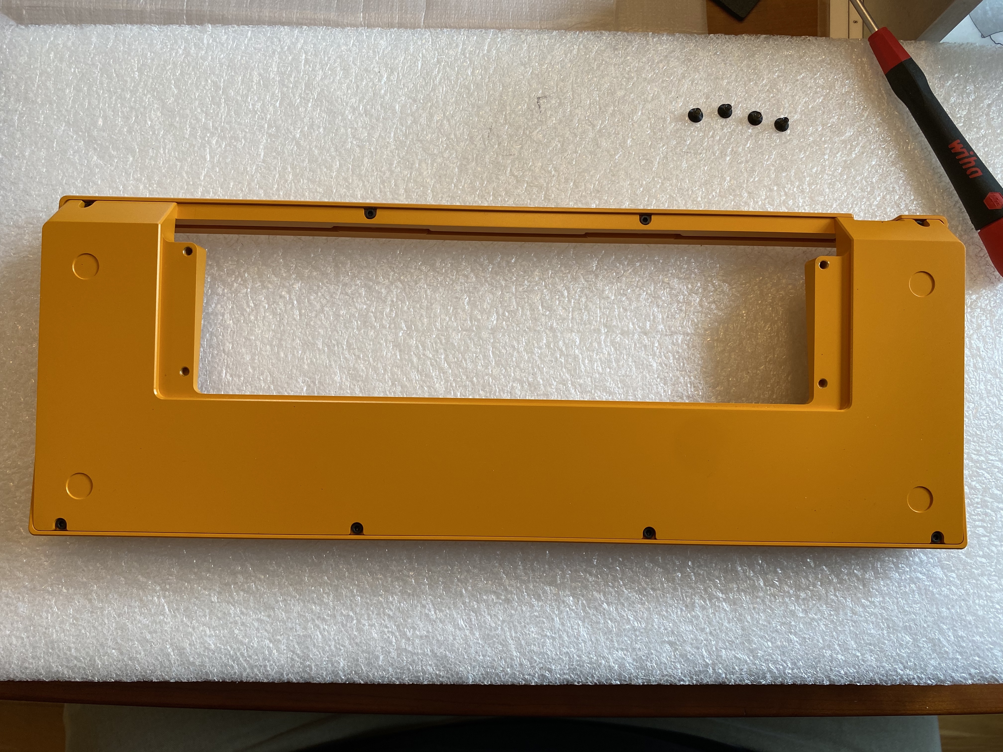
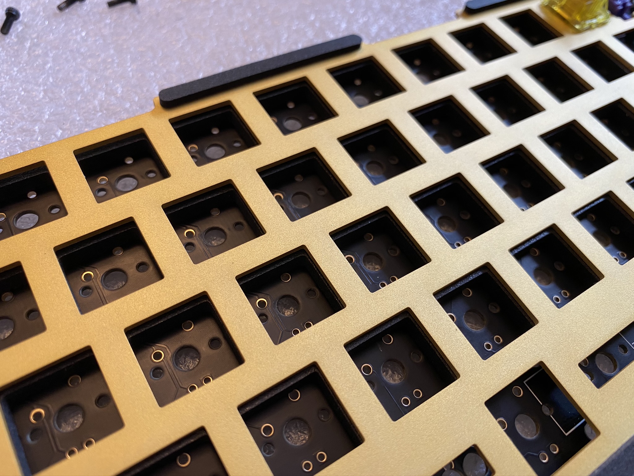
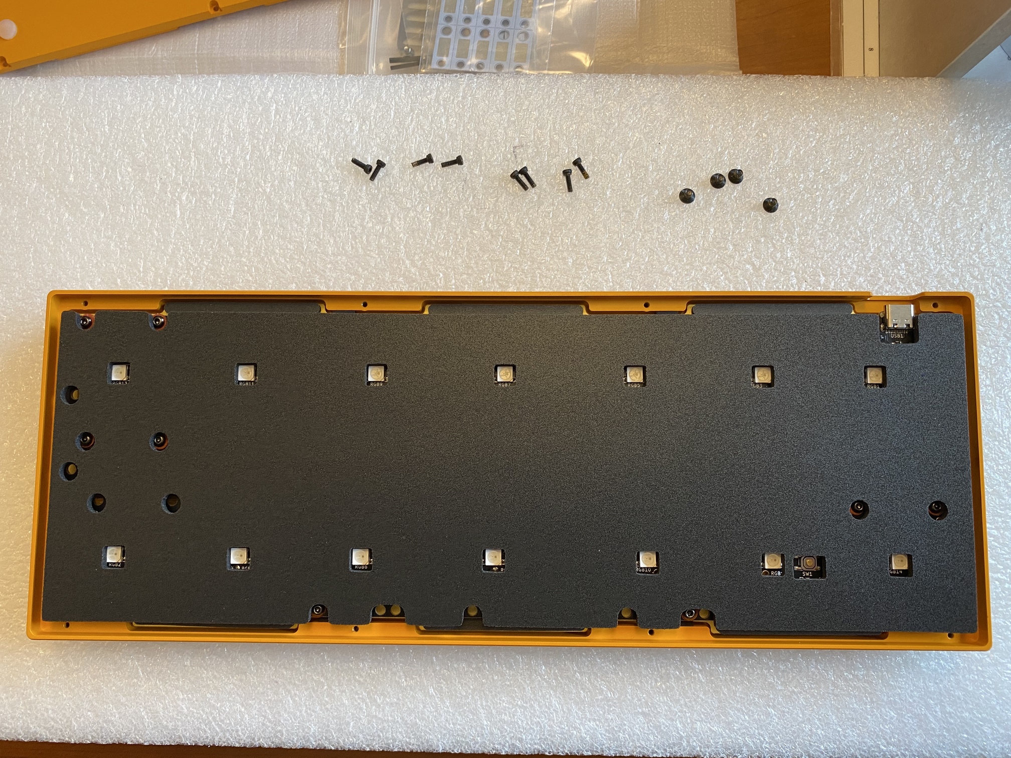
Eight more screws hold the top and bottom halves of the case together. Unscrewing those, we can see the underside of the top case, with six long cutouts for the plate tabs.
The Polaris is a gasket-mount board, and its implementation of gaskets involves adhesive foam strips, which are placed on both sides of each tab on the plate.
However, that’s not all. Two smaller gaskets are placed on either side of the middle interior wall of the case top…
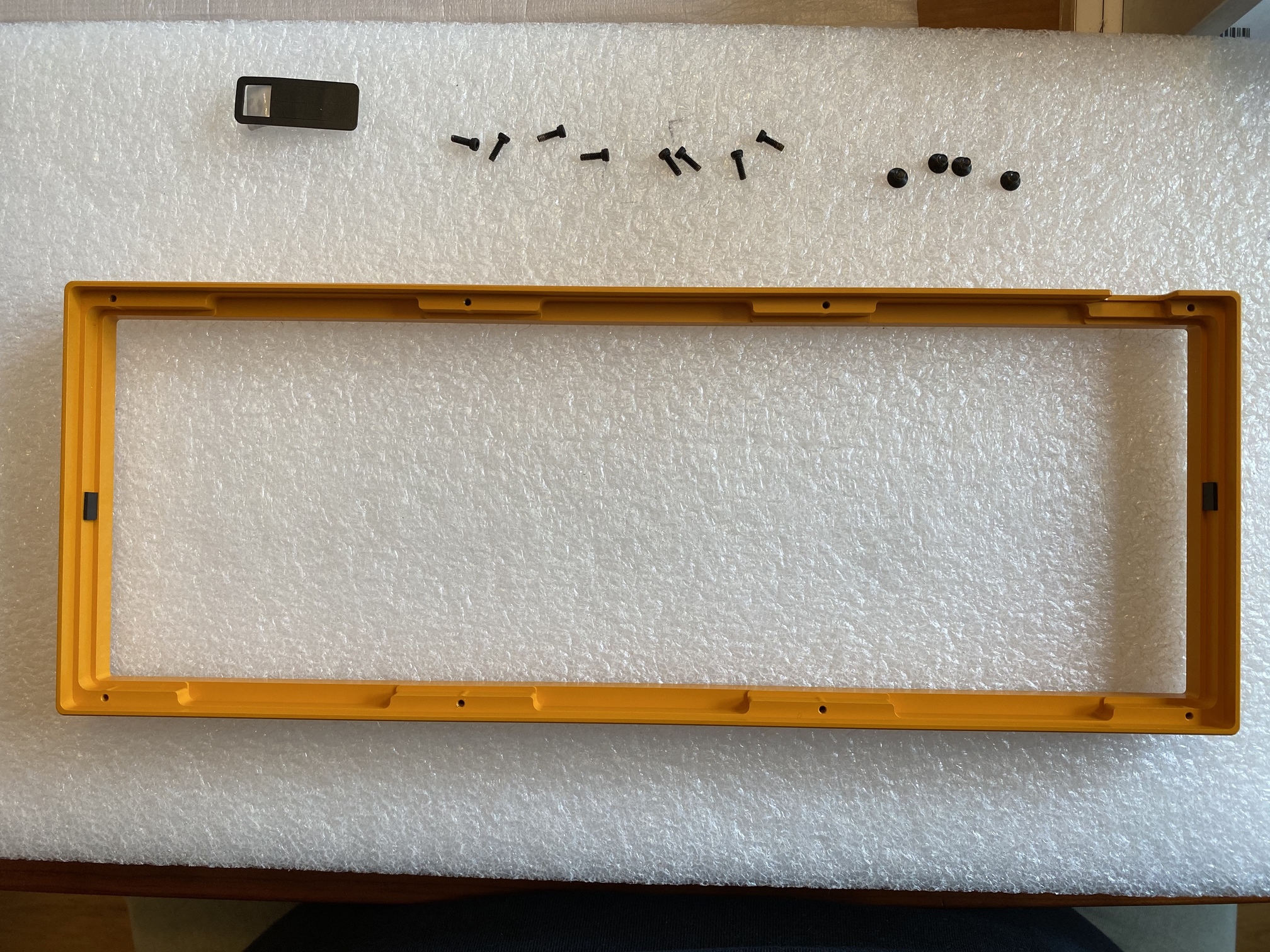
…as well as two more gaskets on the top and bottom interior walls flanking the tab cutouts.
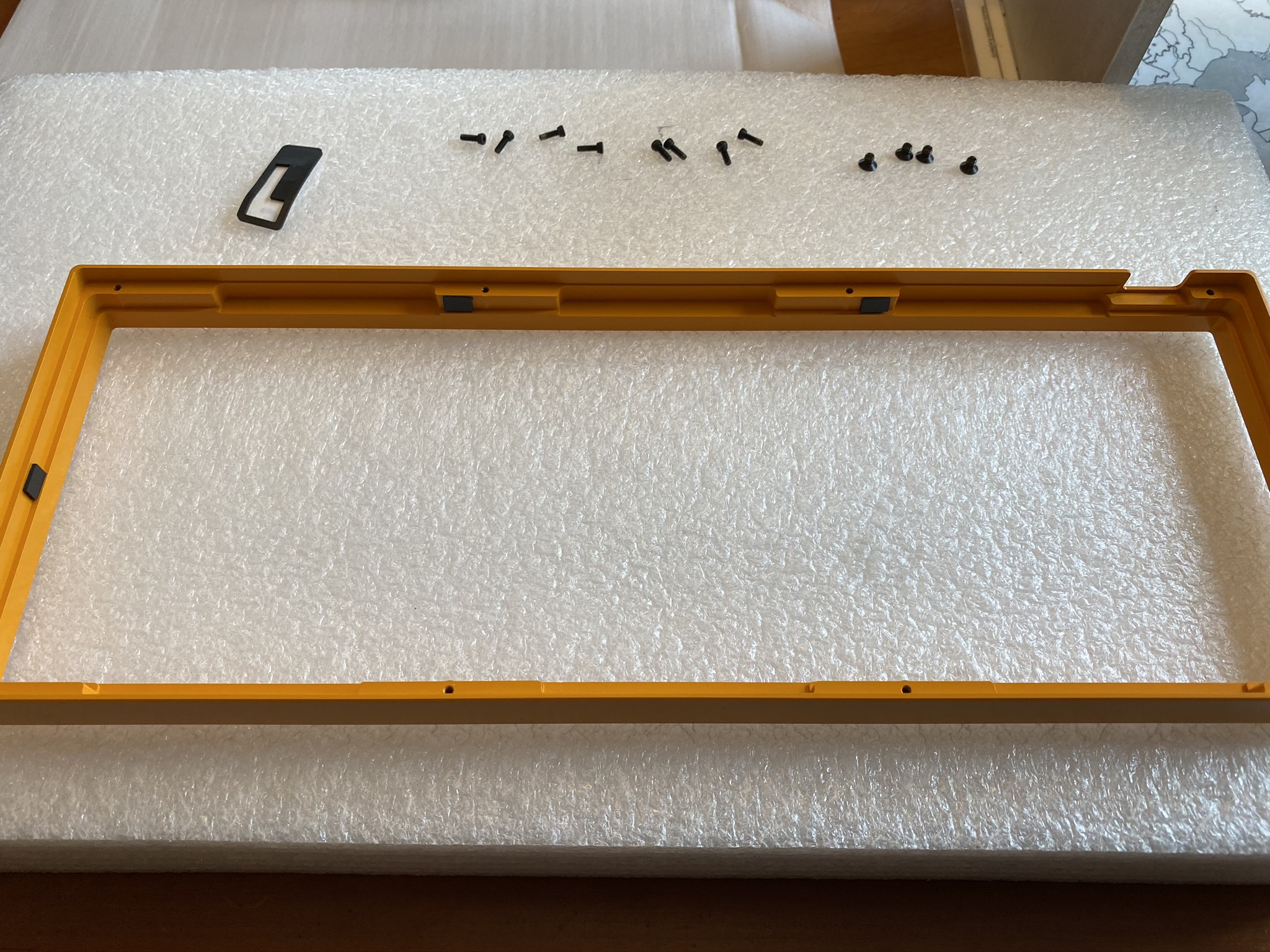
If you look closely, you can see all six case gaskets in the following photo.
While we’re playing with adhesive sheets, might as well install the case bumpons.
We’re done with adhesives, but we’re not done with foam. The Polaris includes an optional foam layer to be placed between the plate and PCB, which I opted to use to mitigate more of the brass clack. You can see the foam peeking out from underneath the plate’s switch cutouts, before I got it completely aligned. The foam had some elasticity to it, so I found it easiest to place a few switches at either end of the plate to help stretch it into alignment across the entire plate/PCB assembly.
From here, it’s the usual drill - mount the switches and check alignment before soldering.
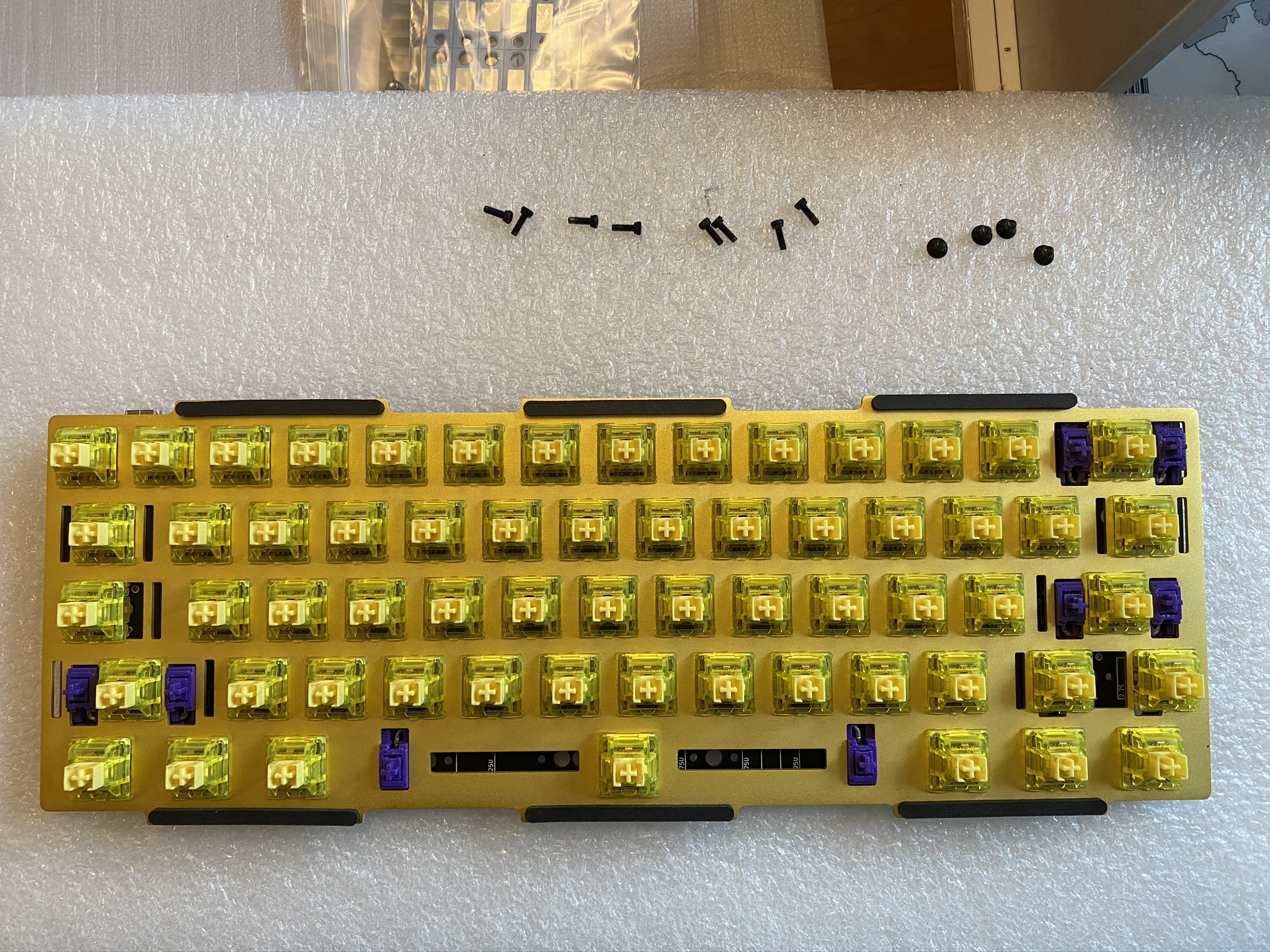
All soldered in.
Now comes the trickiest part of this build. The edges of the plate are meant to compress the case gaskets, effectively isolating the entire plate assembly from the rest of the case. However, since the gaskets are only held in place by adhesive, this means you have to carefully push the plate into place to make sure you don’t pull the gaskets away from the case. After trying to gently push the entire plate into place from directly above, I gave up on that approach because it looked as though it would be too easy to tear the gaskets off.
Instead, what worked was pushing the plate into the top of the case at angle, so that the two gaskets along the top were fully compressed, and then lowering the rest of the plate into place while still applying pressure to the top gaskets. Once that was done, I could relax the pressure, allowing the bottom gaskets to take more load. Again, if you look closely, you’ll be able to see all six case gaskets under compressive load from the plate.
We’re still not done with foam! One more layer is provided to eliminate the hollow space between the underside of the PCB and the case bottom. I appreciate the cutouts for the LEDs, reset switch, and stab screws.
From this point, all that remains is screwing the case components back together. One last look at all of those interior Laker colors - most likely they’ll never be seen again, but we’ll know they’re there.
Lessons learned
- Box-style switches acquired something of a bad reputation during the period when they were implicated in keycap cracking, and with Gateron Black Inks generally regarded as one of the top linears on the market, the Yellow Inks may have been overlooked (or not, since, like every other variety of Gat Ink, they are sold out at the moment). While there is a modestly different tone to the clack on these switches, they feel and sound nice. I’d be curious to see how they sound with a (very, very light) coat of 205g0.
- All that foam and those gaskets make a substantial difference in sound. This board has some of that “light raindrops on windowpane” sound I personally enjoy. Had this been my own board, I might have experimented with leaving the PCB/plate and PCB/case foams out, just to see how much clack is left when only the gaskets remain. (turning around, to look at my own personal Polaris kit on a shelf, looking back at me with sad puppy eyes - soon™)
- ai03 and kevinplus killed it on QC and packaging for this group buy. I don’t know the final Polaris numbers, but it was an unlimited buy, and rumor has it hundreds were manufactured. If this kit was typical, then they did an amazing job, particularly while a pandemic was underway. Special mention: a nice, thorough build guide, something we rarely see with custom builds.
Tipoff time.
Specifications
case: Polaris
- e-yellow case
- clear matte PVD brass weight
case dampening:
- precut foam w/ kit
- 12 adhesive foam gaskets for plate
- 6 adhesive foam gaskets for case
PCB: Polaris
plate: Tsangan 60% brass full plate
plate/PCB dampening: precut foam w/ kit
stabilizers: C3 screw-in
- purple, 1x7u, 3x2u
stabilizer mods:
- lubed with SuperLube
- installed with cloth washers
switches: 61x Gateron Yellow Inks
switch mods:
- springs tub-lubed with Krytox GPL 104
- stems hand-lubed with Tribosys 3203
- no housing lube
keycaps: GMK Violet on Cream
HxWxD (without caps or feet): 1.13" x 11.63" x 4.31"
HxWxD (without caps): 1.19" x 11.63" x 4.31"
HxWxD: 1.44" x 11.63" x 4.31"
assembled weight: 1.695 kg (3.74 lb)
10 Likes
Great build log. I had trouble with gaskets too. More so because I forgot to take the keycaps off after putting them on to check keycap alignment. This left PCB sitting too high when upside-down so I had to hold the case top between my legs while placing the PCB between side gaskets.
It was only after I finished assembling that I remembered I had built a custom rig for holding keyboard upside while working with Topre domes. Doh.
2 Likes
Nice looking build. I enjoyed the write up. I like my Gateron yellow inks, but I wish they weren’t a “speed” switch that actuated so high up. However, their smoothness, sound, and spring weight are very appealing to me.
3 Likes
As usual, very nice report
2 Likes
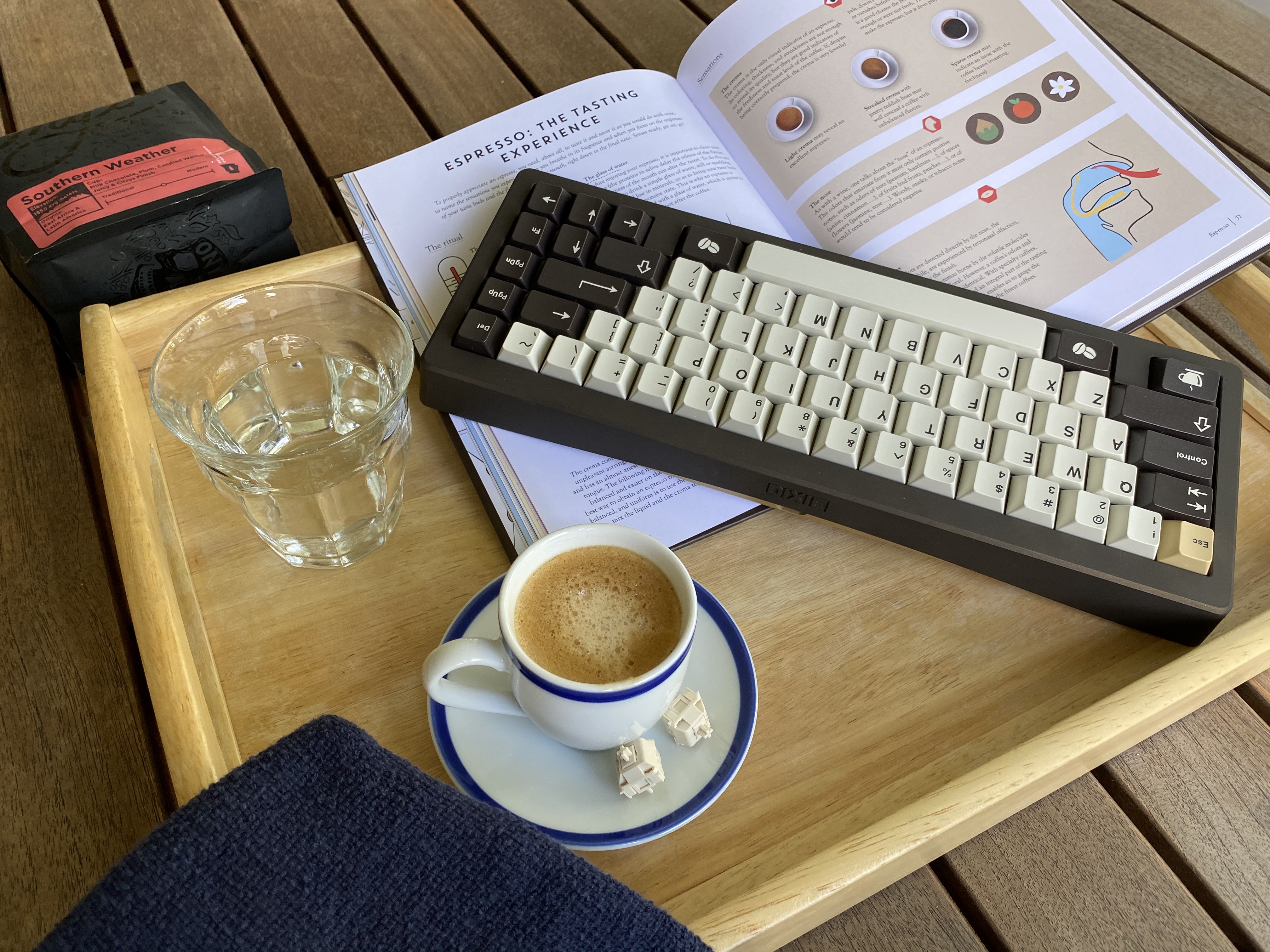
Build #39: Kaffeeb(r)auer
How many of us begin our days at a keyboard with a cup of coffee? Let’s take that relationship to the next level.
I’ve written before about the dangers of trying to color match boards and keycap sets based on renders, or even photos - color matching is no joke. But as much as I try to be rational and scientific about these things, sometimes I just have a hunch. When I saw the bronze cerakoted Bauer and GMK Café, I knew what had to happen - and, as awful as my FCFS/raffle/RNG mojo has been in recent months, I got lucky here with the Bauer. Let’s start brewing.
Grind
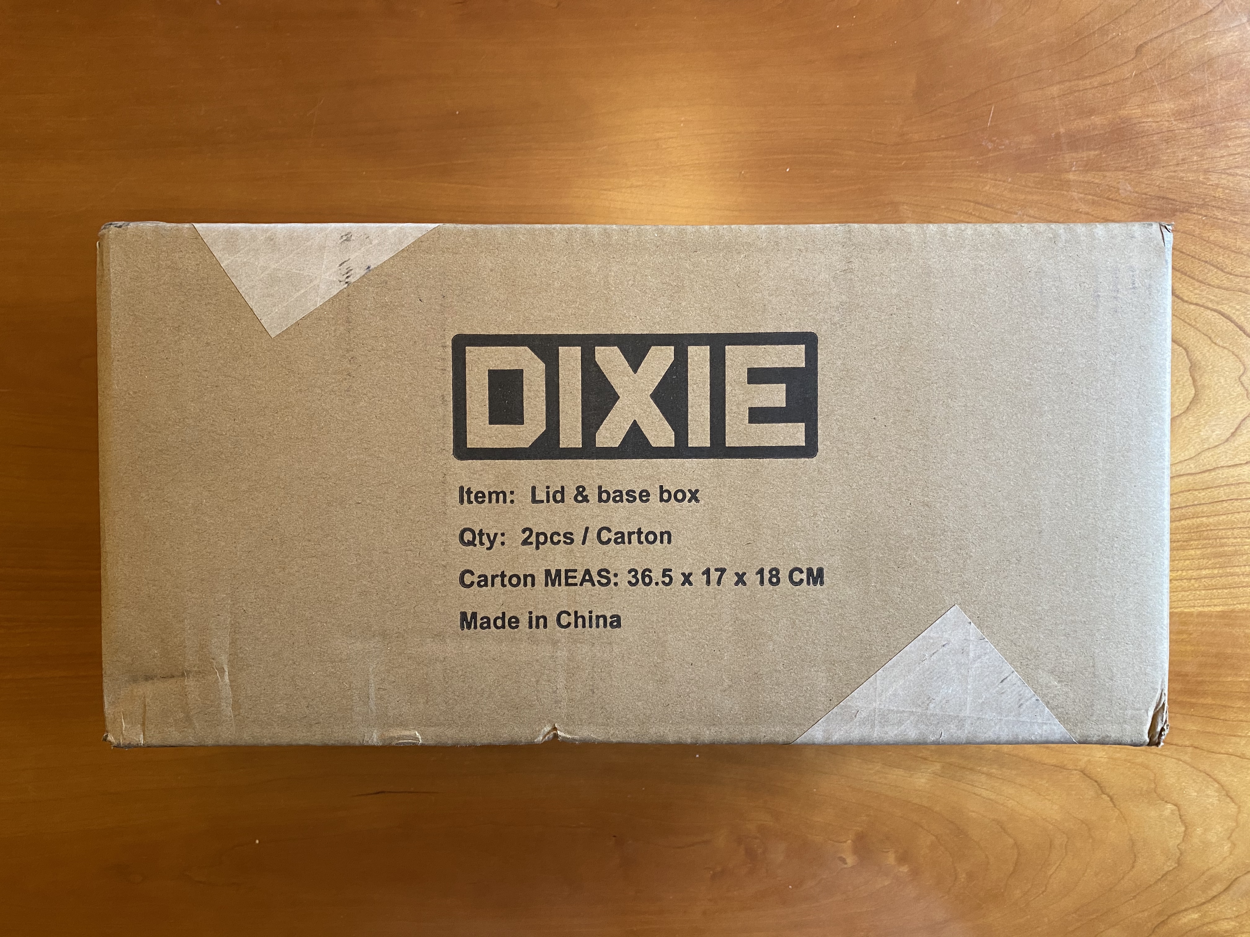
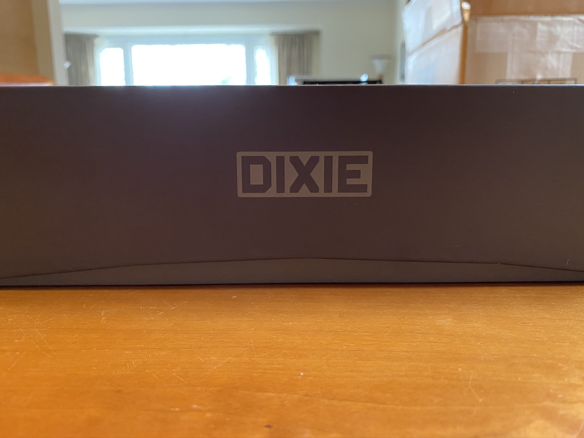
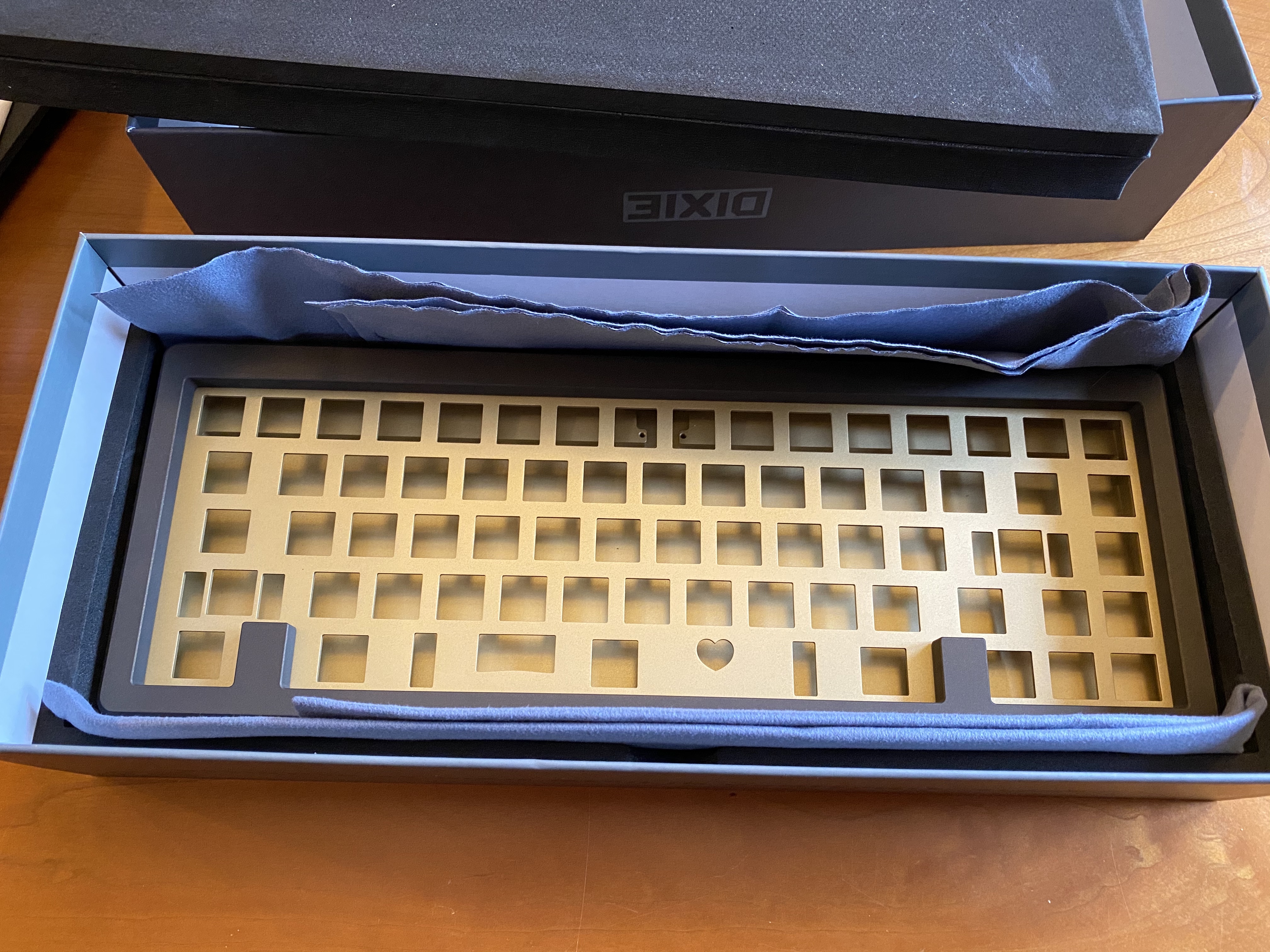
This is what showed up on my doorstep back in March 2020. Are we excited yet?
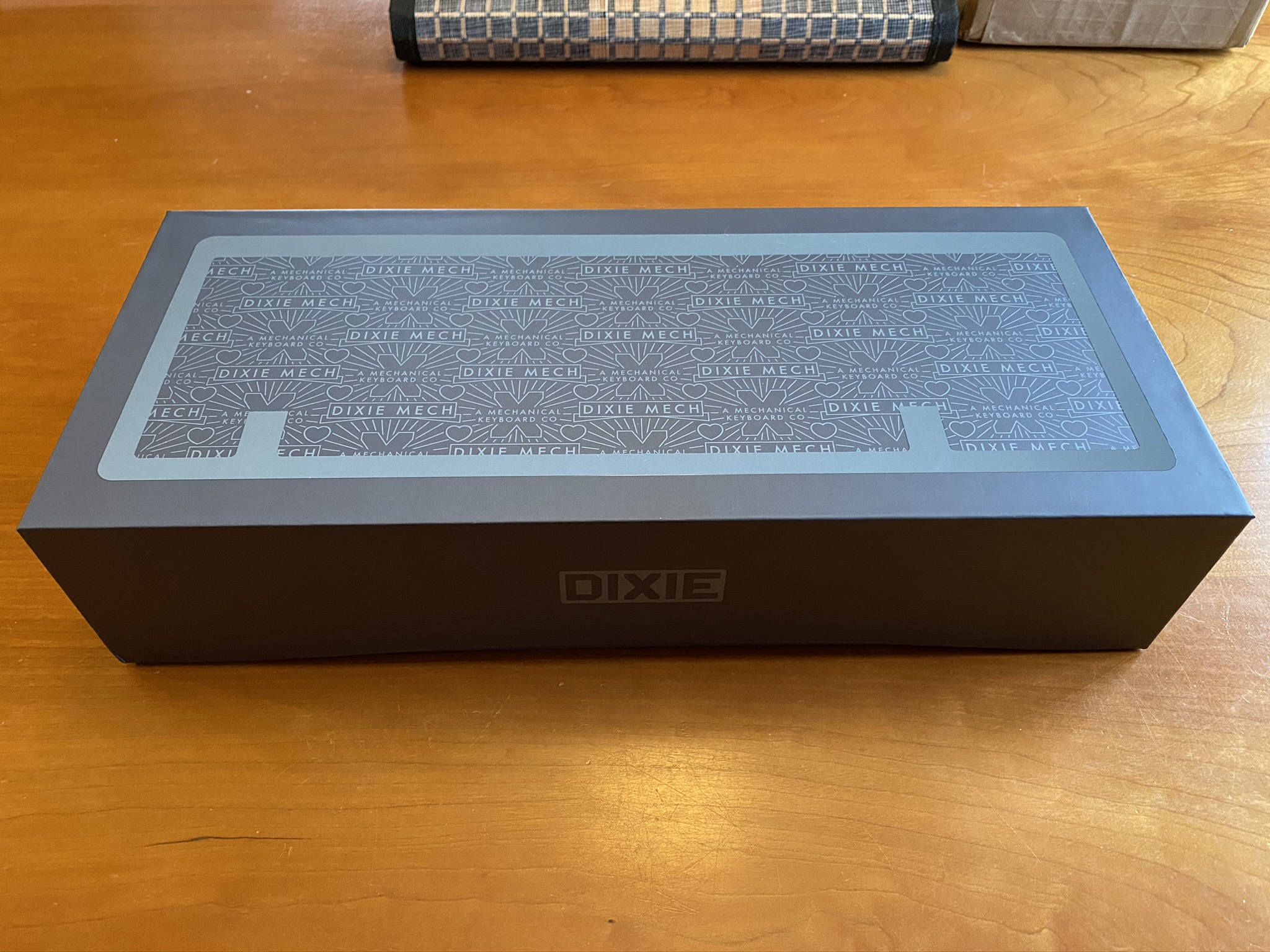
There is a part of me that doesn’t care all that much about the packaging details - ultimately, it’s the product that counts. Then there’s the other part of me that gets fired up when I see touches like this echo of the Bauer curve on the packaging. Details matter!
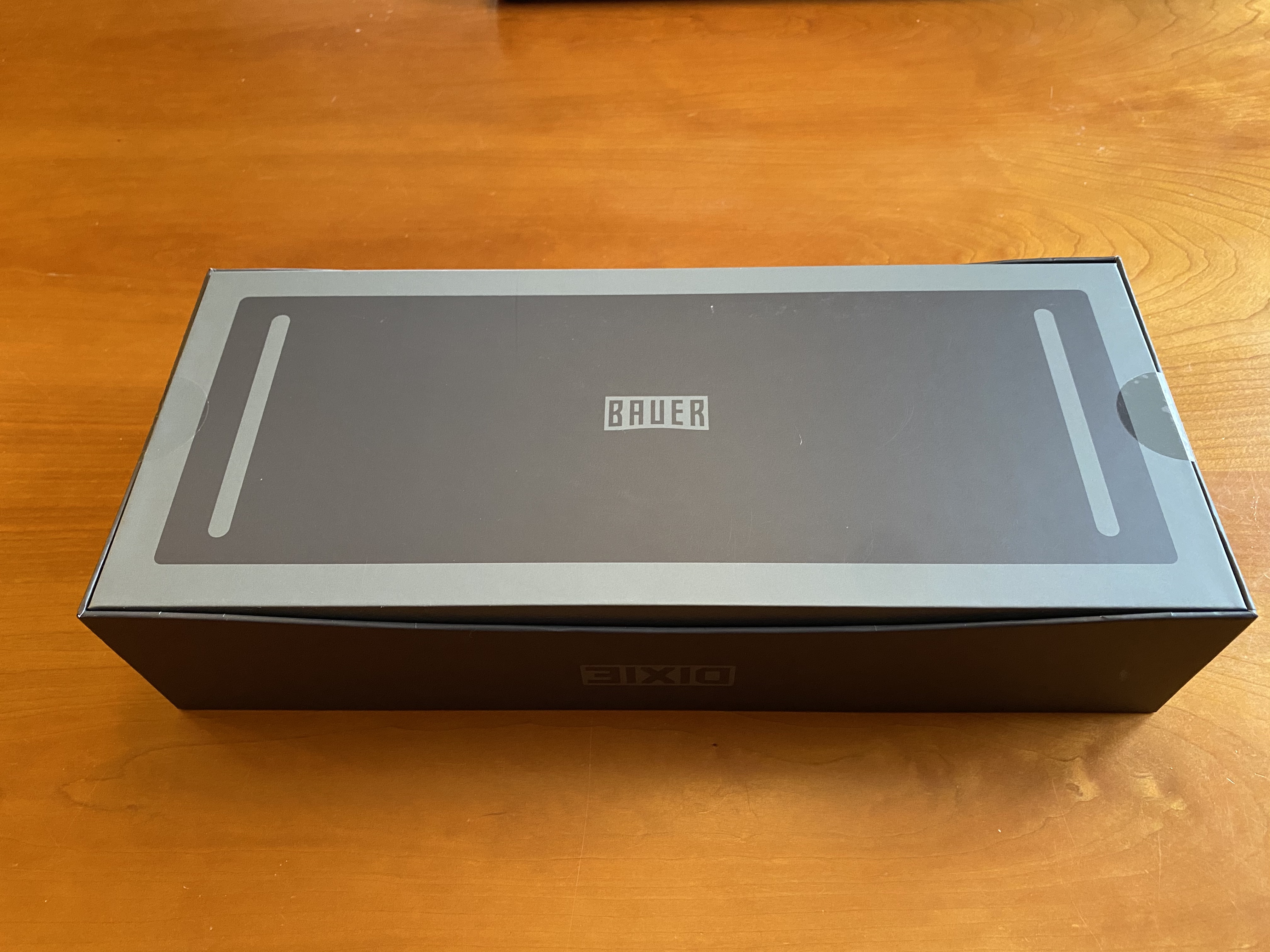
And again - echoing the Bauer base, with virtual bumpons.
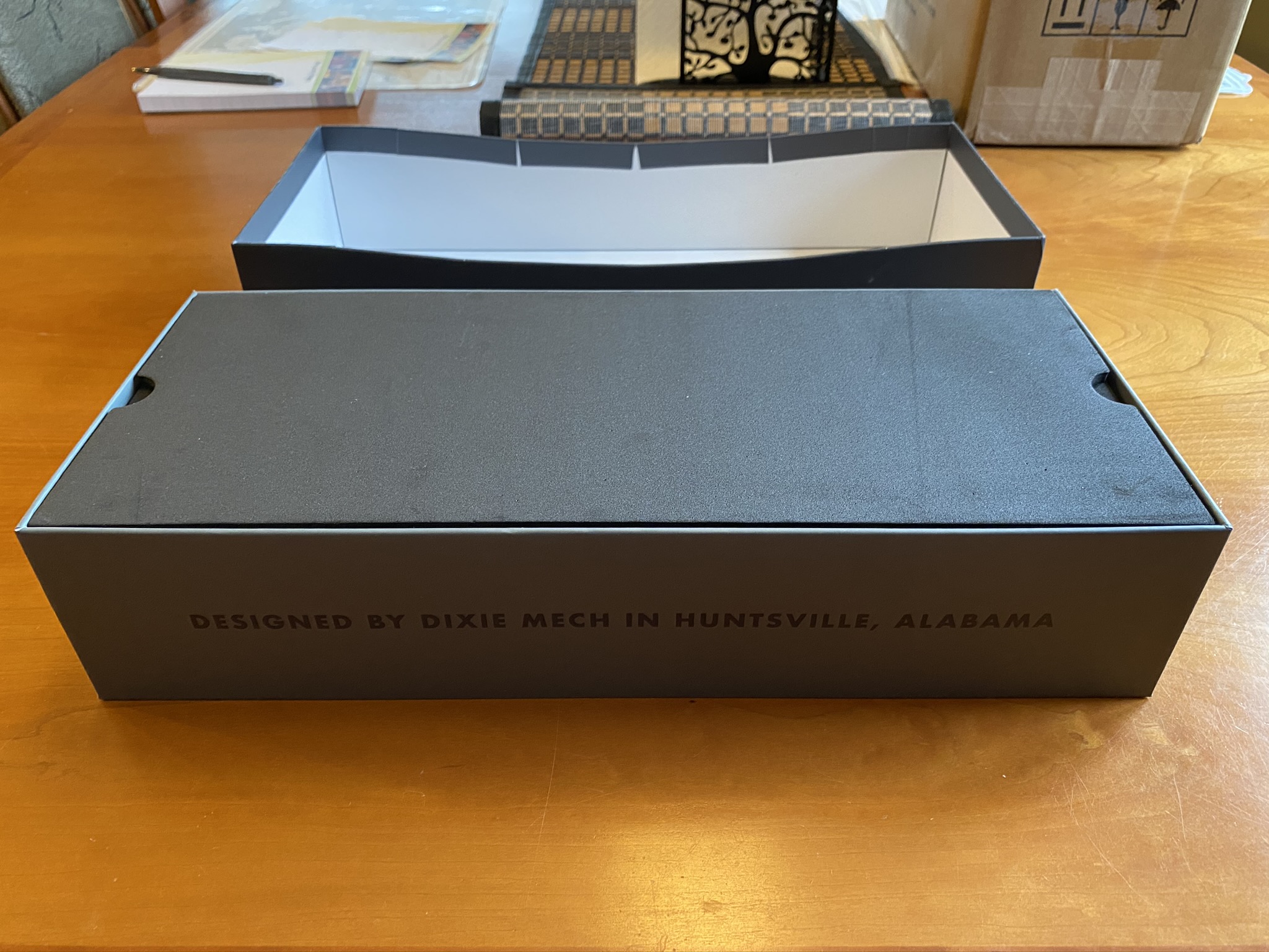
Yes, it’s a slow reveal. Finger holes for the protective foam - another minor detail, but I like it.
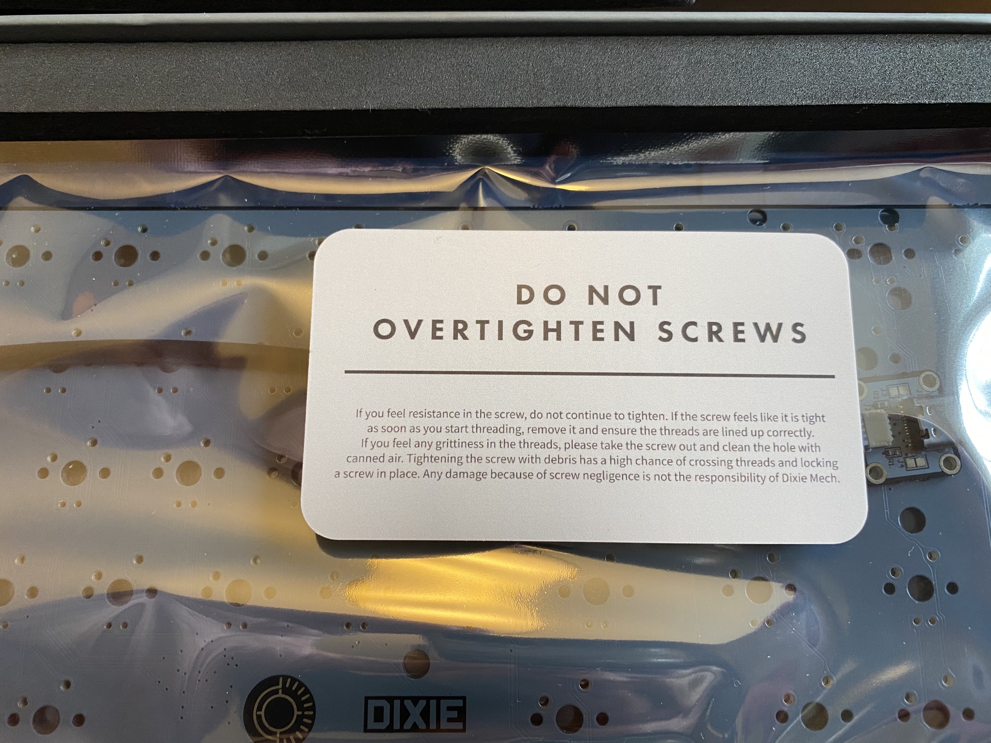
We’ll get to the PCB in a moment, but this is a nice touch, printed on good cardstock. Thanks, Mr. and Mrs. Dixie!
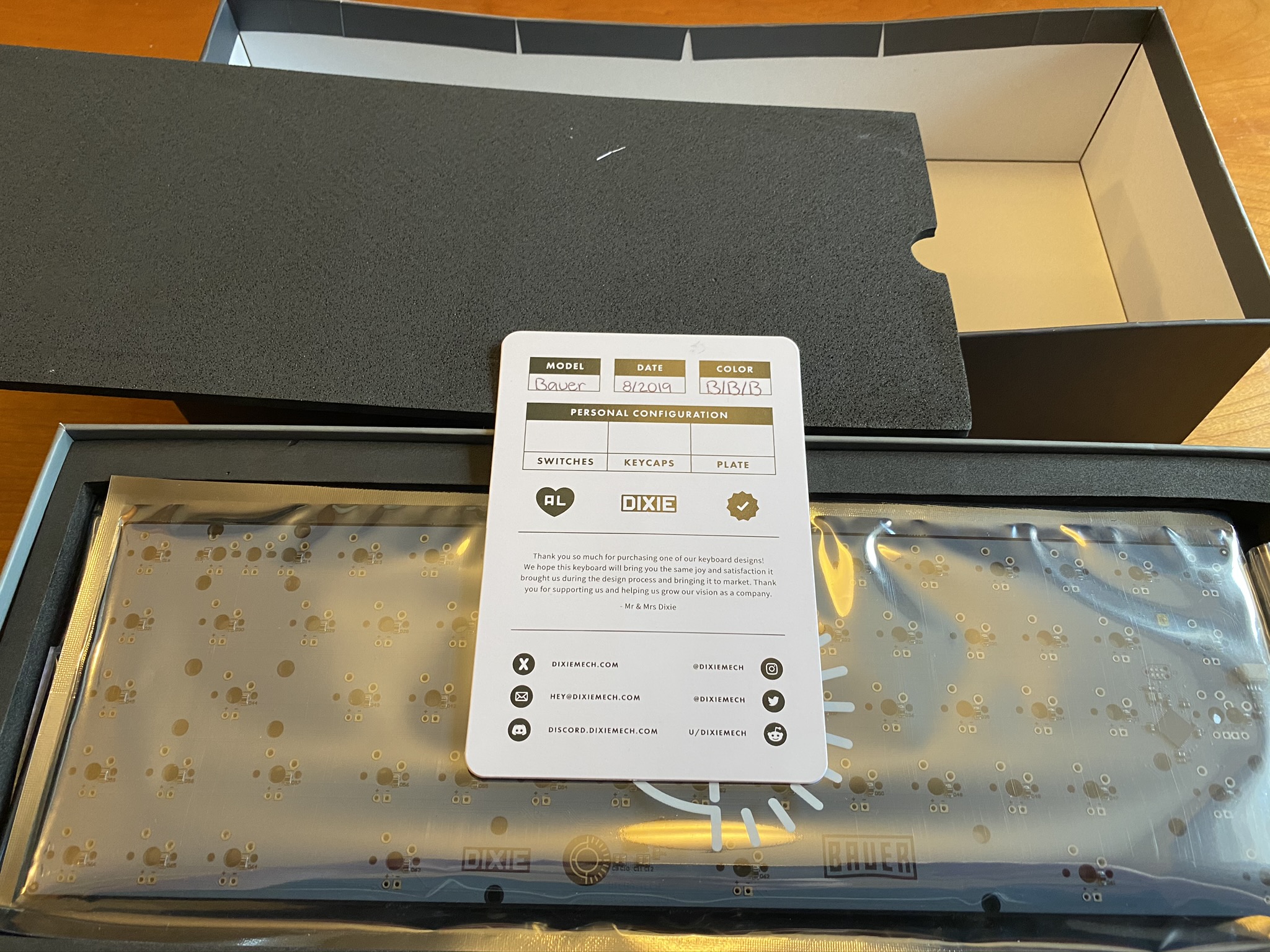
And, a helpful cautionary warning. Sadly, grit in the threads is a problem I’ve encountered the hard way on a somewhat recent build, so this is both topical and useful.
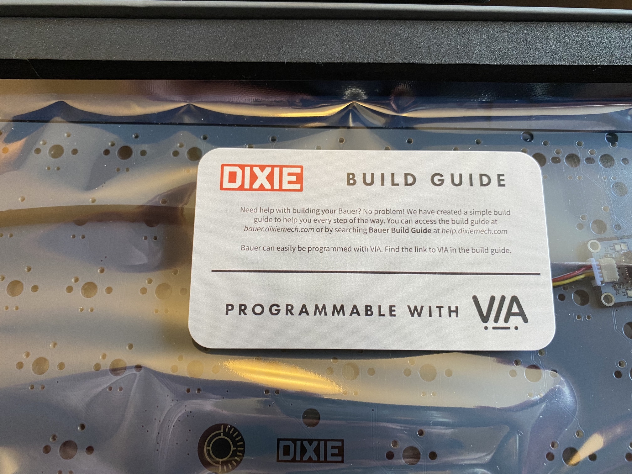
I don’t want to spoil the Bauer’s thunder, nor my own with this build log, but take a moment to check out the Bauer build guide. It sits right next to the Norbaforce cartoon guide at the top of the heap, as far as instruction manuals for custom keyboard builds go.
Tamp
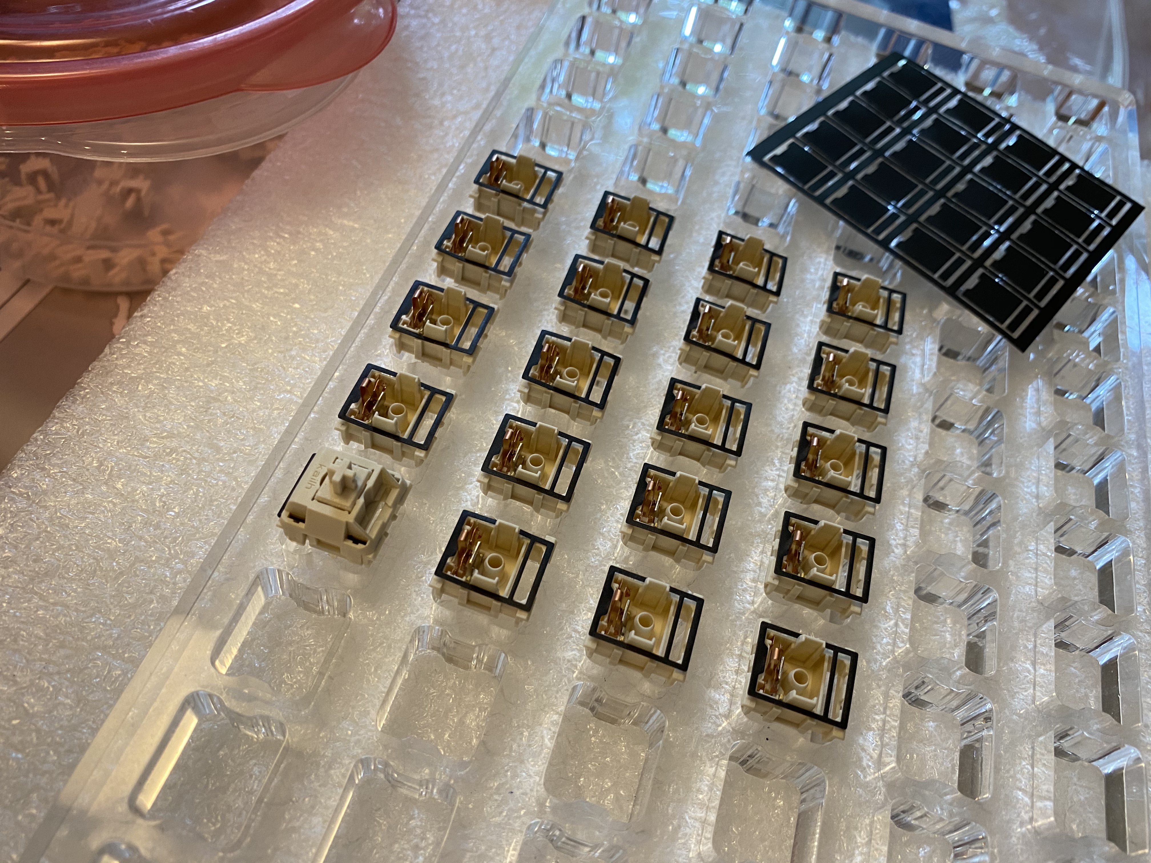
I know, I’m such a tease. But before we go further, let’s get switch tuning out of the way. For this build, I wanted to try out the Deskeys switch films. These come in precut sheets, and individual films can just be peeled away from the backing. They’re not particularly sticky, but they do crease easily, so some care is warranted.
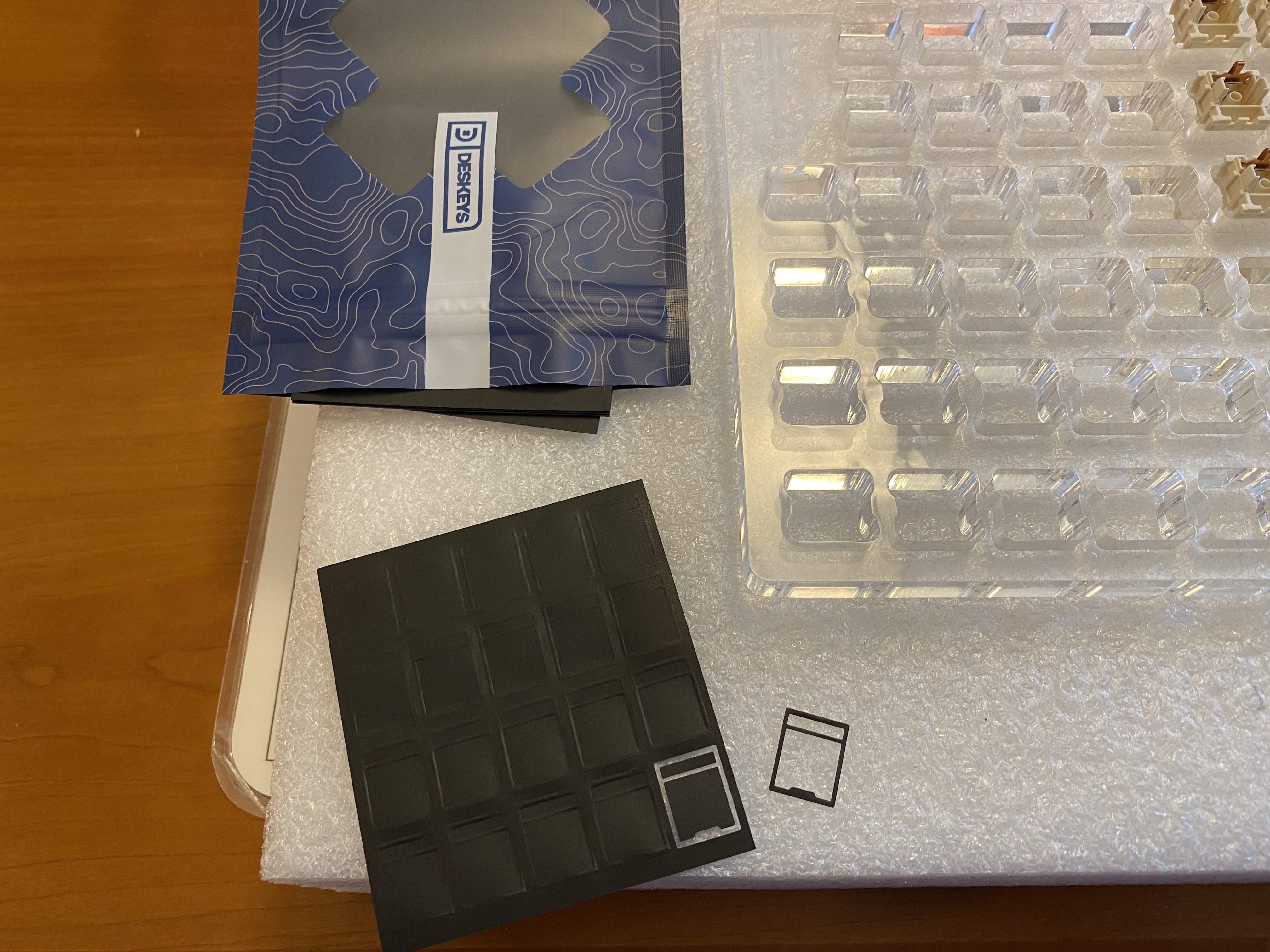
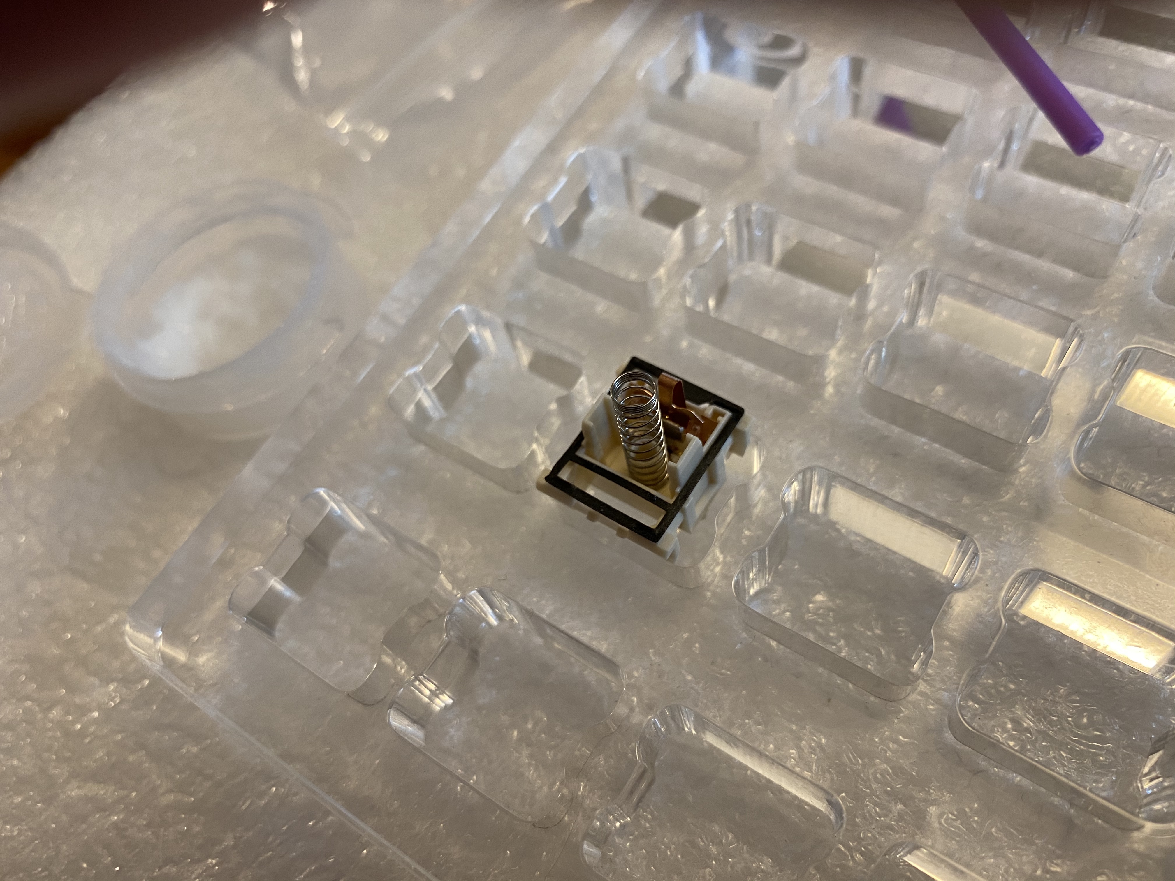
A disassembled NovelKeys cream, with tub-lubed spring and film in place.
When I’m lubing and modding switches, I prefer to work in small batches; I don’t always have time to do an entire board in one sitting - and if I’m being honest, the breaks are necessary to keep me from losing my mind. It is my fervent hope that good factory-lubed switches become a thing, but until that time…
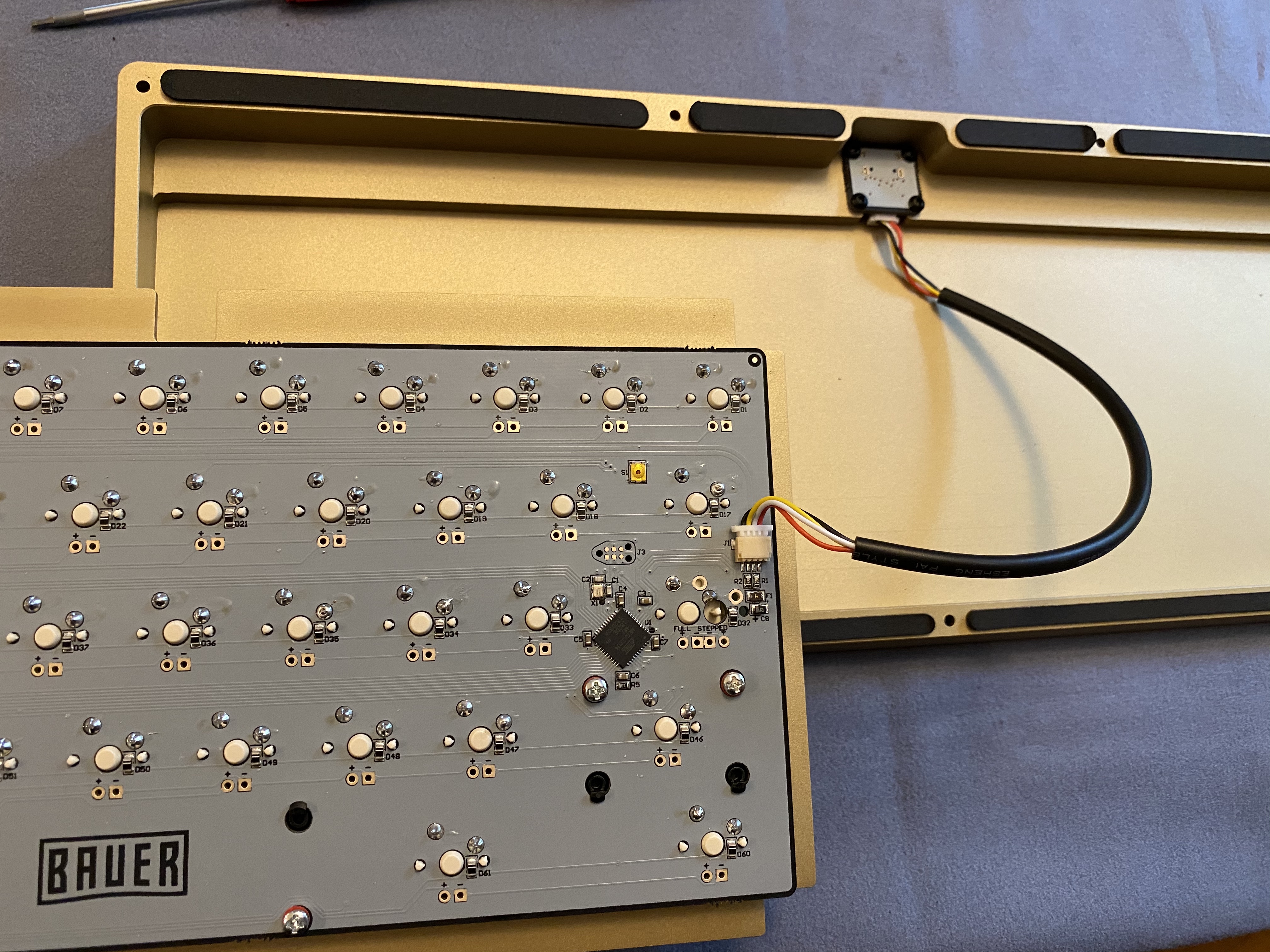
Let’s take a look at the PCB. The Bauer’s PCB is the WT65-B, a Wilba production, so we know what to expect - clean traces and design, and a beautiful solder mask. Branding is kept to a tasteful minimum.
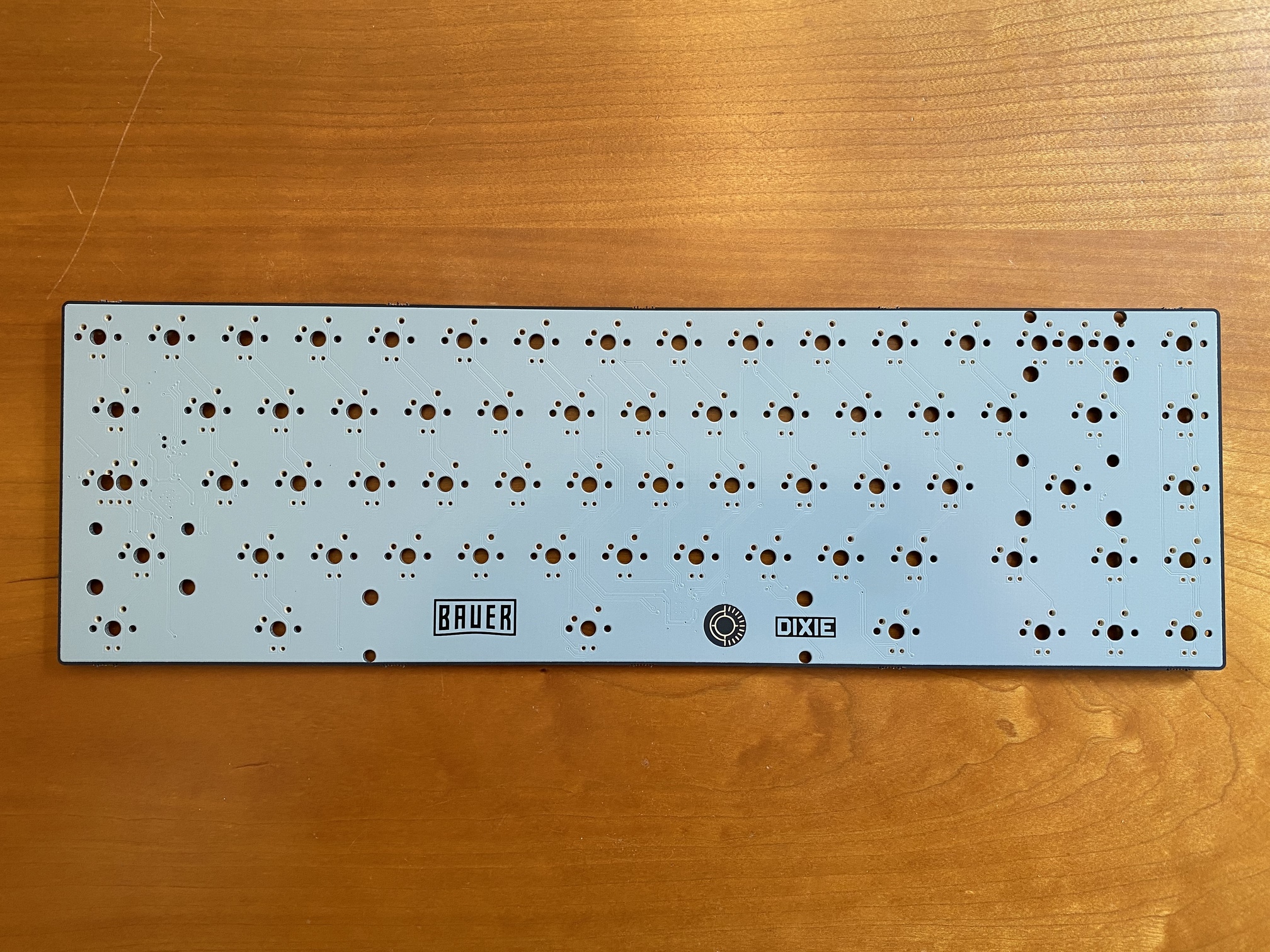
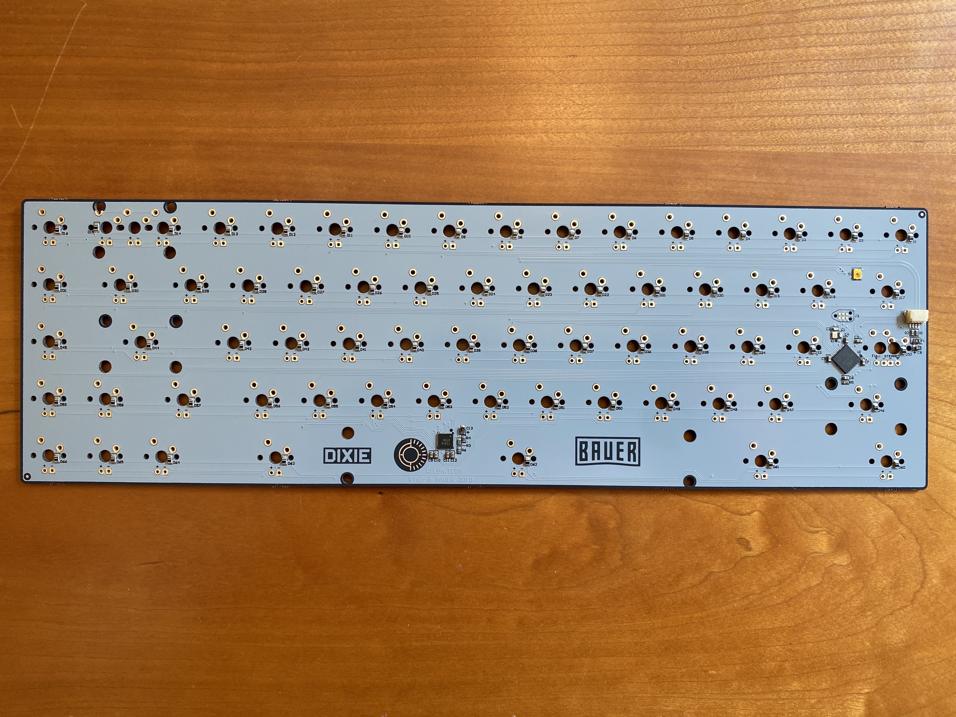
The underside is similarly clean. One notable addition is the JST daughterboard connector, over on the right side of the PCB near the Atmega32U4 controller chip. If I have any complaint here, it’s the lack of key labeling for each switch cutout. But this is just nitpicking, since this is almost the exact opposite of a “Swiss cheese” PCB - there are very few alternate layout options for the Bauer PCB, and it’s pretty obvious what those options are.
And, using the stock plate that comes with the Bauer kit (in this case, a sandblasted brass plate), even those few choices are eliminated.
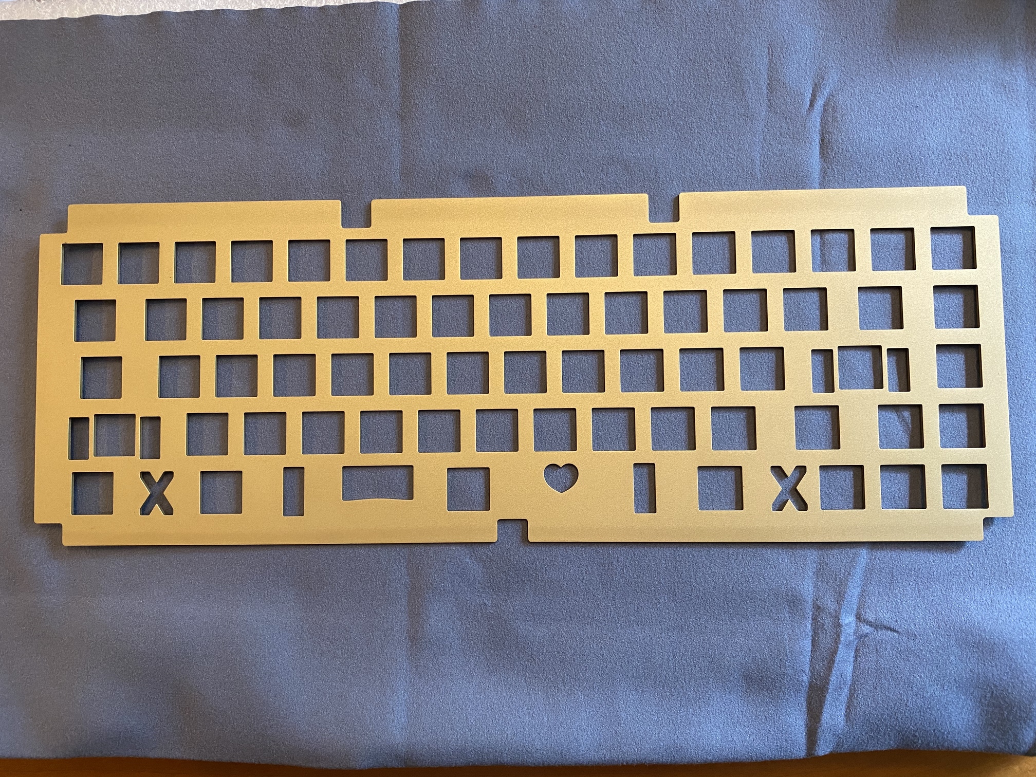
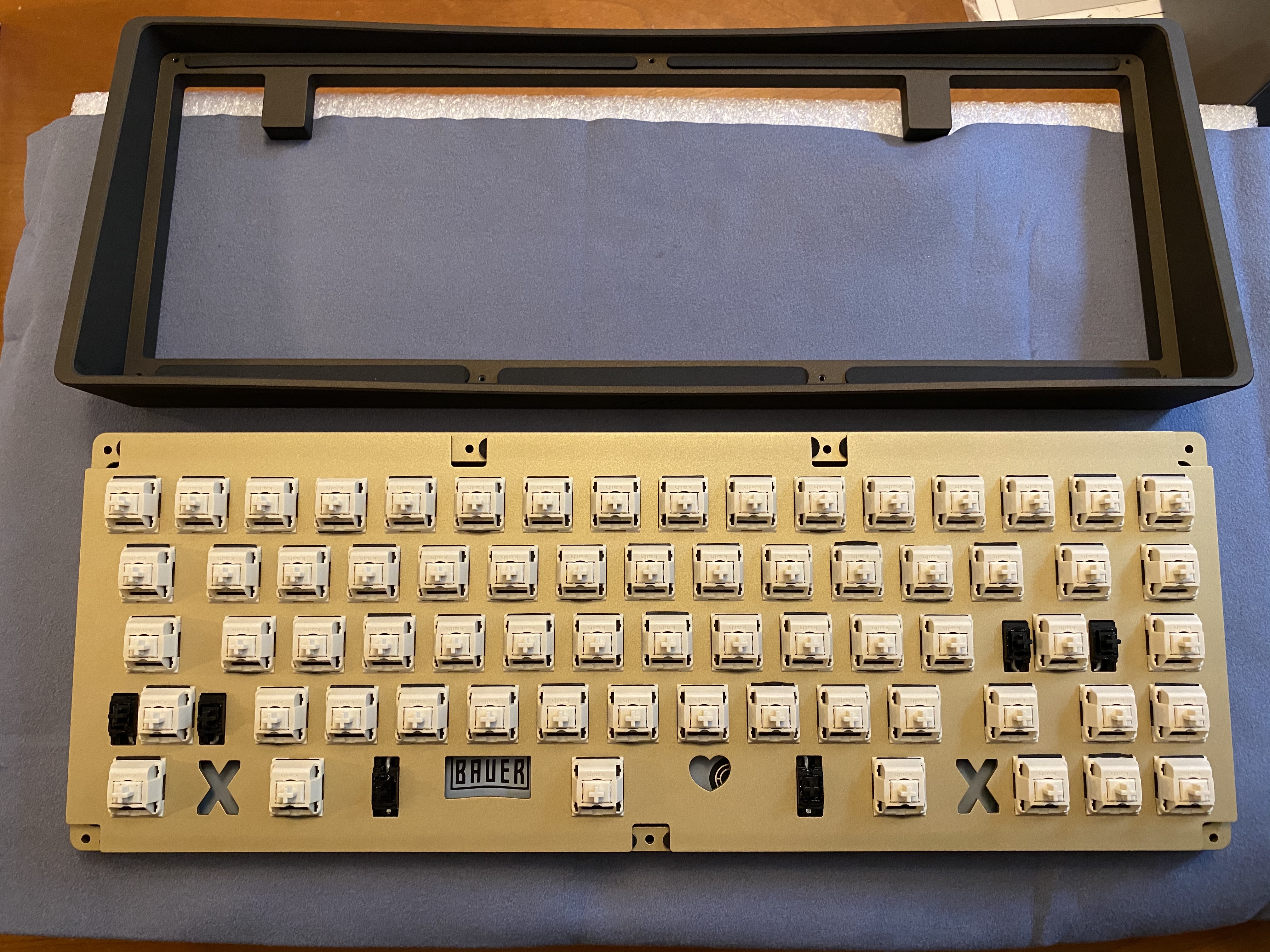
Pull
Oh, all right, you want to see that Bauer now? First look, bronze cerakote with brass plate. I’m unable to properly capture that cerakote finish, but it is flecked with very fine gold specks that catch direct light in a lovely way.
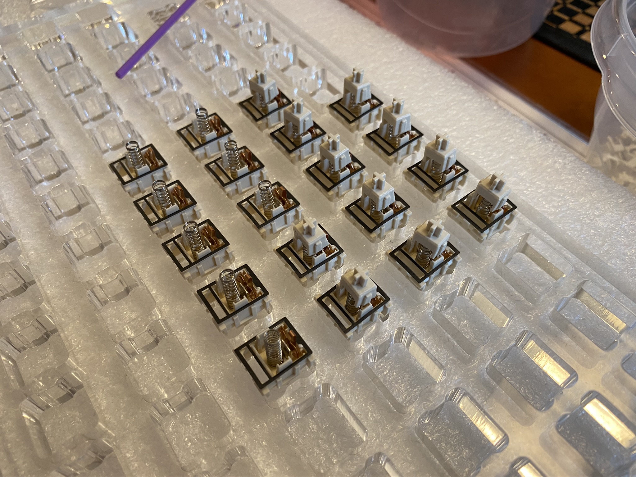
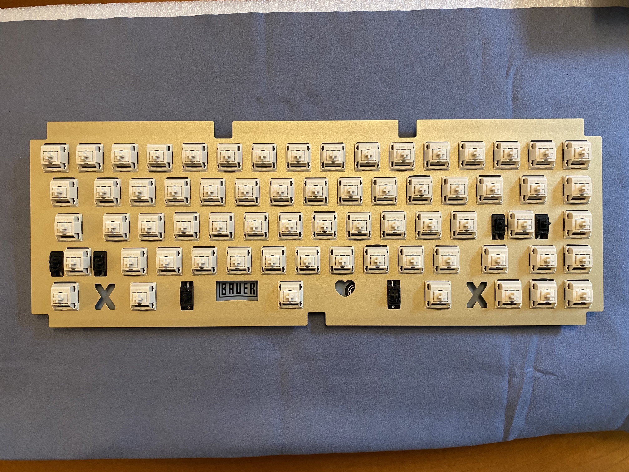
If you’ve read through the previous 38 build logs, you know how the switch and stabilizer parade goes.
If you look closely, you’ll see I wasn’t particularly precise with film alignment when putting the switches back together. I didn’t notice any difference in sound or feel as a function of film placement. With Creams, the Deskeys films make for a tight fit - you will need to inspect each switch after reassembly to make sure both sides of the top housing have fully snapped into place. I found that when I listened carefully, I could hear two separate clicks; a louder one when one side of the top housing locked into place, and a fainter one when the other snapped into place. In any case, if they aren’t properly snapped together, you’ll find that out when you try to fit them into the plate, as they won’t fit.
Next, we need to attach the daughterboard to the bottom piece of the case, and then use the included cable to attach the daughterboard to the PCB. If you happen to be one of the last stragglers, like me, who hasn’t built his Bauer yet, and your eyes are as bad as mine, then I’m here to help. Here’s how the JST connector should look when it’s attached to the PCB.
In passing, I’ll also note that the adhesive foam gaskets that you see around the perimeter of the case bottom were preinstalled. Nice.
The plate is held in place by pressure from the gaskets on the bottom and top of the case halves, so the trick here is simply placing the PCB/plate assembly on the bottom gaskets and aligning the plate with the case, and then placing the other half of the case (also equipped with gaskets, which we can see here) on top.
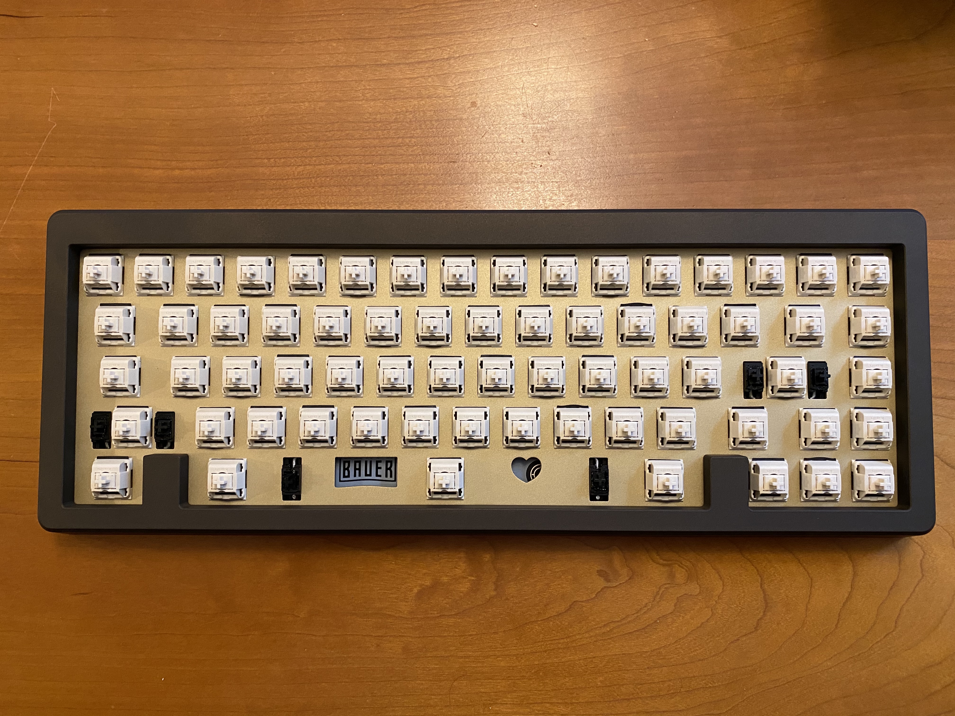
Serve
From here, it’s just a matter of (carefully!) installing the seven screws to hold the whole thing together. Here’s the underside of the Bauer, exactly as we expected from the packaging. Details matter!
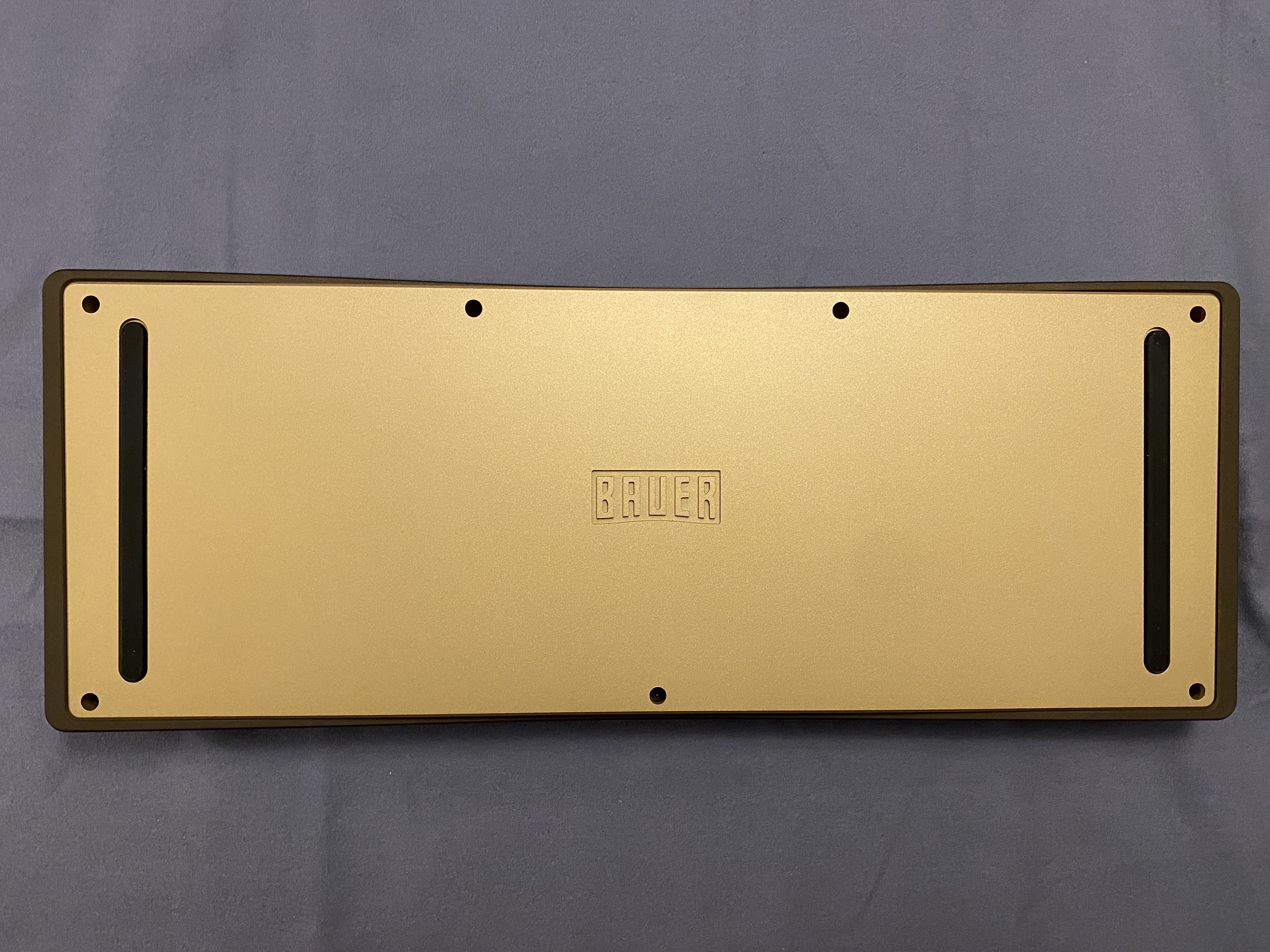
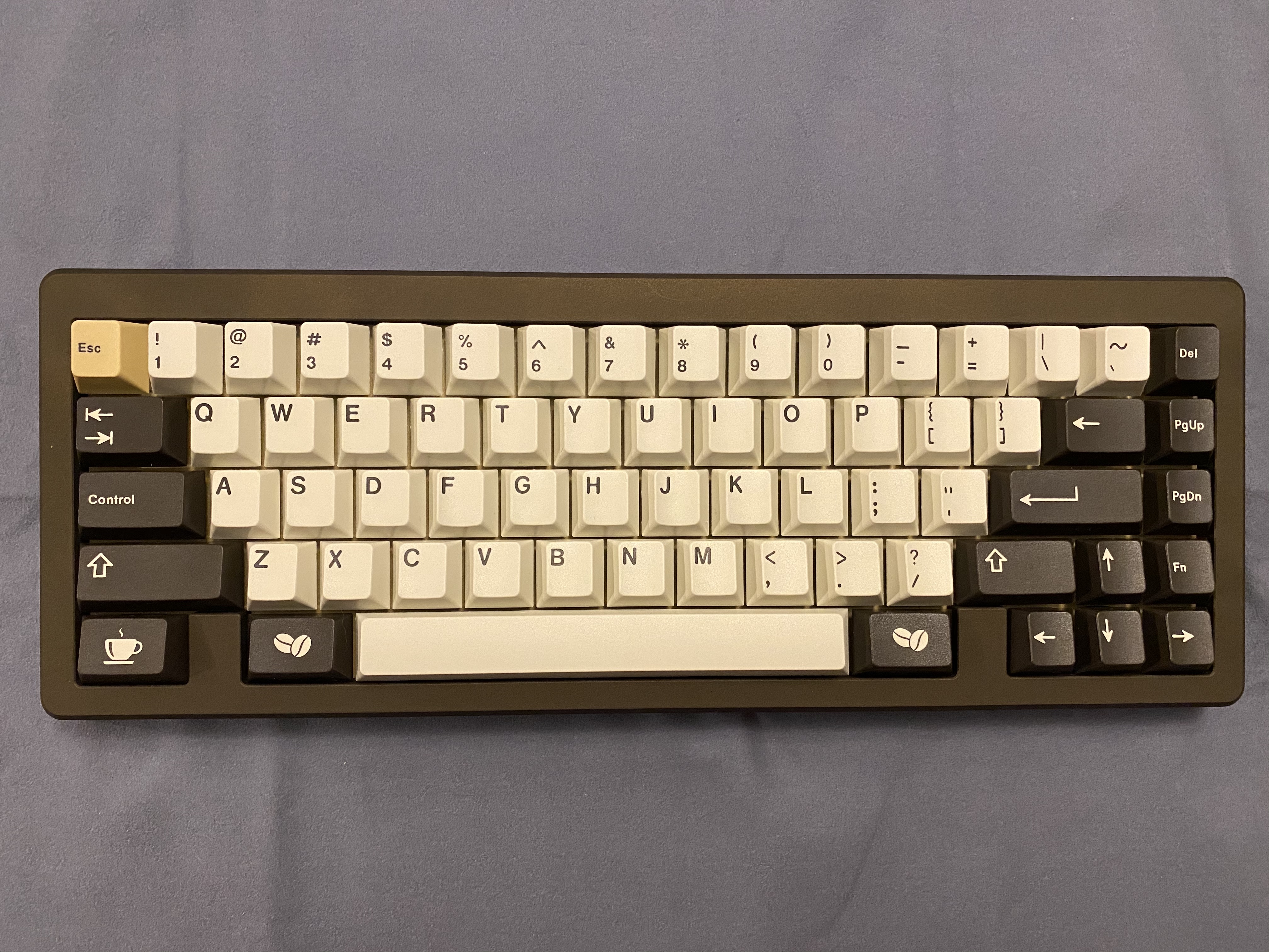
At this point, the Bauer is ready to receive keycaps.
And receive keycaps it shall, and, sometimes, our color hunches pan out. GMK Cafe turns out to be just the thing for the dark finish of this Bauer.
Lessons learned
- The sound of Cream switches is modestly but noticeably improved with the use of films; I found it to be crisper and cleaner than a stock Cream switch.
- Deskeys films seem perfectly fine to me for switch filming; they are a bit more delicate than TX films, so if creasing the films is an issue for you, you may prefer TX films.
- With preinstalled gaskets, it’s a little harder to tell, but I think the gaskets are making a significant difference in board acoustics. To see this for yourself, snap some Creams into place in the plate, and then actuate the switch while holding the plate close to your ear. You’ll hear plate ping, which is essentially gone once the plate is sandwiched between the gaskets. I initially thought I might have to use some Sorbothane or foam in this board, but it’s not needed.
- Packaging, instructions, ease of build, and quality of the Bauer kit are all well in line with what you should expect from a premium custom build, and this bodes well for the imminent Bauer 2.
I hope you’ll agree that a proper coffee service is a thing of beauty.
Specifications
case: DixieMech Bauer
- 6063 aluminum
- bronze cerakote top
- brass bottom
case dampening:
- preinstalled adhesive foam gaskets, top and bottom
PCB: WT65-B
- VIA support
plate: brass Bauer plate
plate/PCB dampening: n/a
stabilizers: GMK PCB screw-in
- 1x7u, 2x2u
stabilizer mods:
- clipped and lubed with SuperLube
- installed with cloth washers
switches: 66x NovelKeys Creams
switch mods:
- springs tub-lubed with Krytox GPL 104
- stems hand-lubed with Krytox GPL 205g0
- no housing lube
- filmed with Deskeys switch films
keycaps: GMK Café
HxWxD (without caps or feet): 1.13" x 12.88" x 4.81"
HxWxD (without caps): 1.19" x 12.88" x 4.81"
HxWxD: 1.44" x 12.88" x 4.81"
assembled weight: 2.39 kg (5.27 lb)
16 Likes