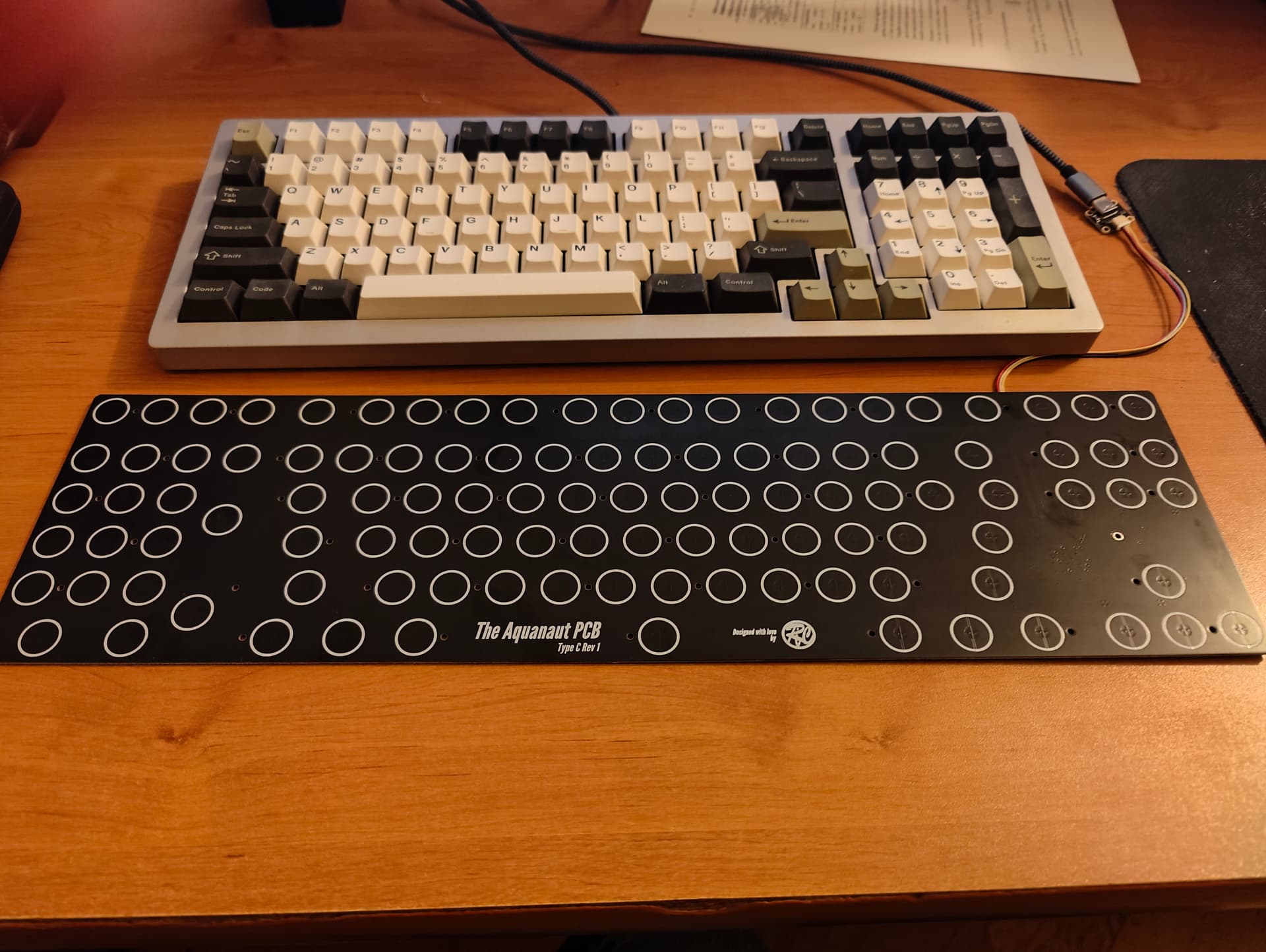
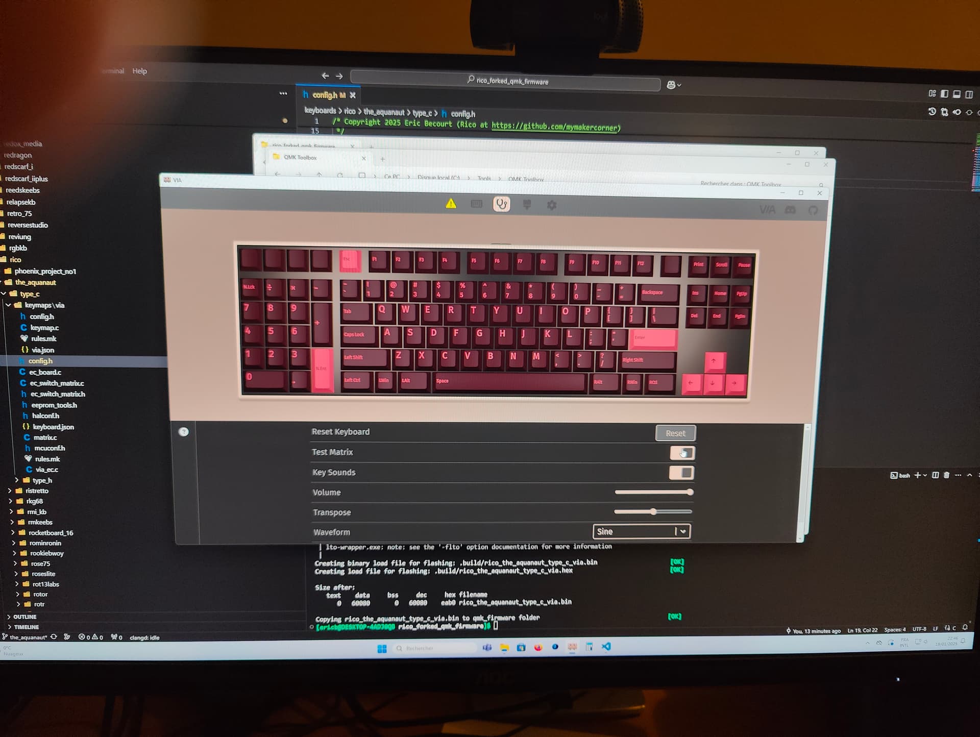
Worked on theAquanaut Type H PCB firmware and assembly today.
The PCB works flawlessly and has a working QMK VIA firmware that I wrote today
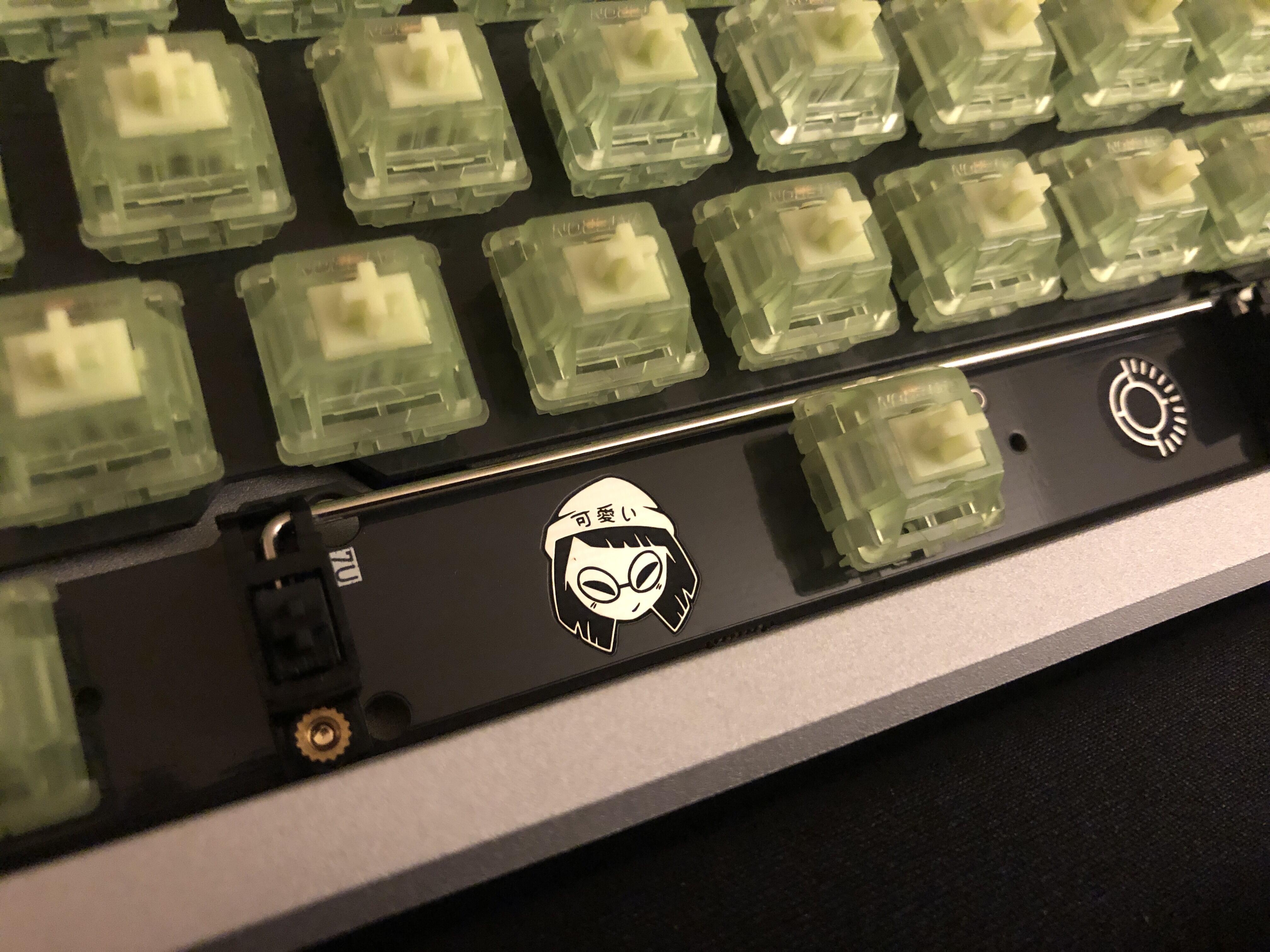
I also assembled switches (Glarses Cherry Purple) with the matching FR4 plate.
Everything have been assembled without issues.
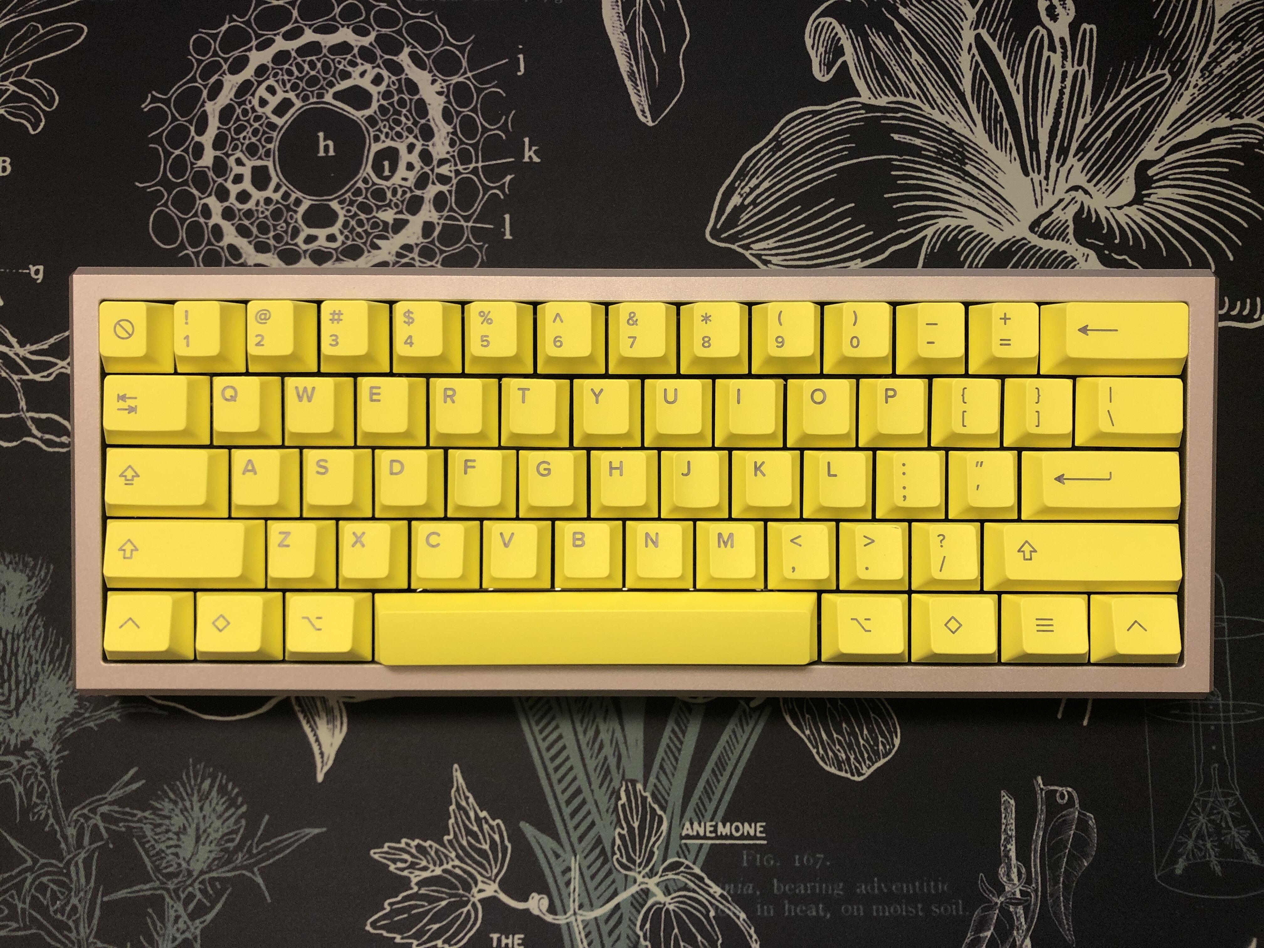
I decided to put my other argyle together. I forgot this was a prototype PCB and I was going to have to put the RGB LEDs and USB socket on. Shit.
LEDs turned out okay.
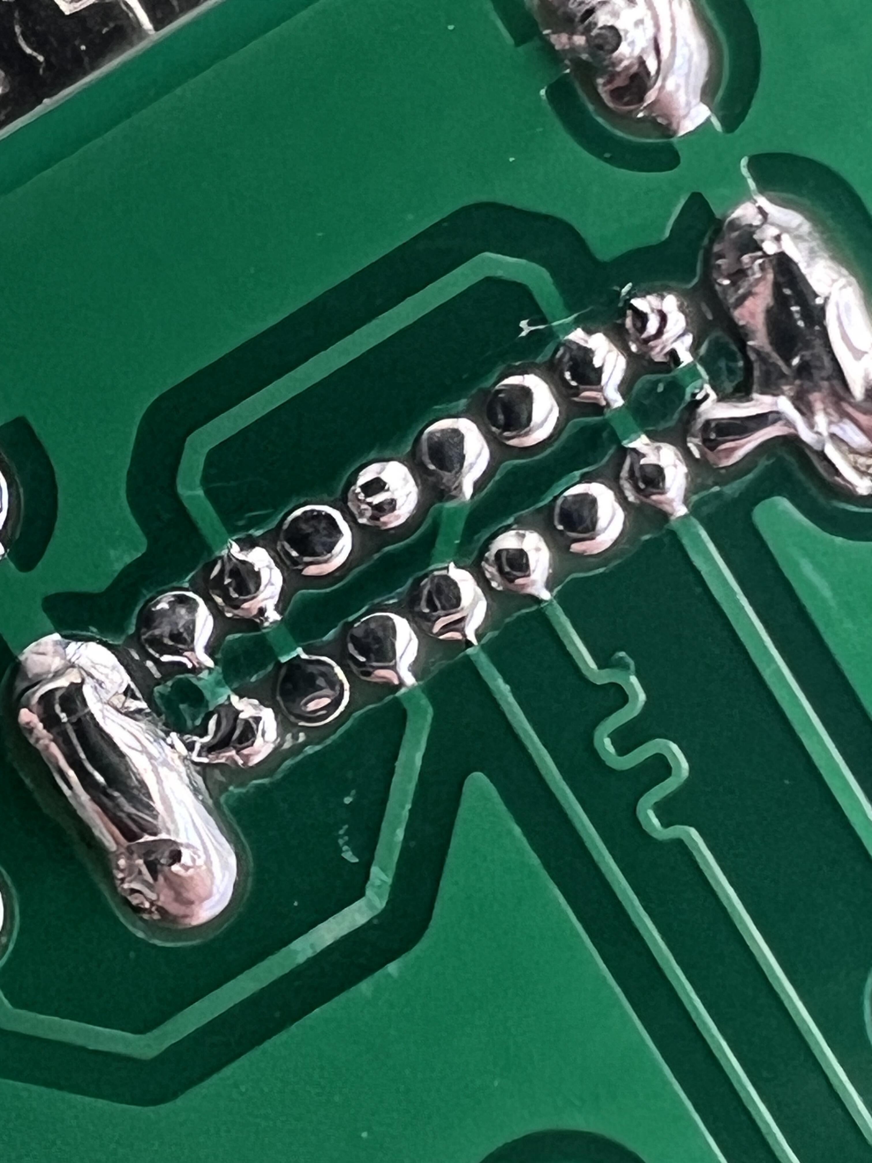
But this is my first attempt to solder on a USB-C port.
I kept checking with a multimeter and I was getting a bridge on the outer pins and the port legs. I could see a solder bridge on one so I kept taking it off and reflowing. Went through 4 or 5 attempts but I was still getting continuity.
But wait. Are those pins supposed to be fucking ground pins?
So aren’t they essentially supposed to be connected to the socket? One the one hand, I want to feel better knowing it’s good to proceed, but on the other hand I have wasted an hour trying to fix something that wasn’t messed up to begin with.
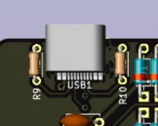
In this image to two outmost pins look connected to the shield like in your case.
Took it from: (In Stock) Argyle 60 Keyboard Extras
In this revision the USB C port has not through holes for the pins so it may be different in your case…
Just to be safe use a multimeter to see if 5V and GND are shorted or not.
If not you can plug the thing and see if it works.
Less on my workbench and more something I discovered I messed up on recently. When I took delivery of my NicePBT British Racing Green set a while back I had a pretty tight 6.25u spacebar and I used the Geon stem trimmer to loosen the stem that touches the switch.
Well it looks like over time of repeated use/dismounting and its expanded to the point where its pretty loose now, and it’ll rattle with certain switches that have smaller stems. Wrapping a little PTFE thread seal tape around the switch stem tightens it so its not a huge loss, but still a bummer to mess up a spacebar like this.
Yes, for the THT USB-C connector, the 4 outer most pins are ground pins, and the connector legs are often also connected to ground. In your picture you can see the ground plane connected to the legs.
It’s quite likely that there is a fat trace from the pin to the leg and this is guiding the heat along the trace and causing the solder to bridge over the soldermask.
Your soldering looks pretty good, those tiny pins are a PITA.
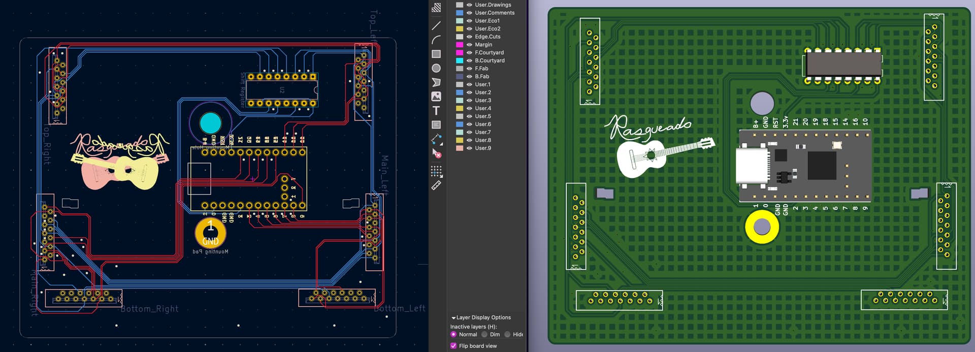
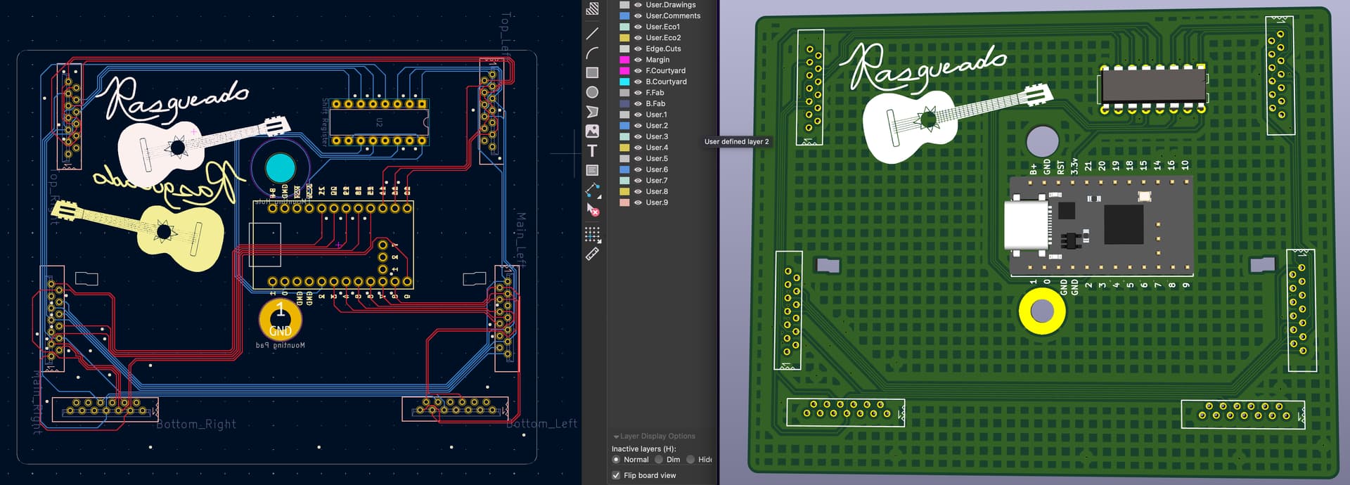
Creating a custom replacement controller for my KA2 boards that will use a Nice!Nano v2 and ZMK. Just wrapped up routing and adding a custom logo to the silkscreen layers. Now to send off the files to be manufactured!
lol, yeah it’s pretty roomy in there. Technically, I could make the board smaller, but then I’d be in a scenario where I’d be taking some of the slack out of the FRCs that connect the different boards to the main board. As this one is setup, it’s a direct drop in replacement for the existing Stapelberg controllers I have.
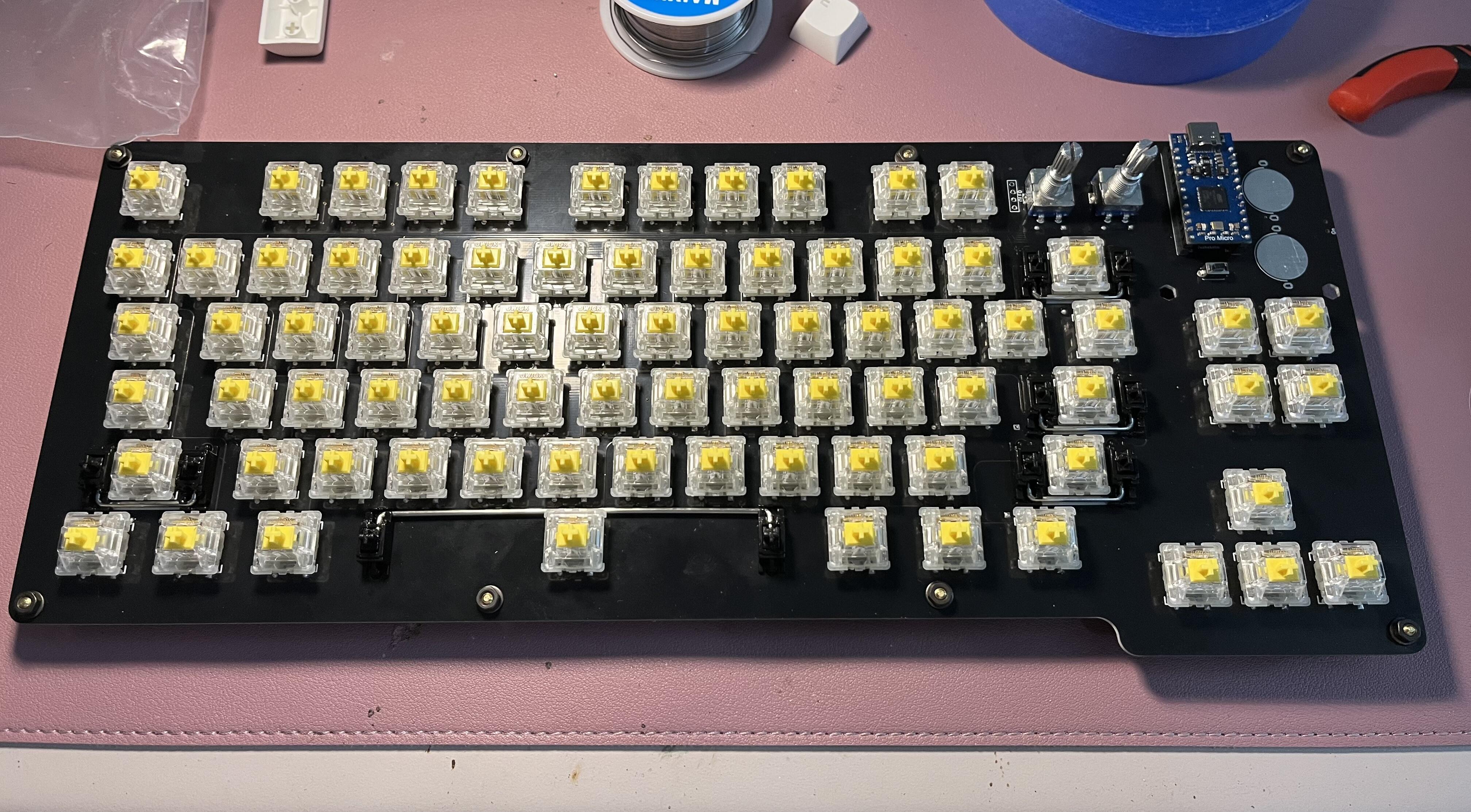
Finished soldering the Yushakobo Primer79 and getting the firmware and remapping done with the remap-keys.app online tool, which all went very smoothly. This is a PCB-mount build with JWICK 67g linears. This is actually my first time doing a build on someone else’s PCB; I reckon I did things a little bit backwards. Still haven’t decided on keycaps, but I think SA Tatooine might look nice and the kitting will work out well with my layout.
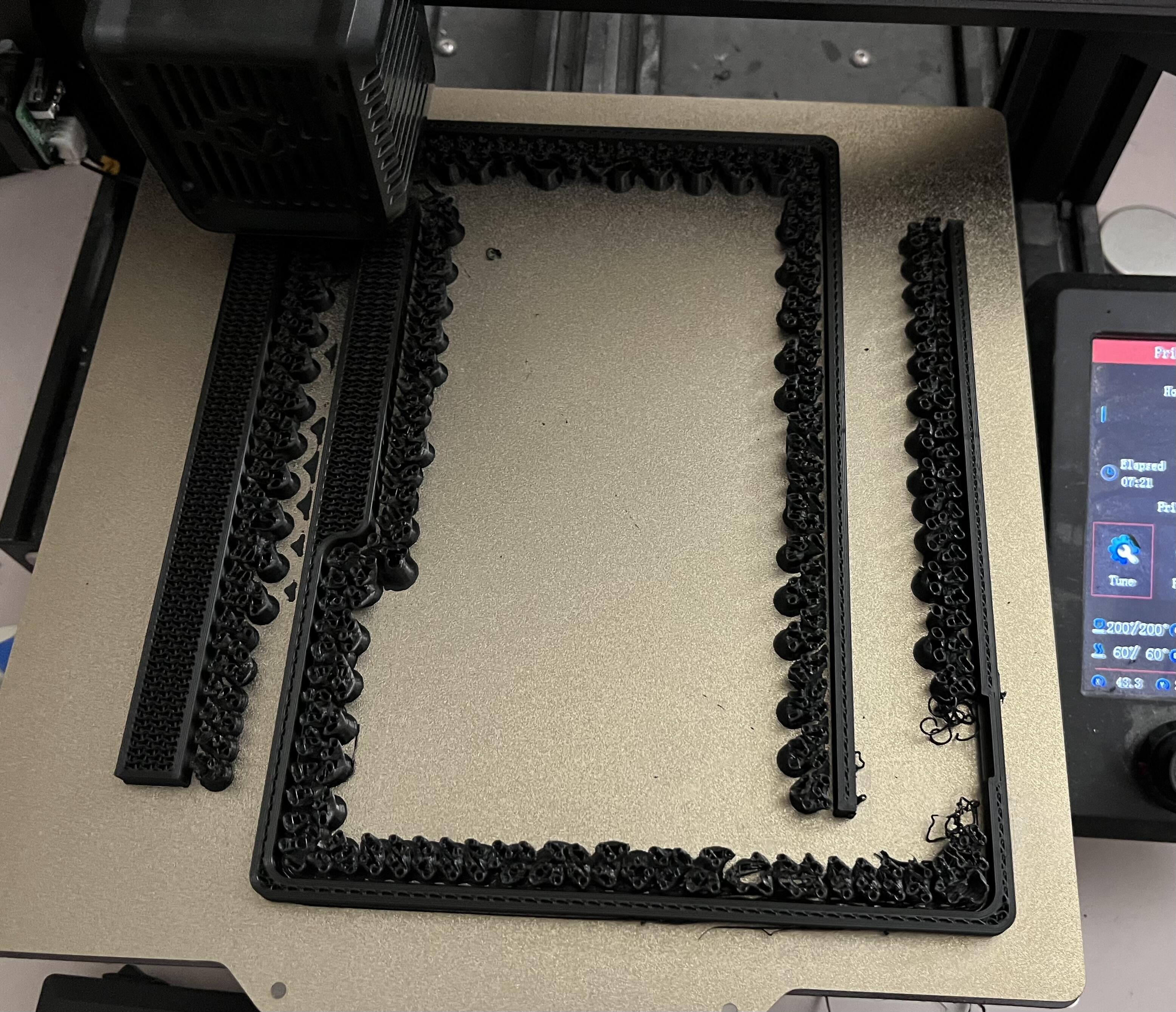
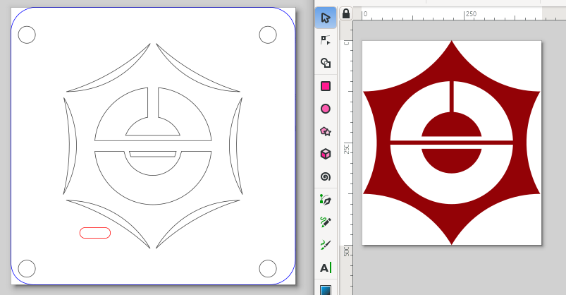
Meanwhile, the printer is working on the case, and I’m praying those ragged tree supports hold up. The weather has finally broken so I can spend some time in the garage this week getting the laser to cut the baseplate, the top “plate” of blockers, and the decorative MCU cover I ginned up in Inkscape based on the flag of Taito City, the neighborhood in Tokyo where the store is. It’s just a block or so into Taito, where most of Akihabara is in Chiyoda, which has an equally nifty flag. Pretty sure the laser can handle the resolution, and I eased the dimensions a bit to stencil-ize it and leave at least a mm everywhere. If the cutout doesn’t work, I can always etch the “proper” version onto something.
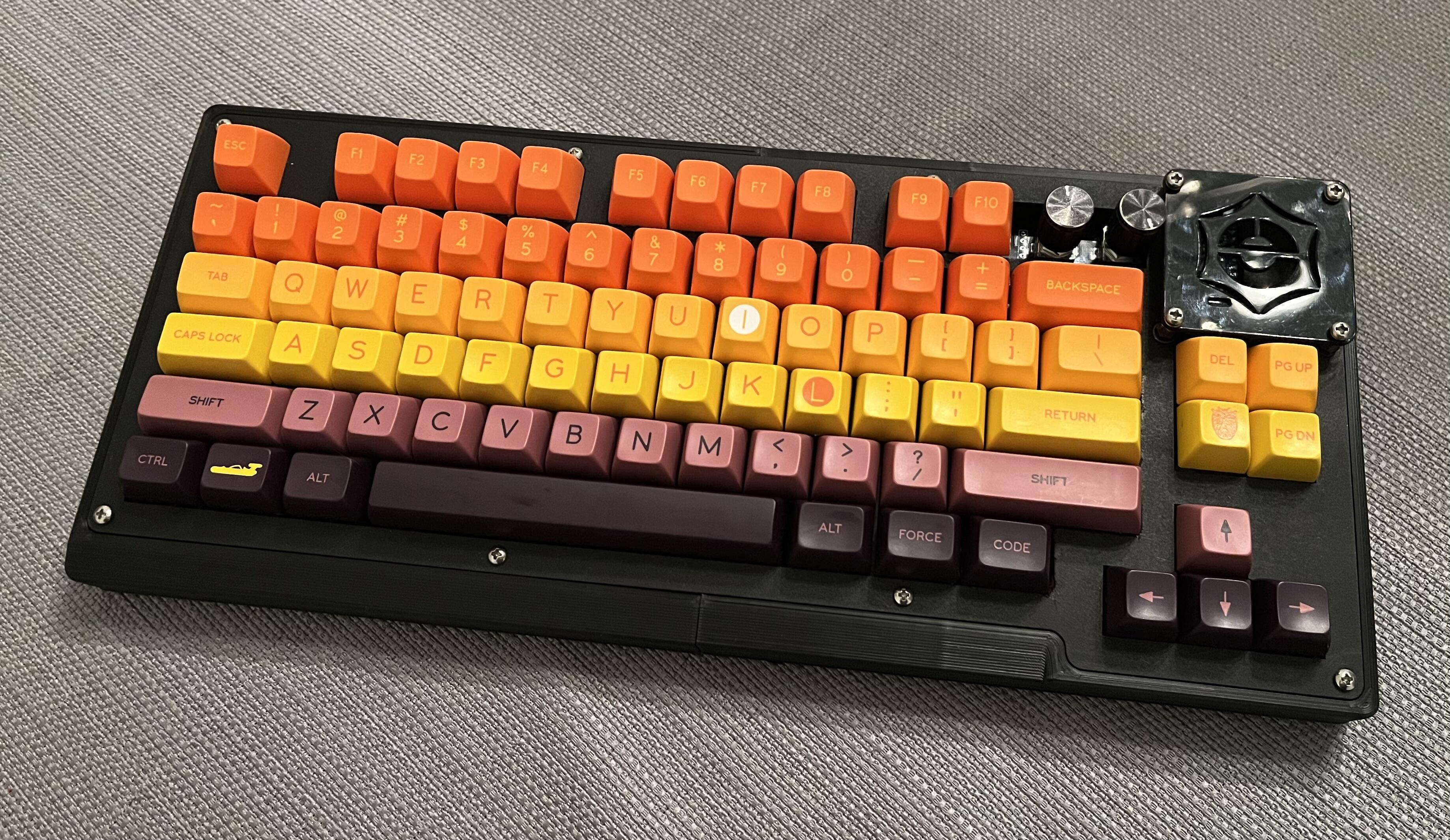
To adapt a phrase from the cycling community, behold the KSO, the keyboard shaped object!!!
It looks nice with the SA Tatooine (IMHO), though I need to sort out what’s putting that wave in my larger prints (possibly dust in the works of the Y axis, lord knows there is some). Also, however, the source files I used assume tighter tolerances than I can muster right now, so I’ve got to disassemble and make a few updates. Several keys along the right side were binding a bit on the blocker plate, and the entire bottom row is catching on the 3D-print, with the spacebar doing so far too much to consider using the board as-is.
Last question for the hive mind: what are your preferred methods to improve hollow-sounding spacebars. The fact that I care at all means this particular combination of SA on a plateless build is pretty egregious. The rest of the keys sound kinda-to-very nice, though location on the board seems to matter a lot (eg home row sounds a lot different from the F row).
Next steps:
Take it apart and trim down the inside of the 3D print to give some relief to the bottom row.
Re-work the blocker plate design to put about an additional 0.6-0.8mm outset around all the switch cutouts, and maybe conceal around the encoders a little better.
Retrofit something to help level the 3D print pieces. My theory that the PCB and other structure would force them into alignment was overly optimistic.
I use silent switches for my spacebars, like Bobagums, and the cushioning seems to absorb a lot of the noise, without it being too noticeably different from the surrounding keys. But I’m a linear person, your mileage may vary.
In a departure from my usual preferences, this one has linears. Fairly heavy ones, but linears none the less. Thanks to you and @fatalruin for the spacebar advice. Once I sort out the rest of the issues, I’ll try some foam or other cushioning. Fortunately, even if I rage-quit part of the project, this was intended to work as a bare pcb with bumpons, so I’m not at risk of losing my souvenir. Worst case will be PCBs and standoffs, though if I do that I’ll probably save the SA for a different project.
I just spring swapped 50g springs into Choc Ambients… These switches are actually incredible… and not just for low profile switches. These are genuinely the best silent switches I have ever used. They are close to or even tied with new Nixies for my favorite switch.
This time I decided to go plateless; first time I’ve tried that. Wasn’t my original plan, but the included plate didn’t support 6.25u space, and that’s what I wanted this time. Plateless it is!
Maybe not the best build to go plateless with as the PCB isn’t completely flat, but I love the bouncy feel and most of the keys sound great. The return key and a few others have that aluminum dink sound, but I love the space bar and backspace. This is mostly a thematic aesthetic build, but I think I’m going to enjoy using it, too.
I think I might re-position the FN key to what I’m used to for a 60%, the right corner - but this will do for today. I had a lot of fun with this one!
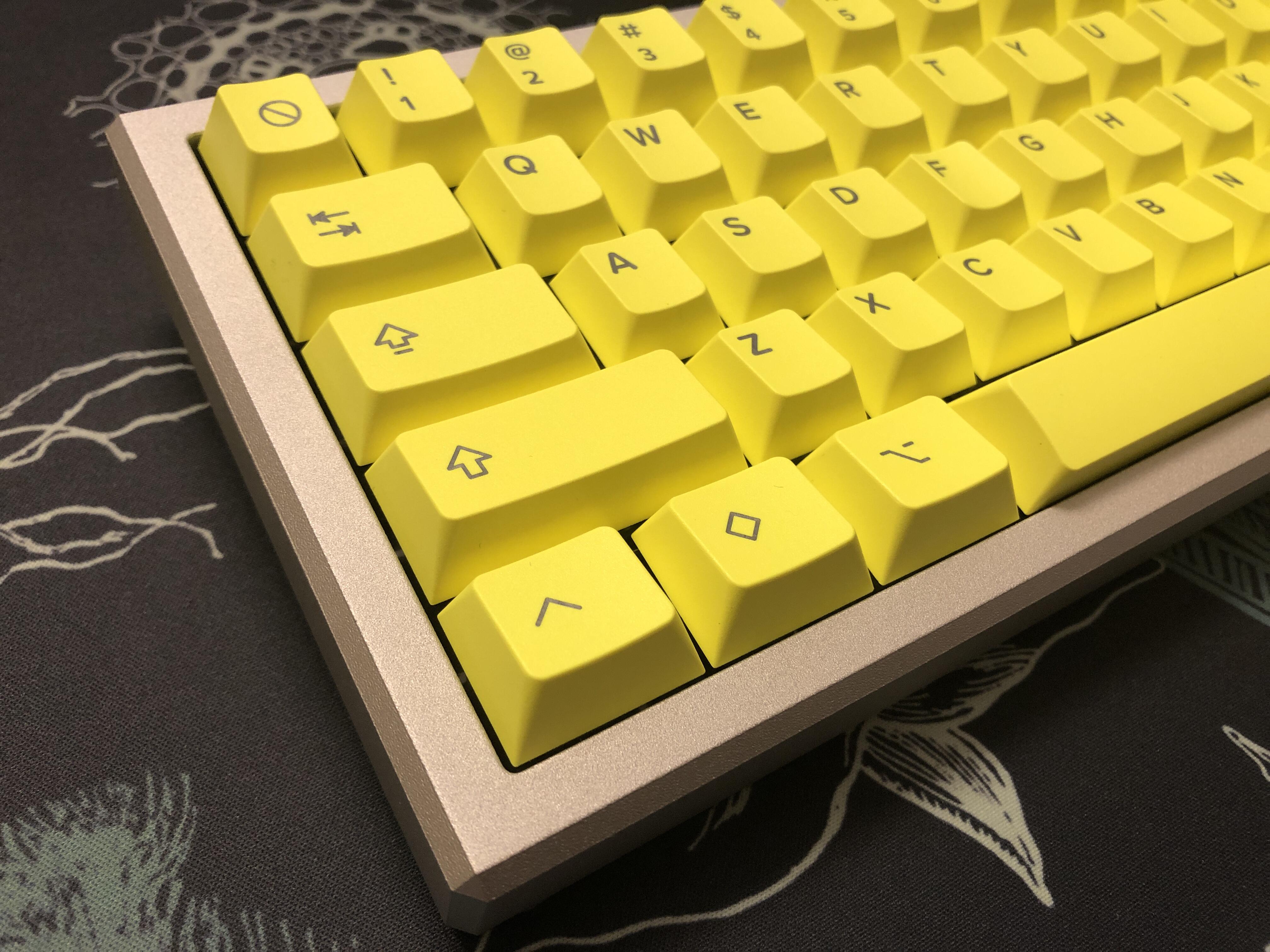
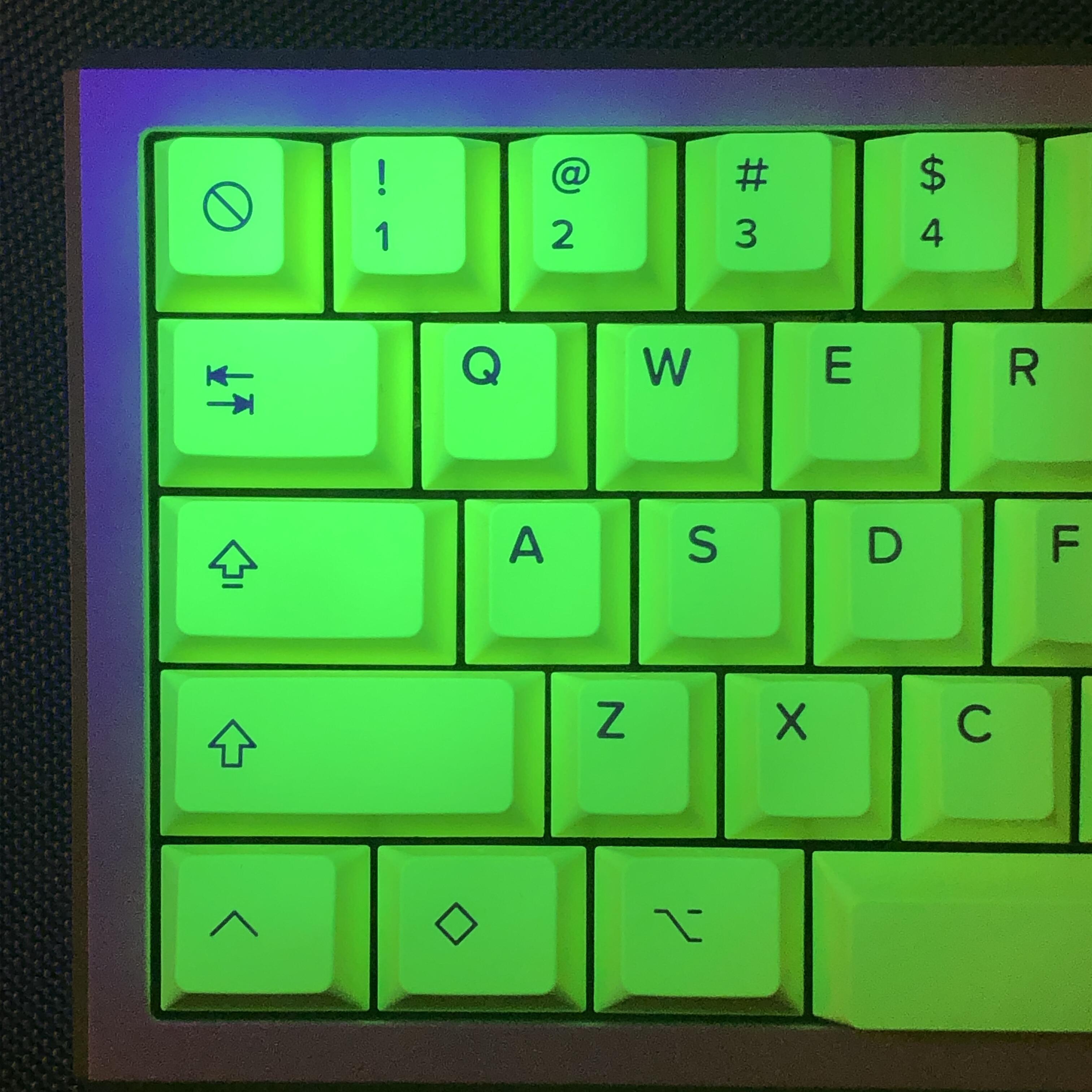
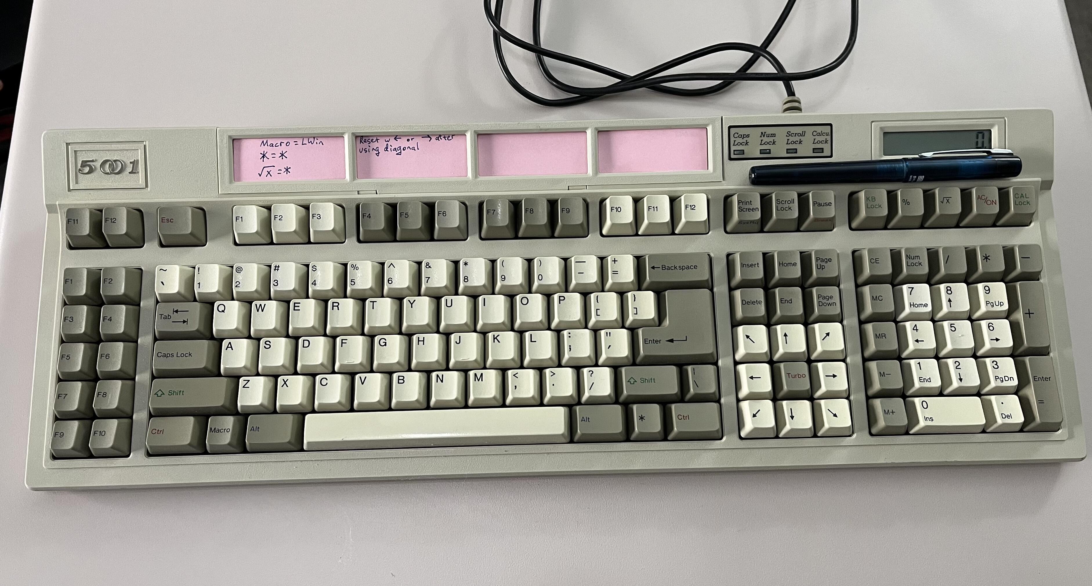
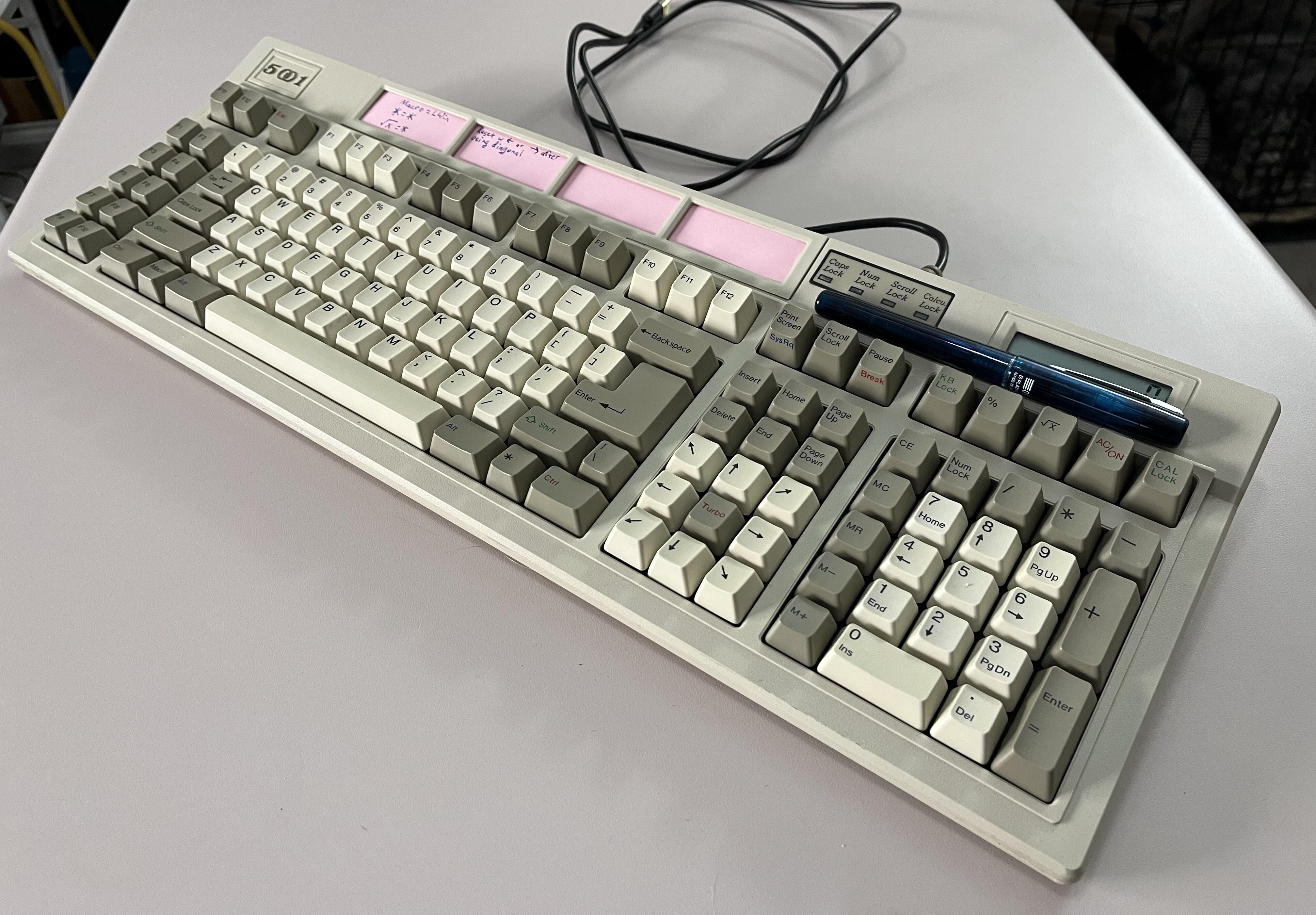
From the “Mice are a passing fad” department, comes this Focus FK-5001, though it made its debut in polite society in 1991 or 1992 as an “Ares Diamond Calc.” I got it off ebay in a lot of four boards (anybody want a Tai Hao with Alps clones?), pretty dirty and with its cord cut, implying it was written off by the accountants and retired from a workplace. I made sure the DIP switches were set to PS/2 mode and wired up a Soarer’s converter, which now lives inside the case. I also just generally cleaned everything up, and while I didn’t open up the Alps White switches, I put the narrowest nozzle I could on my shopvac and then did both suck and blow.
The Focus boards generally are quirky beasts, and this one is no different. I don’t think I’ve ever seen a product that so clearly reveals the tension between marketing and engineering:
The flip-top badge that hides the DIP switches had 5001 on one side and had an adhesive label with the OEM customer Ares on the other. It was one of those puffy foil-backed ones that almost look like epoxy, yellowed all to hell though, and it blocked use of the Focus branding, so it had to go. Underneath the raised badge was another Ares label, this one a flat sticker.
The calculator on this one is just the coin-cell model, so it actually still works as intended, including the screen. Interestingly, the keyboard matrix at least partially routes though the circuitry for the calculator, and when the calculator is removed the numpad stops working, even in keyboard mode.
Committing two buttons to “KB Lock” and “CAL Lock” just reeks of a kludgey fix, to what precisely I don’t know, but it is probably connected to the earlier (later?) models using a locking switch for CAL Lock.
It is very clear somebody was worried about the users getting confused. Shift-8 is asterisk, of course, as is the numpad asterisk. Quirkily, there is an asterisk in the lower right that is indeed asterisk too. Then, just to make sure that the 9-year-olds who’d never heard of square roots didn’t get confused, in keyboard mode the calculator’s square root key is also asterisk, I assume because there is an “X” on the legend. Out of an abundance of caution, to make sure I would not be deprived of footnotes or multiplication, I also used the Alt code (0042) and made sure it would generate an asterisk as well.
Other than that square root key, none of the other calculator specific keys generate a scan code, however, more’s the pity.
Unfortunately, the Turbo key in the middle of the arrow cluster is one that doesn’t generate a scan code. Instead, it is used to adjust repeat rate in hardware. Why?! Sigh. Also, the diagonals, at least on modern PCs, lock up after use, possibly something with how USB HID handles upstrokes? tapping left or right clears it out, though. I tried bodging the Turbo key to the down arrow to weaponize ghosting in my favor by creating an inverted T, but whatever Focus did to the matrix did not like that, so I undid it.
Ahh, the F keys… Despite “Macro” existing there, the 5001 does not act like a 9001 with its famous hardware macro programmability. I understand that some DOS software suites used the Macro button for… something, but I do not know what. On this board, it works as the Left Windows/Super key. I honestly do not remember if the Soarer’s does that by default, or if I was tinkering with the keymap before Christmas. Regardless, This board lets you choose to use either XT style F keys with F11 and F12 thrown up there very casually, or use an almost normal (groups of 3 instead of 4) Enhanced keyboard F row. I assume this minimized SKUs and appealed to the grumpy 80s nerds who didn’t want to give up hunting for their function keys to the left.
Above the F Row is a slightly rickety tilting frame into which you can slide pre-printed info cards for your software suites, or you can just plop a folded sliver of pink printer paper in there.
Inside, the famous Focus (lack of) quality is there. I managed not to break the sliding tabs (better than modern snapping tabs I guess), but only because I’d looked up a teardown before. Inside, there are so very many unused screwholes, and with no wear to imply anyone had been spelunking in there before me. Nope, wires, four clips, and four wide-thread screws biting directly into the plastic is all you should need.
Thoughtfully, though, the guide for the DIP switches and directions on how to find them are actually molded into the bottom of the case.
The actual typing feel is pretty nice. The clicky Alps Whites are very tactile, to the point where I think maybe I should have opened up the switches after all, but I am not quite sure. Not quite the blessed racket of buckling springs, but generally pretty clattery and nice. The click sound is actually mostly drowned out by more plasticy bottoming-out sounds when you’re a heavy typist, but it all comes together reasonably nicely, and it’s more evidence that both clickies and tactiles suffered somewhat by Cherry MX being the last man standing when mech boards began their renaissance in the marketplace.
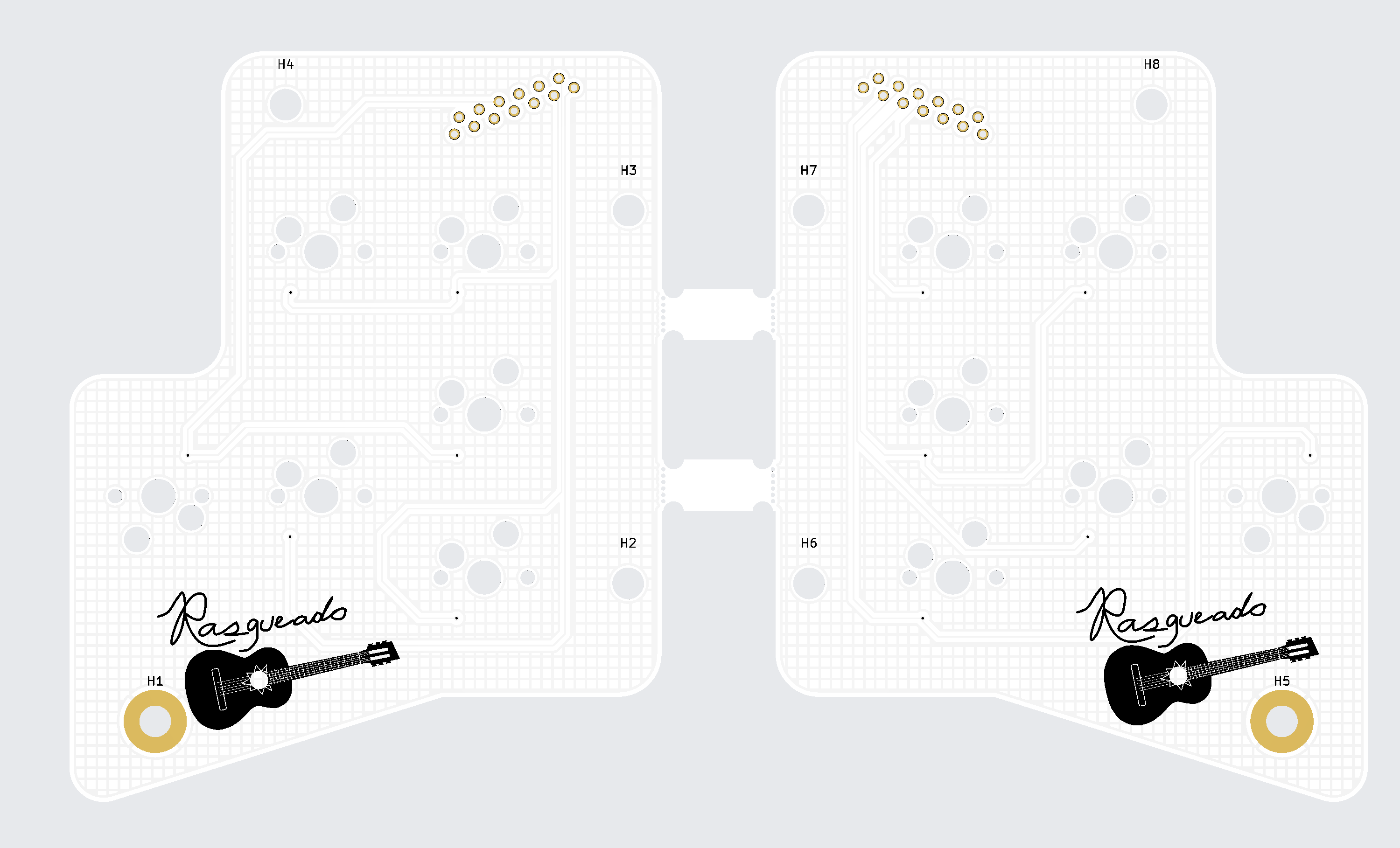
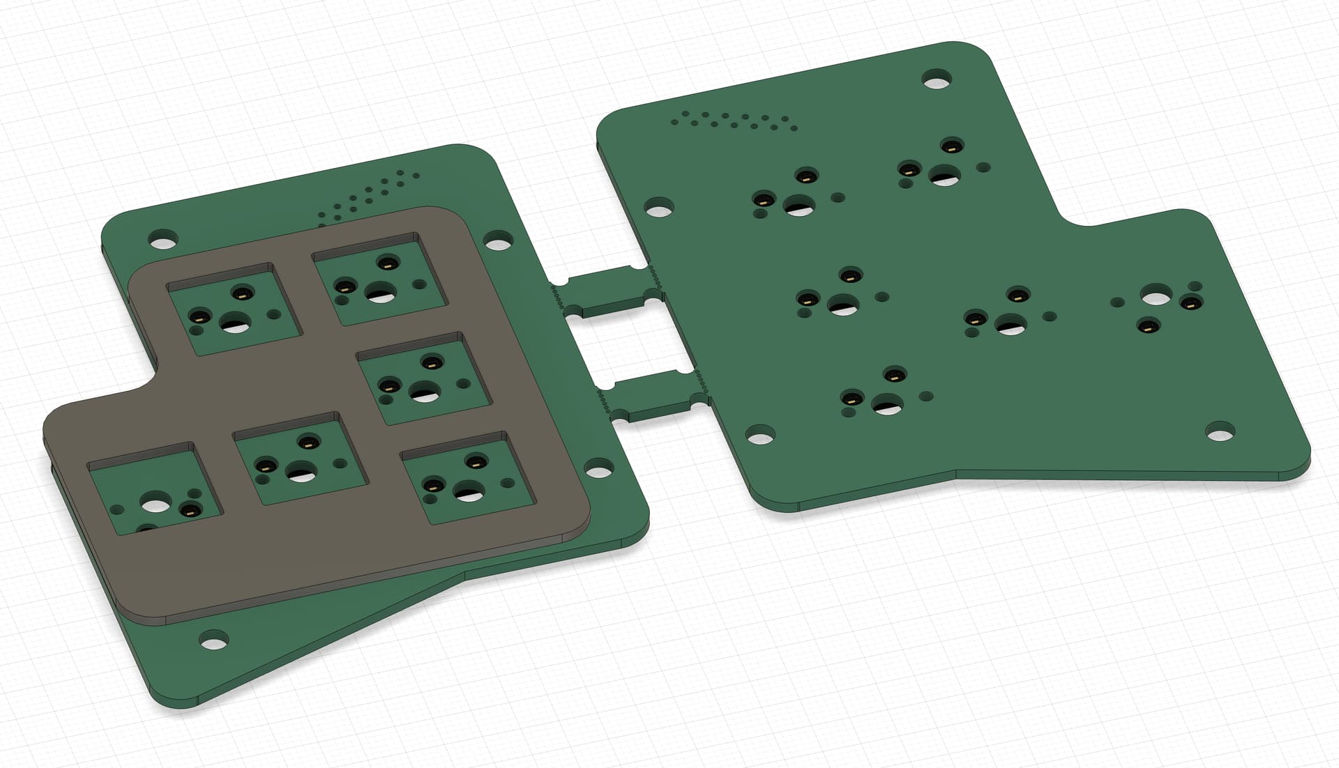
Now that the bug has fully bitten me… I designed some PCBs for my KA2 thumb clusters as well as a plate for the thumb clusters to go with the replacement board that I designed earlier.
The PCBs are hot swap and will have the diodes on the boards instead of in the switch housing like the original PCBs. I used the “mousebites + breakaway tabs” technique that I picked up from what was done on the Geist Totem to get two halves of a PCB manufactured in one go instead of ending up with two orders to get the two sides done.
The plate could have been larger, but I wanted to give myself room to play with tolerances (especially around the mounting holes) just in case something wasn’t perfectly measured out. These will be created out of carbon fiber because I love the material and CNC Madness does amazing work at very fair prices.