I see DaveK!
4 Likes
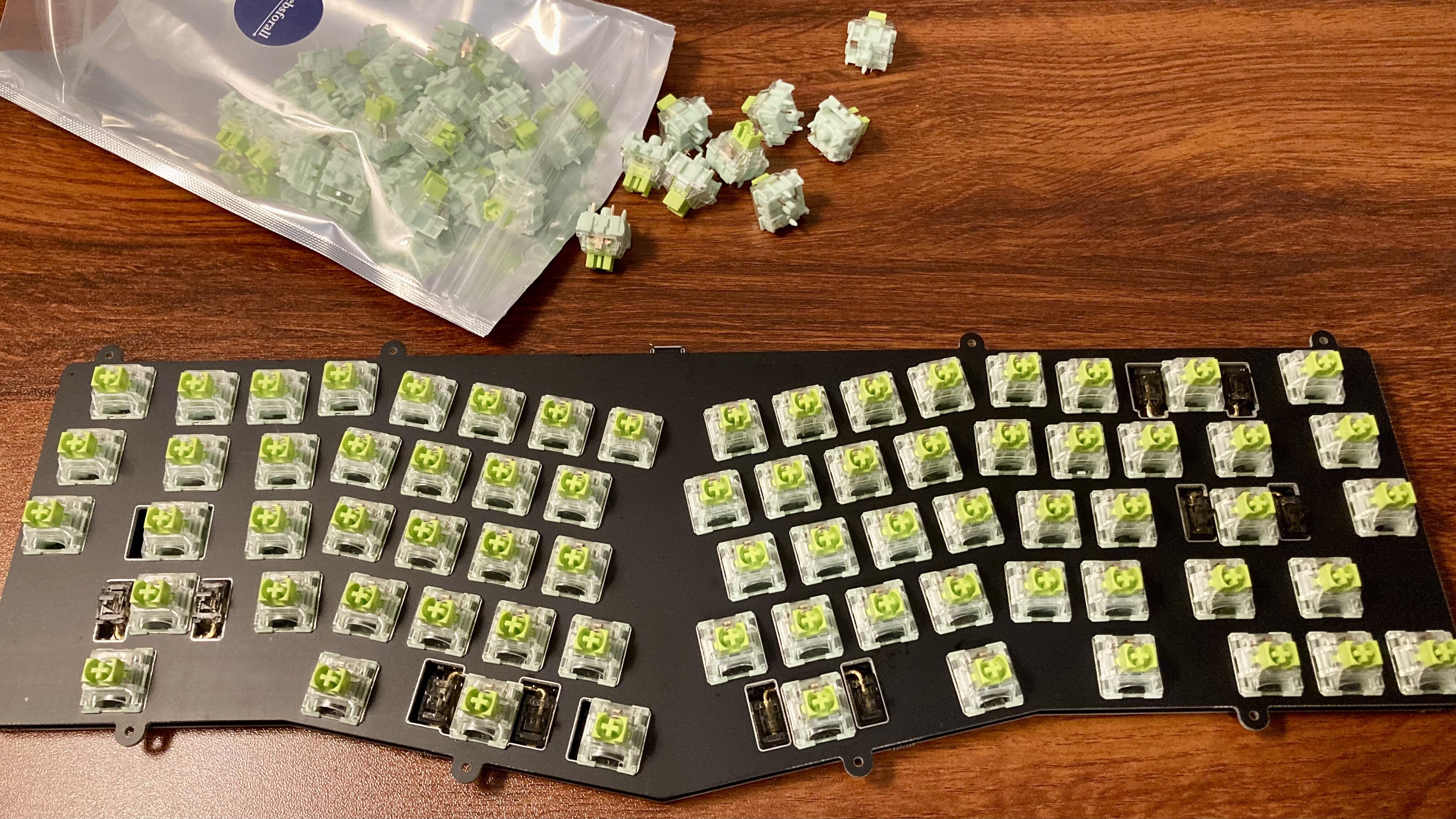
Well… sometimes things just don’t work out. Ugh. I’ve used these milmax sockets on a few boards without issue, but this was an exercise in frustration.
My normal process is to put a socket on each switch pin, insert it into the board, and then carefully solder the socket into the board. Of course, the trick here is to make sure your solder doesn’t overflow the top of the socket and get down into the switch pin area of the milmax socket.
So I got a socket on all of the switches, inserted all of the switches into the board and began soldering. The top row I failed on five out of 12 switches. Yikes.
Getting milmax out is a pain in the ass. My fingers are burned in both hands, but all is back to square 1.
I think it may have to do with the surface area of the pads on the back of the PCB. Maybe @Dave can comment. It seems like the pads are fairly small around the holes. So maybe there’s not enough surface area for my iron to heat the pad to high enough temperature for the opposite side to want to accept solder? I could try to apply flux to all of the holes before inserting the sockets maybe? Dunno.
Done for today though.
EDIT… Because I can’t leave well enough alone:
I found the flux idea worked. Not sure how I feel about the cleanup that will have to happen later from the flux residue. Boo.
5 Likes
Started using really thin solder 0.015-in for everything except switches. It is easier to control especially in tight spots. I milmaxed mine with this method.
Other than that you can try adding the solder directly to the iron tip instead of the pad so it applies more consistently (not ideal best practice but in desperate times might help)
Flux works too but dread the cleanup micro apply with a syringe as needed.
If you get really stuck think I kept an extra pcb. Stoked to see how it comes out!
3 Likes
Gorgeous and impressive!
Say more about the stickers and labels.
I’ve got this going on.
Malicious Ergo plate and PCB with stabs and TTC Aces ready to become my first soldering victims tomorrow. Really pleased with the fitment and look of the Durock smokey screw-ins and the Aces on this, though of course they’ll be covered. It’s the navy blue case.
4 Likes
Tried a new technique for removing a misbehaving USB connector.
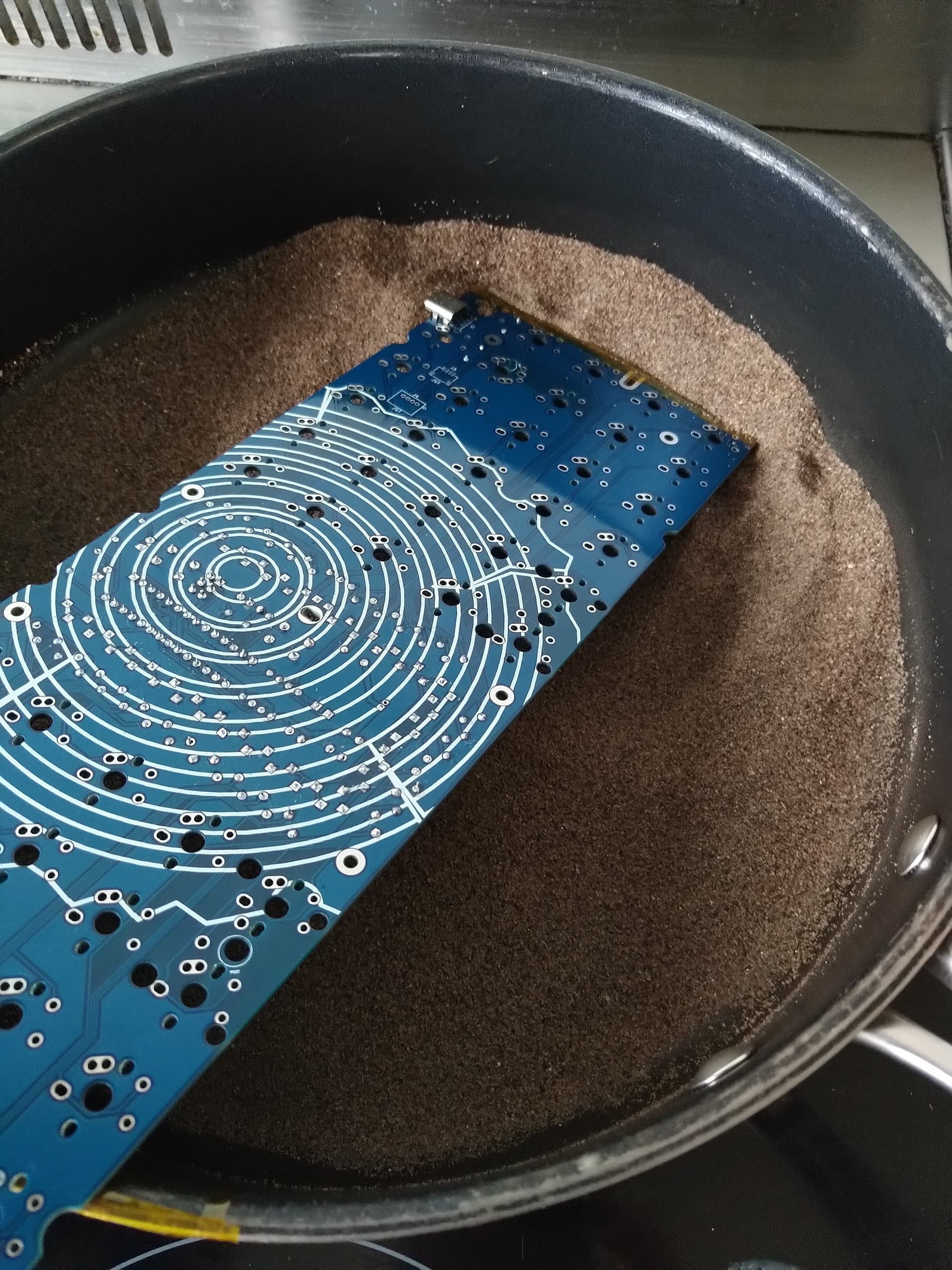
Commandeered an old pan that is now has a new life as a sand soldering pan. It’s not quite big enough to fit a 60% PCB in, so a little imaginative sand placement and some kapton tape seemed to do the trick.
My usual SMD soldering hot plate doesn’t go hot enough to melt the solder, but the kitchen stove on full power is just hot about enough. Even though I tried to protect the PCB with kapton tape, I’ve discoloured it a little along the edge in the sand.
12 Likes
Who needs a hot air station when you can have a sand pan! ![]()
Did you successfully remove the USB connector?
Yes popped right off.
6 Likes
That’s a really cool idea. Getting those connectors off with out damaging pcb is tough. How long did it take to heat up the sand?
(A couple weeks ago, I soldered on a bunch of jst ph connectors for 15 daughter boards before realizing a mistake. Those connectors were relatively expensive after many failures was able to save them by using hot air station on the back of the pcb occasionally taping the pcb till they fell off about 15-30 seconds.)
4 Likes
This is a USB4085-GF-A through hole USB-C connector, so 16 little through hole pins plus the legs. If it was surface mount I would have used lower temperature solder paste and could have put it on the hotplate I use for SMD, but the hotplate can’t get hot enough.
The sand only takes a few minutes to get up to temperature and then I could just pull the connector off with a pair of tweezers. I had to run the extractor hood on full power to get rid of all the burning sand impurities smell.
Certainly a lot easier than my previous attempts of covering all the pins with a big blob of solder and trying to get them all hot at the same time whilst also yanking on the connector.
I’ve discoloured the solder mask in a few places, I tried to protect it with kapton tape, but it’s probably impossible not to.
3 Likes
Wow, so neat! Maybe a stovetop griddle would allow the PCB to lay flat ![]()
3 Likes
At first I was just using the jars, but when SeoBun released some of her illustrations as stickers, they just seemed too perfect not to use - and that more or less kicked-off my new sub-hobby of finding fun stickers for the switch jars.
Some of the stickers are directly representational, like the aforementioned ones - they feature a depiction of the switch, often surrounded by other items of a similar color theme.
Plenty of other stickers are less direct, and relate to the switches on some other level - sometimes purely aesthetic, sometimes a riff on the name, sometimes the color, etc.
Some examples:
-
Creams - Image of the switch with cream pitcher & flower (literal, namesake, & thematic)
-
Zeal Clickies - Screaming Brick Tamland sticker (“LOUD NOISES!”)
-
Silk Emeralds - Mountain Dew Baja Blast logo (color)
-
JWICK T1s - John Wick (brand name)
-
TTC Wilds - Outdoor Adventure badge (thematic)
-
Cobalts - Cobalt periodic element square (namesake)
-
Silent Lemons - Screaming Lemongrab (lol)
3 Likes
Success! Got serious with it. Magnification headset, flux, and my newest, smallest, sharpest chisel point tip. Slow and steady. Gotta let the IPA dry a bit before I test it. ![]()
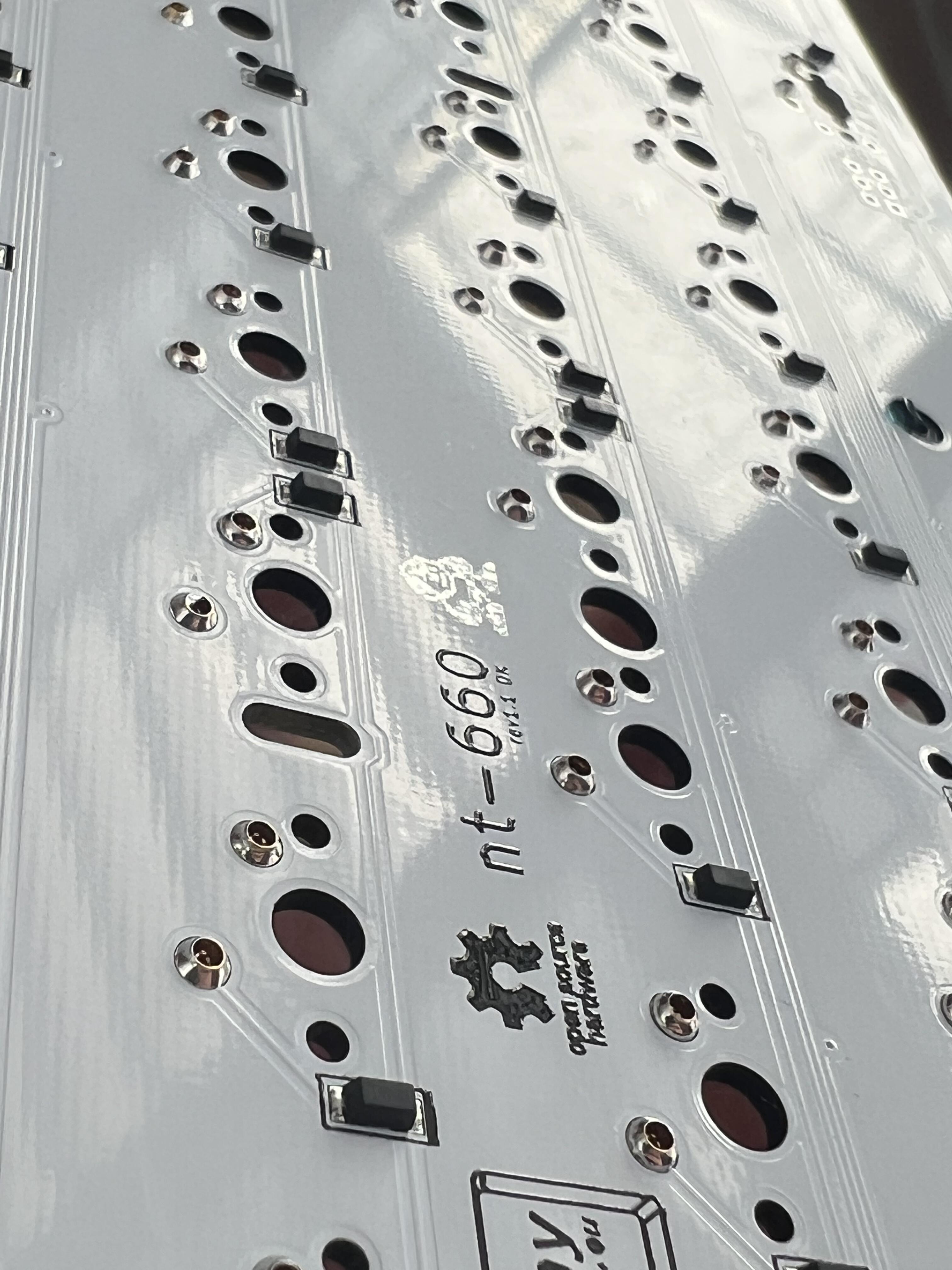
Best feeling ever right here. No bent pins. ![]() First try:
First try:
16 Likes
Amazing!
2 Likes
Those are nice solder joints, congrats!
2 Likes
Planning to solder a board later this afternoon and I’m looking for some advice:
I just realized that the switches I built for the job (some frankens with Akko Brown housings) are only 3-pin! It’s been a while since I’ve even thought about 3-pin switches and it didn’t even occur to me while I was lubing, etc that I didn’t like to use them for solder boards.
My biggest concern is alignment of the split backspace and split r-shift switches since they don’t have the plate to keep them reasonably straight (n/s).
Does anyone have a strategy or any tips on keeping 3-pin switches aligned correctly while soldering? (especially for switch in “open” positions on the plate)? I do have a glue gun but that seems messy.
I’m tempted to start over again and make different switches (I like the way these switches worked out but not enough to risk having bad alignment).
Thanks in advance!
3 Likes
I use a 3U-spacebar with three stems to hold three switches in line.
Helps a lot with alignment, and you even may do this in ‘‘steps’’, meaning you always use one switch that’s already soldered in place as some kind of an anchor point, when soldering in the other two in.
5 Likes
sounds like a great idea. I will dig around to try and find a 3U spacebar. I’m pretty sure I have one somewhere.
thanks!
It has to be a POS key I believe. I also believe you can pick up a POS from PMK for relatively cheap.
@63n was right on! I found a few 3U bars in the spacebar set for MT3 Elvish (or really the elvish set of the most recent MT3 LOTR run). The stab holes perfectly align with a 3 1U spaced switches so it will work for aligning the split-bs switches for sure. I’ll have to experiment a little with the split r-shift caps. I might have to use a 3U hanging off the edge since a 2U won’t work and the space between a 1.75 shift and the cap next to it probably won’t align with with a stab and a bar.
Interestingly there’s a 4U spacebar as well in there which I didn’t know existed. It aligns the 1st and 4th keycaps only so it’s not as useful as the 3U bar but it might do in a pinch.
2 Likes
What I do when soldering 3-pin switches or plateless build is soldering only one of the pins first then put keycaps on to find misaligned keys. With only one pin soldered, it’s much easier to realign to [near-]perfection. Once realigned, the soldered pin will help with keeping the switch aligned while the other pin is soldered.
3 Likes