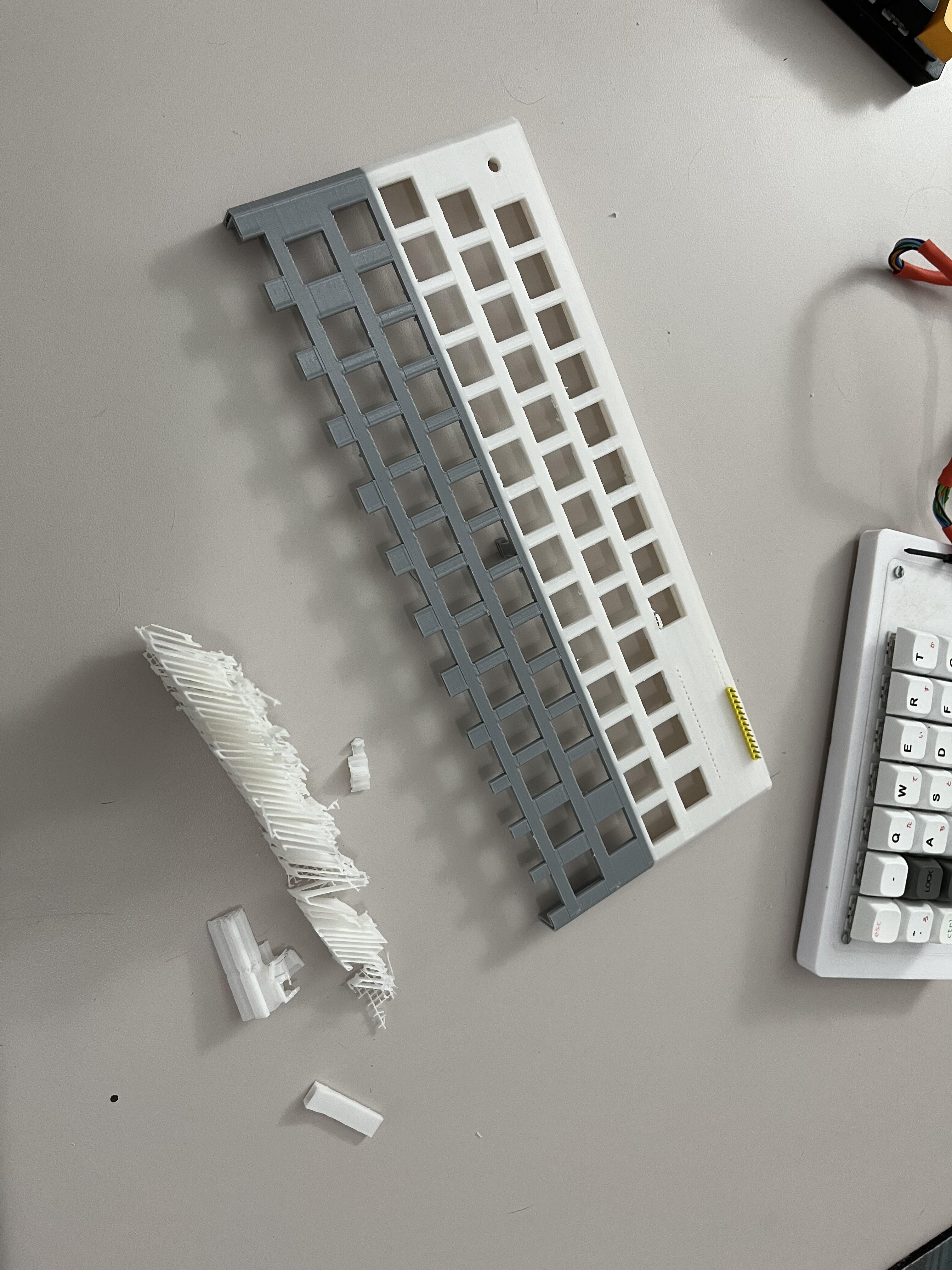
Replying to myself. I did a first print on the “print-in-place” keyboard. I was low on filament, so I figured I’d start printing with what was left and see what happens; there are a lot of unknowns for me with this. the remaining PLA filament made it about halfway through, so I decided to throw on a very old partial roll I’d been using with my 3D pen, to see if it might finish. That got to about 80% done before it snapped on a tangle (always a possibility when you let any of the filament get loose from the spool… it never rewinds quite right). No great loss, though, this one was always more of a dry run.
Lessons learned:
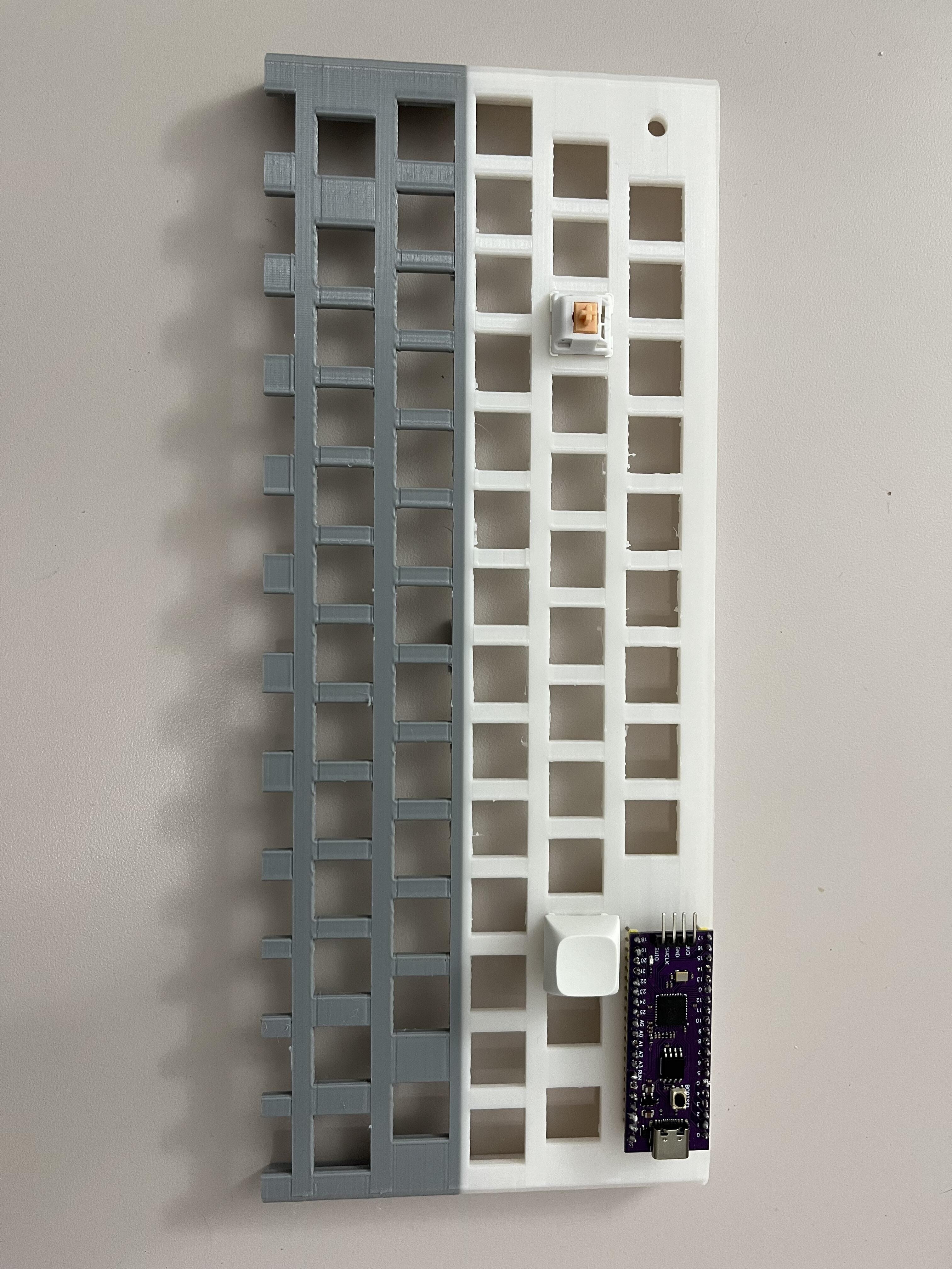
The 2.54mm header pin holes to mount the MCU actually printed great. Almost usable as-is, and easy to expand just a touch.
Most of the layout itself printed, and it seems like it will be fine for what it is.
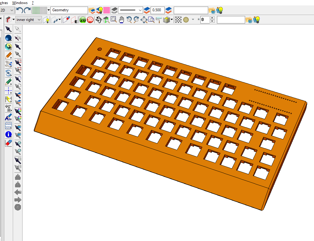
The vertical print orientation should mean I can extend the front of the model into a taper that might drastically reduce the number of supports. I need need to noodle with Fusion a bit.
With a top-mounted MCU, I think I can shave another 2mm off the bottom, and make the whole thing a bit thinner. This should also mean a less visually jarring taper at the front.
I can increase the plate thickness from 3mm to 4.5mm and still have room to do my soldering.
Some notches or thinning along the north edge of the switch openings will be worthwhile, especially with the increased friction elsewhere.
External walls could stand to be a little thicker, maybe just another mm
Infill or walls have to go up, print time be damned. Prints are indeed weak along their layer lines, so I can’t double down on that issue and have the thing be hollow too. Once the first 30 minutes are printed, my cheap Ender 3 clone generally does a good job anyway, and I can just check on it later.
Round two is fresh off the digital workbench, though not yet to the printer. Taper and angles designed to minimize the need for disposable support plastic. The print settings will be cranked up to 11, which is to say I’m just going to print it solid, since it’s inherently light (no more than 200g before caps, wires, etc.) so even if I get diminishing returns on the strength, the mass itself is helpful.
With apologies to Edison, I have not failed, I’ve just found 10,000two things that didn’t work.
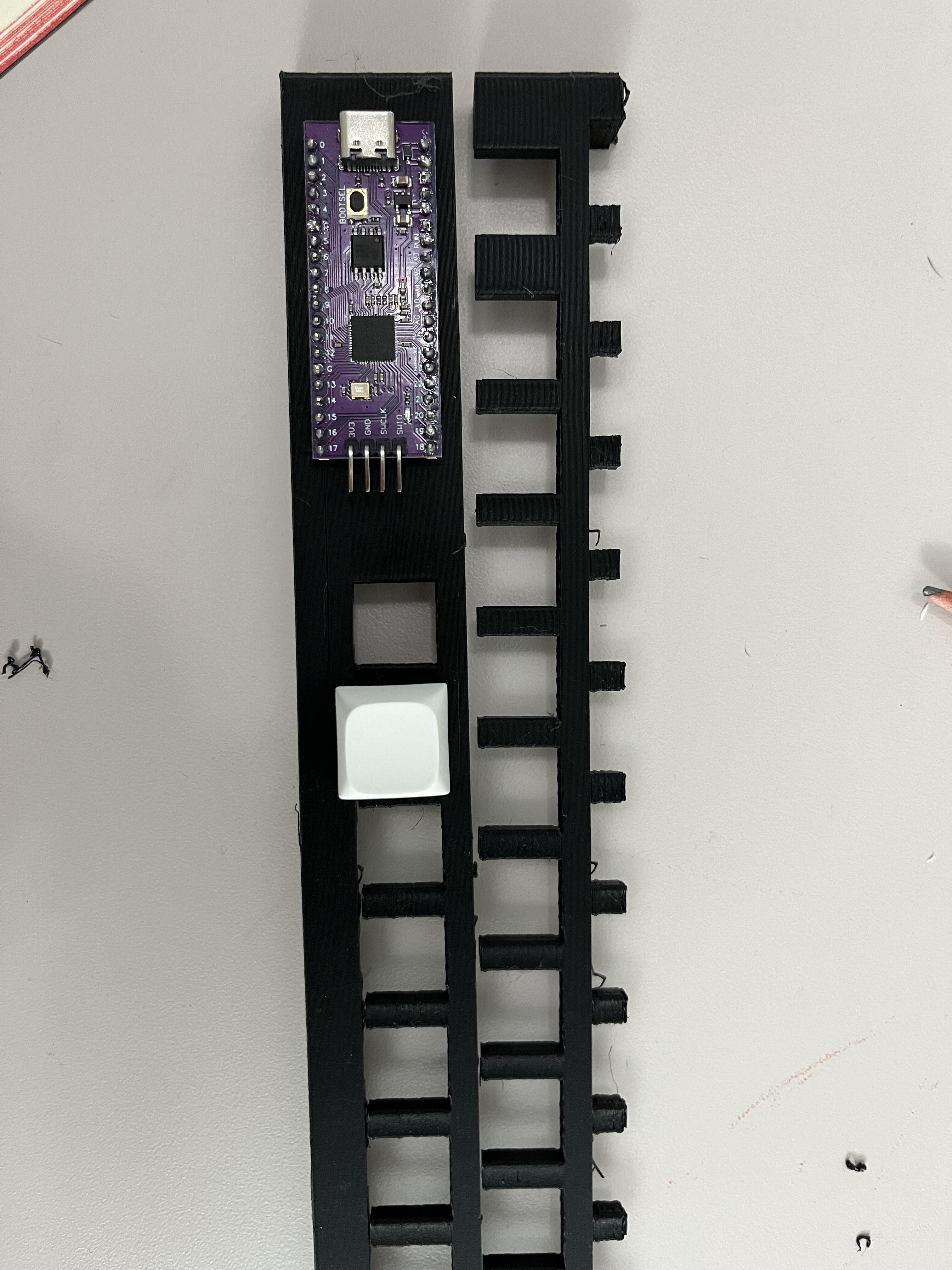
The new filament also had a snap (next couple of random prints will determine if this is something to troubleshoot more generally), but it got through a couple of rows first. Unfortunately, layer adhesion is what it is, and this solid print wasn’t much stronger than the hollow one. I think the design constraints I set for myself may have been too much for the material, and I’m doubting I’ll be able to make this design work as a single-piece print on a printer of this size, and frankly that was its only value-add compared to what is already out there.
On the plus side, whatever I go to next, I think I may revisit an idea from my first hand-wire (a Planck with an extra column of three keys, including a numpad enter) and go to a top mounted MCU. For a Masonite junkboard, that would save an entire layer of hardboard, so 3.2mm in thickness. I’ve also gotten a bit more experience with CAD stuff, which is always nice.
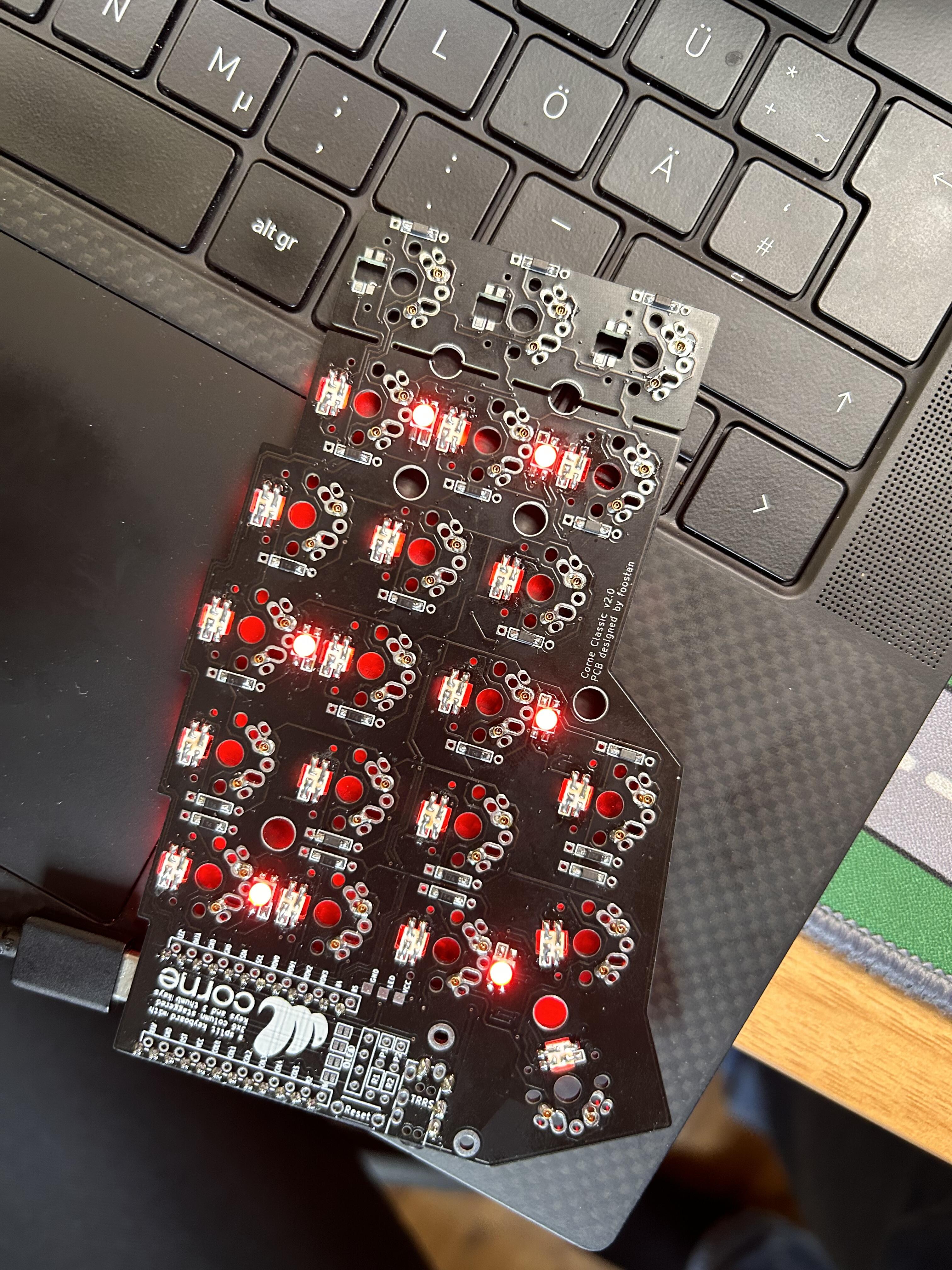
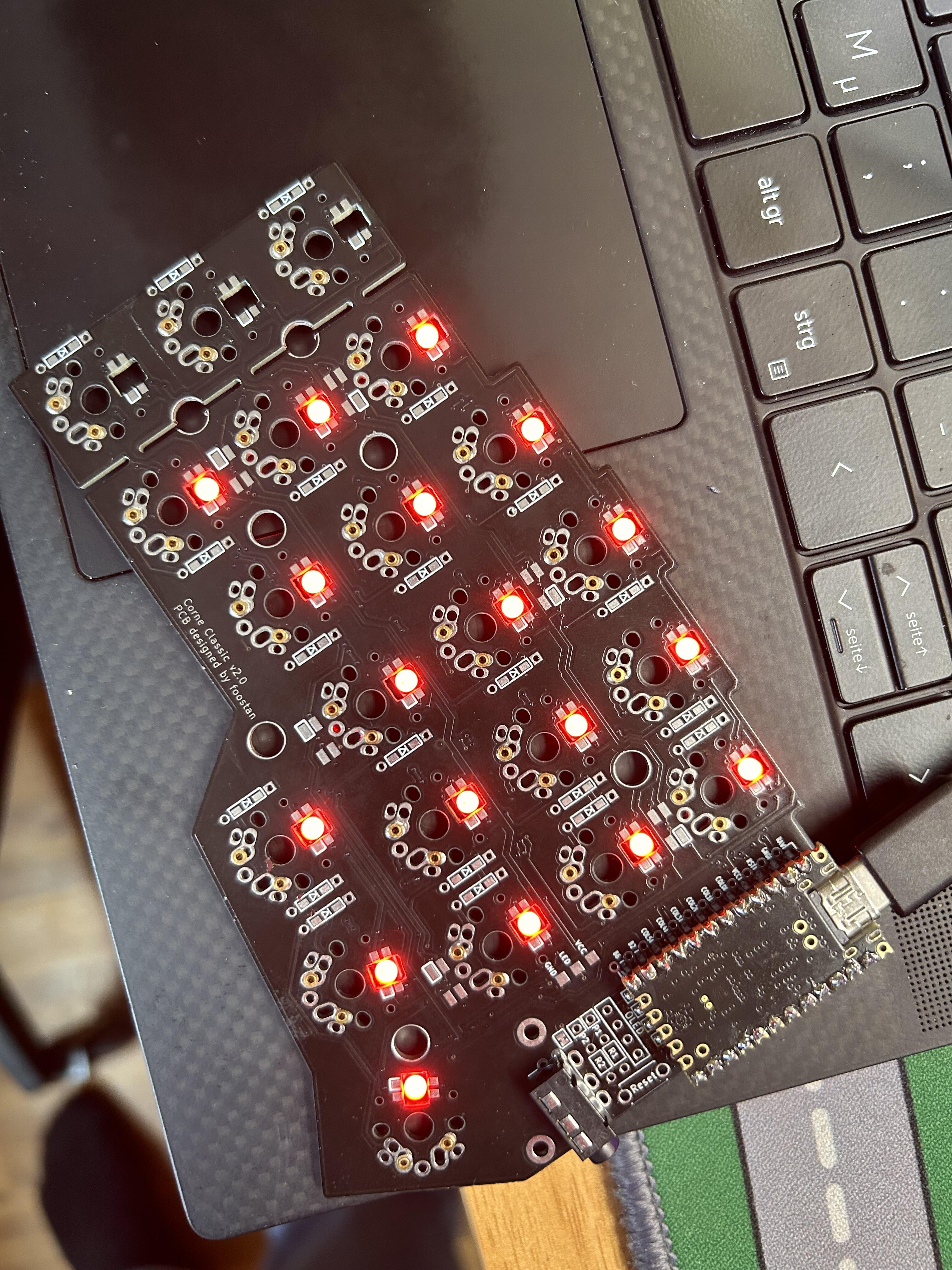
Sooo, I built my first Corne about 2 years ago. Was also my first project which included SMD soldering, and of course, I fucked up the RGB. So, first Corne got no RGB. Only some broken LEDs still stuck in that PCB. I then started to prepare the second set of PCBs last year, Millmaxed, SMD diodes (I hate THT diodes actually now) and I also started the RGB process again, with the leftover LEDs of the first project. While actually a bit better, still not very good. And I ran out of LEDs and the project paused.
I really wanted to finish that stuff now, so I chose to get a bunch of new LEDs and get it over with. Today I finished one whole side with completely new LEDs, which surprisingly worked almost immediately (after touching up 2 of the Underglow LEDs) and fixed the already started side. Tbh, fixing one missing pad of one of the Underglow LEDs by bridging the data in from the LED before was everything, but definitely not fun. However, I do now have to fully RGB Corne sides
I spare you pictures of the fixed up side, not pretty to look at and I actually didn’t take any
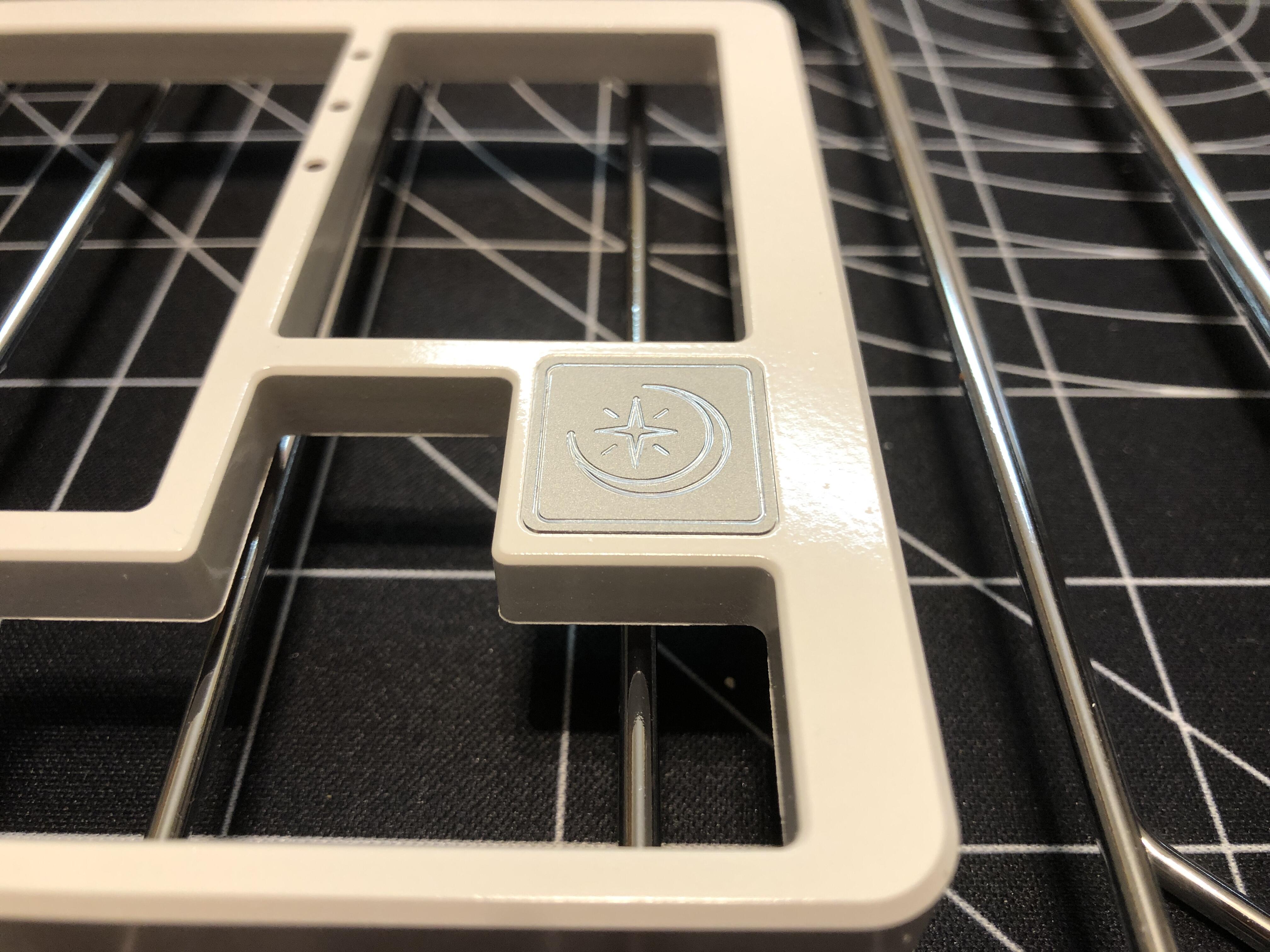
Not a perfect job, but not too bad for my first try! I’m kind of excited to try other stuff with it. I picked the finish because it’s supposed to be durable against oils once cured - I’ll let you know how that pans out in the long term, but it at least looks a little more solid than spraypaint.
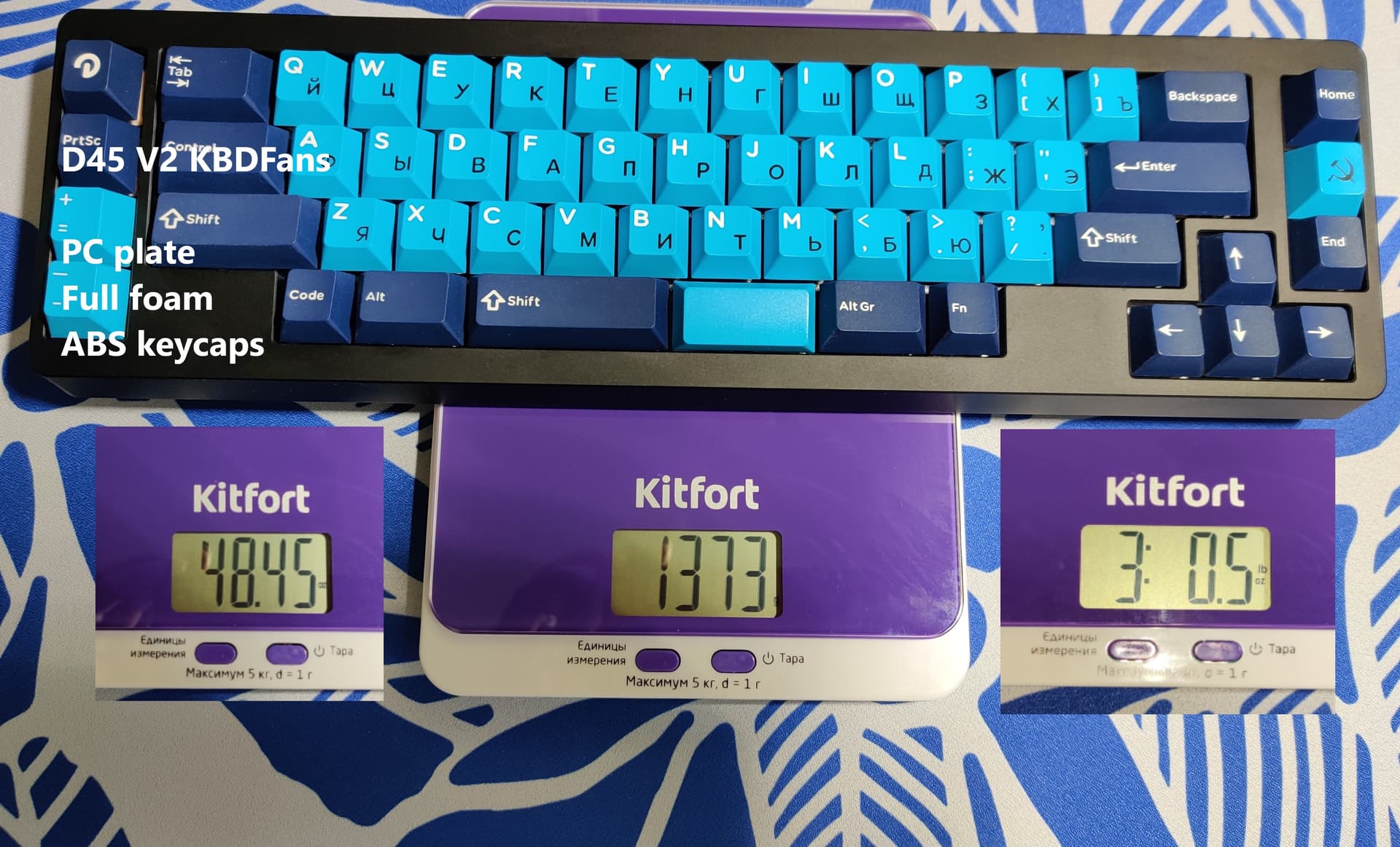
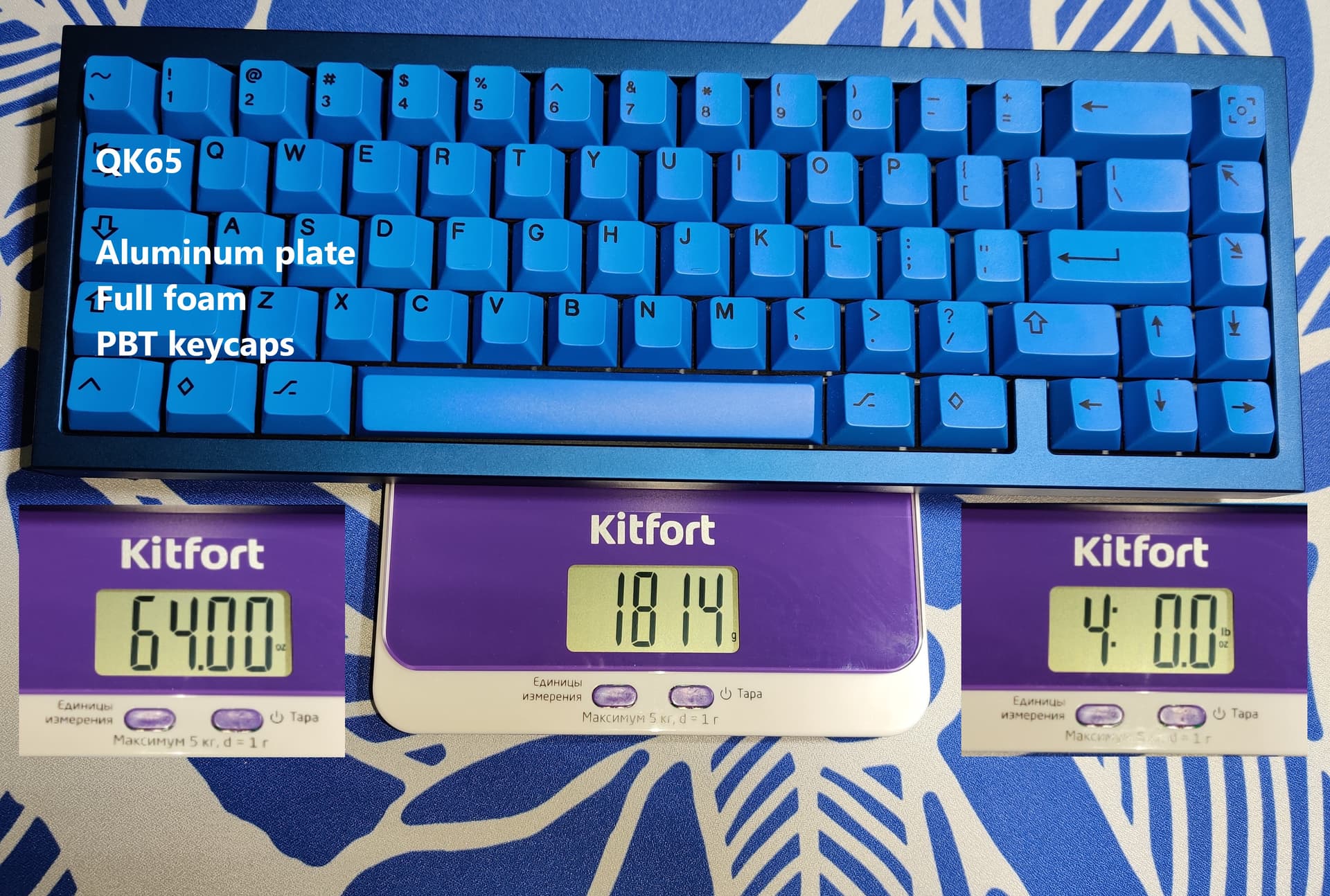
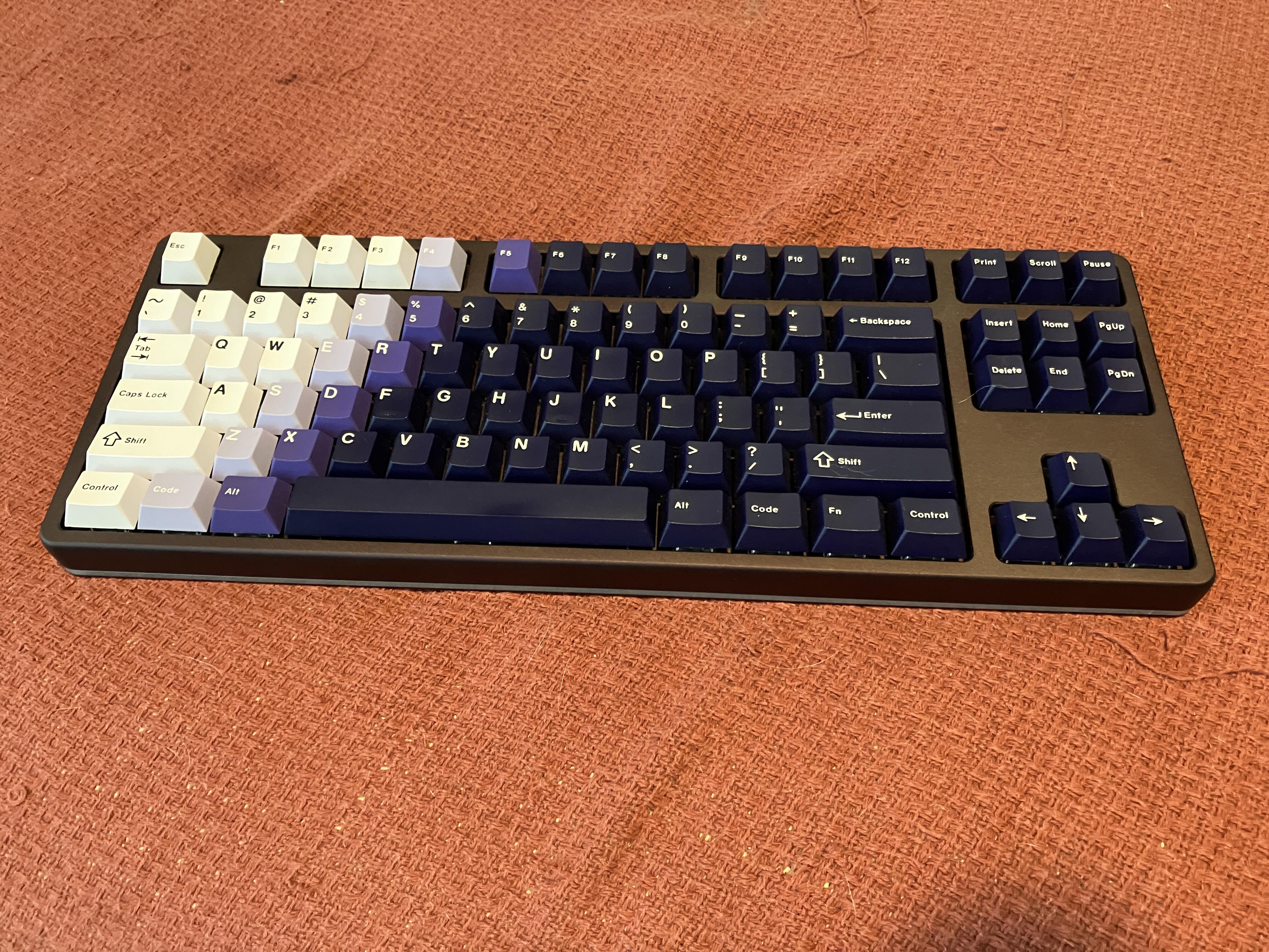
During assembly on an aluminum plate, I was convinced that this was a good case. It sits very firmly, rigidly, and snaps into the plate well, without any wobbles. I also chose ABS DROP DCX BLACK-ON-WHITE to better hear the sound when lightly tapping. And he’s not here. Well, when printing, after a lot of typing, I have not yet caught the effect that I felt on the first day. Very nice sound. Despite the fact that they are stock from the box.
So the first of two Model M’s arrived yesterday, the Terminal one. It was slightly less dirty than I imagined, and it is only missing four keycaps. I put together an internal Soarers, and it reads as an HID device after flashing in QMX tools, but I am getting absolutely nothing from the board, though 5v is getting to the keyboard from the converter, and I’ve tried flipping Data and Clock. Best I can tell, I wired everything up right.
I am stumped, but the medical board is coming tomorrow, and it is PS/2. Between the two of them, I’m only in for about $75. I will noodle on the issue for a bit, and maybe take the PS2 one apart (if it works) to see if the PCBs are pin compatible. If so, I will try to the PS2 cable on the Terminal board, and the converter on the Medical board, and try to do some trouble shooting.
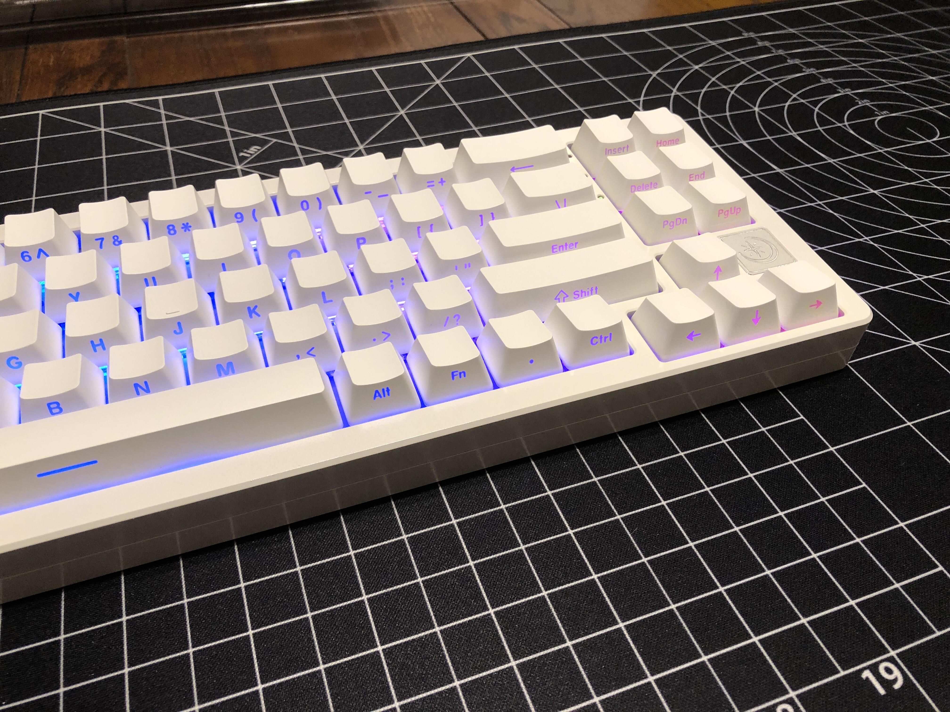
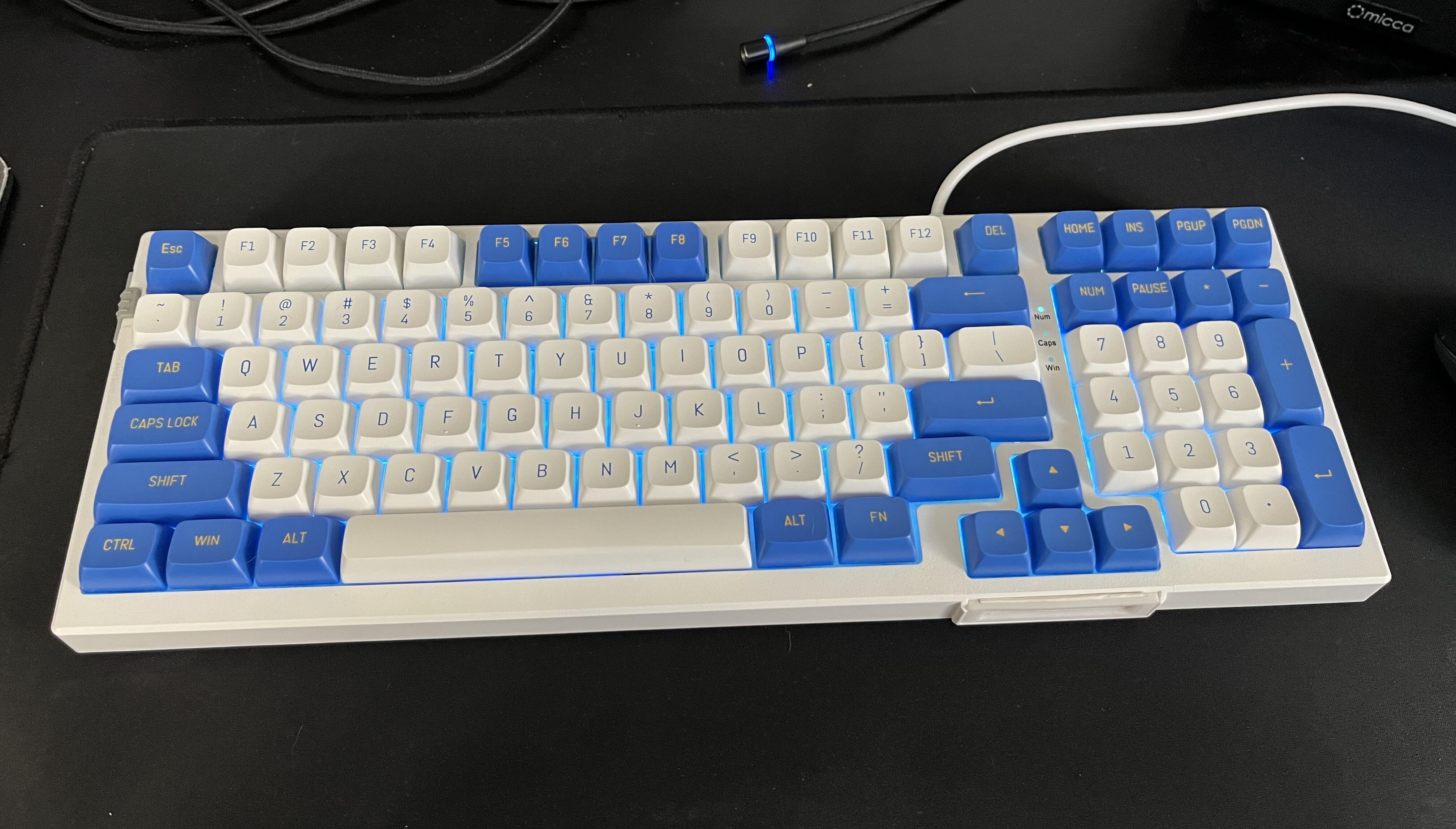
In the meantime, I grabbed an old pre-built and put some new keycaps on it, cheap “CSA” with Blue-on-White alphas and Yellow-on-Blue mods (annoyingly missing the numpad division key). This was literally the cheapest hotswap 1800 that I could find on Amazon a year ago, a Magegee. I pulled out the cheapo reds and replaced them with cheapo greens, and threw the kitchen sink of other cheap mods at it. There’s thin self-adhesive eva foam, a tape mod, and some random metal plates super glued inside it. I also threw away the name plate and did a 15 minute 3D print to make a frame that holds a little sliver of index card, currently reminding me of the media-key Fn combos I always forget. It is what it is, but it’s kinda nice. I did turn off the LEDs as soon as I took the picture though.
It’s more or less a preventative measure to make sure the edge of the wire doesn’t catch on the inside of the slider either from a rough cut of the wire, or an imperfection in the mould.
Removed the stabs from my Brutal v2, wiped out the gunk beneath and on the housings, cleaned up with some isopropyl, and relubed/applied dielectric. It felt good before in normal use, but I knew the truth.
Do people really desolder an entire keyboard to accomplish this, or do they just not have to because they’re better at tuning than me in the first place? I can get by for a long time with a careful job and a syringe, but eventually it seems inevitable. I’ve only had to on hotswap or plateless boards.
From my experience, not all dielectric grease is created equal. Permatex seems to be ubiquitous, but the amount of horror stories I have seen and heard of it separating and discoloring PCBs have kept me far away from using it.
I am a big fan of Loctite’s Dielectric grease and have never had an issue with it with it migrating or separating.
If you find that you are having to use a lot of lube or grease to quiet your stabilizers, it could also be that your wire isn’t completely flat or straight, or your PCB could also be slightly warped.
Barring that, you may also have to look into stabilizers specifically made for long-pole, or reduced travel switches.
These are just some of the main issues that seem to slowly be found less and less with newer stabilizers.
Thanks. I switched to Loctite as well on a friend’s recommendation. I agree that it seems to hold together much better than Permatex, though I still get it migrating down. Maybe I’m using too much.
Def a possibility, though they’ve seemed mostly straight. Usually they are TX or CK wires. I have the Geon bender tool and have tweaked a few but haven’t felt too great a need for it. Maybe I don’t know what I’m looking for (flat table/phone test and visual inspection). Is there a better way to judge straightness?
Def a possibility for the Skies, which are involved in the current issue. Unfortunately, I’m out of money for the moment :->
There are shims / washers that help with the long pole stuff, too - Upgrade Keyboards sells plastic ones for North-facing compatibility with Cherry caps but they also work great to adapt normal stabs for long pole switches. OLKB had metal ones first but they’ve been out of stock for years. More recently another vendor started selling stab-specific ones with the cross pattern in them - all three products work the same way, and I’ve found them very helpful.
Replying to myself. Great progress on the Soarer’s Converter. I started checking the tools that came in the zip, and actually looking into what was supposed to happen, and I realized mine was not identifying itself as a Soarer’s Converter. I further checked what it was supposed to look like when flashing, and I realized after some trial and error that the avrdude command in the QMX toolbox had not been working. It just said “flashed” but didn’t show progress. I downloaded a standalone copy of avrdude and copied the command from the toolbox, and lo and behold, the terminal board (mostly) worked! I had to track down a remapping “.sc” file to overlay on top of the main keymap, but now it’s working perfectly. I just need to clean the board up, acquire four replacement keycaps, and secure the converter in the case.
As an aside, I sort of forgot how honking huge these guys are, footprint wise. I run my WFH and personal PCs on the same desk, and I may need to go retrieve my trackball if I’m going to try that with a Model M. Not much room left. I can completely see why the earlier “mech renaissance” steel-plate Cherry MX (and clone) boards went with slim cases, often even floating-keycap “cases” under the plates. The M was meant to be your one and only input device, and it shows in the design language.
I was recently given some Cherry Clear Top Blacks, Kailh Heavy Yellows and Cherry Silent Blacks. The clear tops feel great but are a bit loud for my bare walled, echo-chamber office. One can hear my clacking all the way in the back of our building. The heavy yellows are pingy AF, I don’t like them but the weight is nice. Silent blacks feel scratchy and wobbly, love the sound though.
So, these are all on my desk today and I plan to swap parts around and find a good combo of weight, sound and feel. I will lube everything up as needed and report on progress.
If they fit loose in the plate you can use electrical tape on the edges of the cutout to “shim” the stabs in it tighter. Other than that, usual tuning rules apply the same to these IME.