Build #36: PC Norbaforce
The Norbaverse: Episode 3
Yes, episode 3. The Beach Norbatouch (build #16) and the Norbatouch Pi (build #19) were just early installments in the Norbaverse series, providing a little backstory for today’s episode. And once you’ve allowed yourself to rewrite history as you see fit, the door is wide open for build log possibilities. For example, this won’t even be the third @norbauer board I’ve built. There are others I have yet to incorporate into the Norbaverse (only Ryan’s order fulfillment database knows the full story - the rest of you will have to wait patiently). But with a soupçon of retcon, and a little warping of the space-time continuum, it’ll be no problem at all.
Back to our third installment. As always, I try to find waypoints in the journey that pass through new keyboard realms (for me, at least). When Ryan released the Ghost-of-Christmas-Future Edition polycarbonate Norbaforce Mark II, I saw a great opportunity for a quick tour through several parts of unexplored keebspace:
- Polycarbonate housings. Acrylic is the closest I’ve come so far, and I wanted to see how PC housings sounded and felt.
- The Realforce R2. I’ve had experience with Novatouch and Leopold boards, but not what is arguably the flagship of the current Topre lineup.
- The Norbaforce. I wasn’t in the hobby when this was initially released; Mark II was my first opportunity to work with this housing.
Ep 3 Act 1: Death of a Realforce
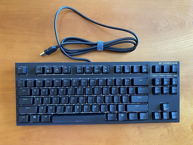
The donor board for this build is a Realforce R2 RGB TKL, for three reasons: it’s readily available, its MX-compatible sliders give us a much wider range of keycap choices, and its in-key RGB is tailor-made for use in a frosted polycarbonate housing.
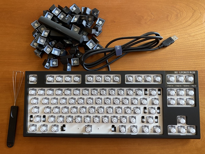
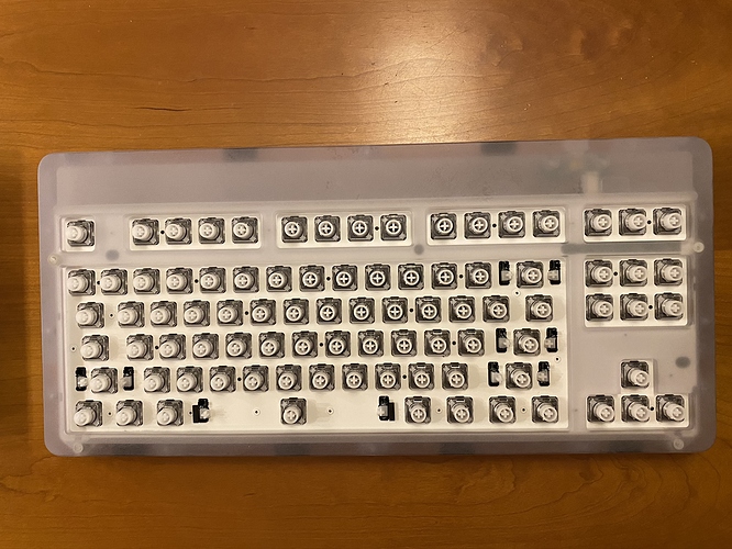
However, we’ll need to remove the original housing in order to transplant the PCB assembly into the Norbaforce housing. Before we start on that process, this is a good time to remove all of the stock keycaps. Have a look at all of those white MX sliders. Also, see that spring on the spacebar? If you plan to use it after modding, now is a great time to remove it and put it in a little Ziploc bag so you don’t lose it.
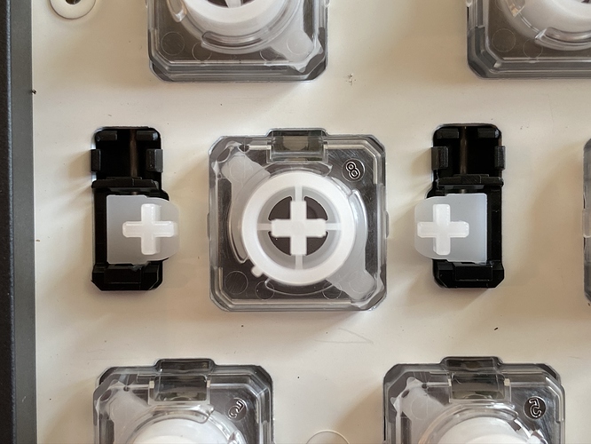
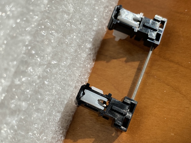
And while we’re here, take a look at the stabilizers in their natural state. The stabilizer housings appear to be clipped into the plate, and while the sliders look a bit different, they seem to function in the same way as a GMK clip-in stab, at least from this viewpoint.
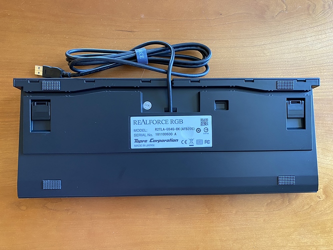
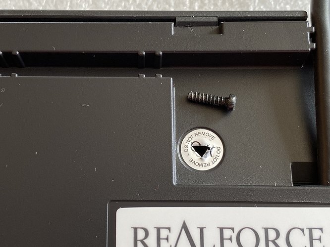
Flipping the board over, there are six tabs along the top edge which need to be pressed away from the body of the board to free the top edge of the base, and a screw that needs to be removed.
That screw lies underneath the little circular “O.K DO NOT REMOVE” sticker. Ready to void that warranty? You could carefully peel the sticker off, but I just went straight through with a Phillips screwdriver.
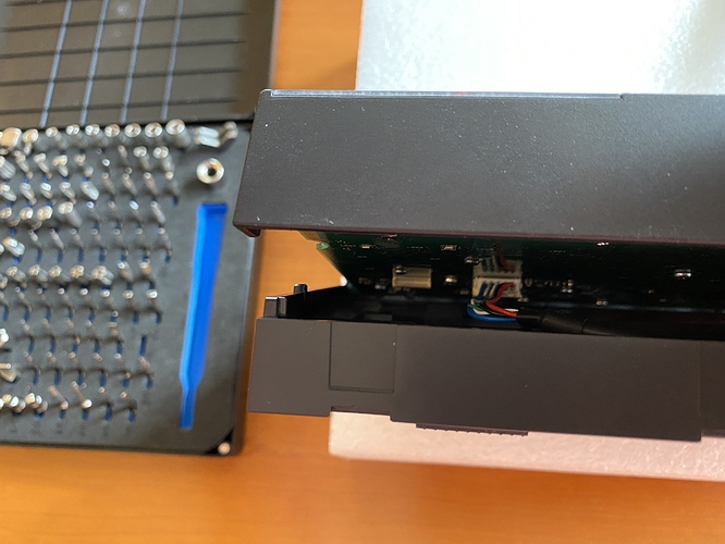
Before you start working on the bottom edge of the base, take a peek inside, and note that the Realforce USB cable is attached to the PCB by a connector. I might have been able to detach the connector at this stage, but I felt it would be easier to leave it attached and just exercise a bit more caution while removing the base, to avoid damaging the PCB.
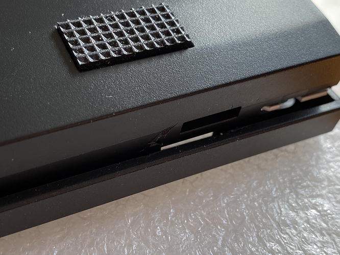
At this point, you need to separate the bottom housing from the top housing, along the bottom edge. The gap is narrow, but a credit card or small flathead screwdriver can be used to wedge them apart, and once you get one or two spots wedged apart, the rest will come apart a bit more easily. If you’re planning on reusing the stock housing, a credit card would be a better choice, as it’s likely to scuff up the case less than a flathead; I found it faster and easier to work with the flathead, and I wasn’t concerned about the original housing. Here you can see the two housing halves beginning to separate.
Now that we have the original housing removed, we can detach the PCB connector for the USB cable. Here’s a better look, right before we detach it.
The PCB/plate assembly, free of the housing:
Ep 3 Act 2: Bag of Bones
If the only thing you want to do is a housing swap, then feel free to skip ahead to the final act. But, if you’ve tried the Realforce R2 RGB TKL out of the box, you will know that this board has some rattle, to put it mildly. Like dropping a bag of skeletons down a mineshaft. It’s not really usable in its native state, and so we’ll have to do some extra work to make it usable.
If you’ve ever modded a Topre board, you know that two things are in your future: lots of screws, and lots of lube.
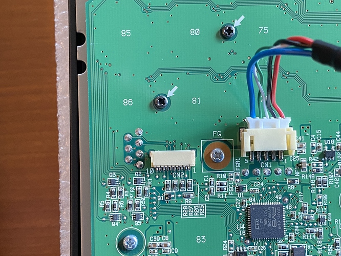
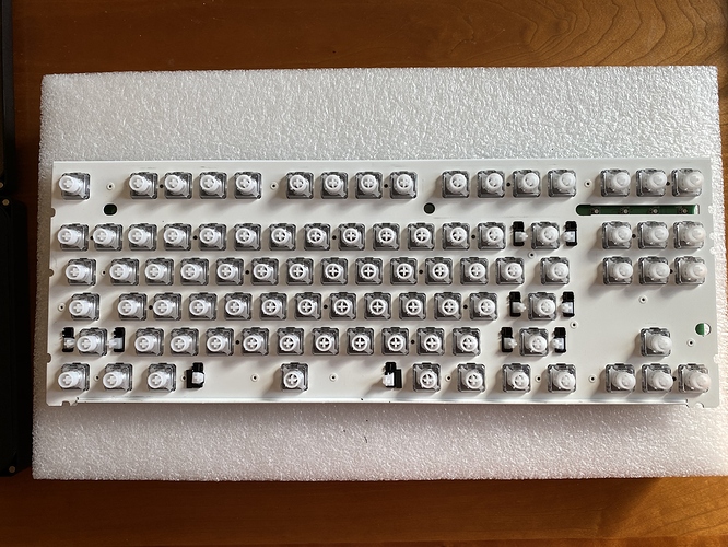
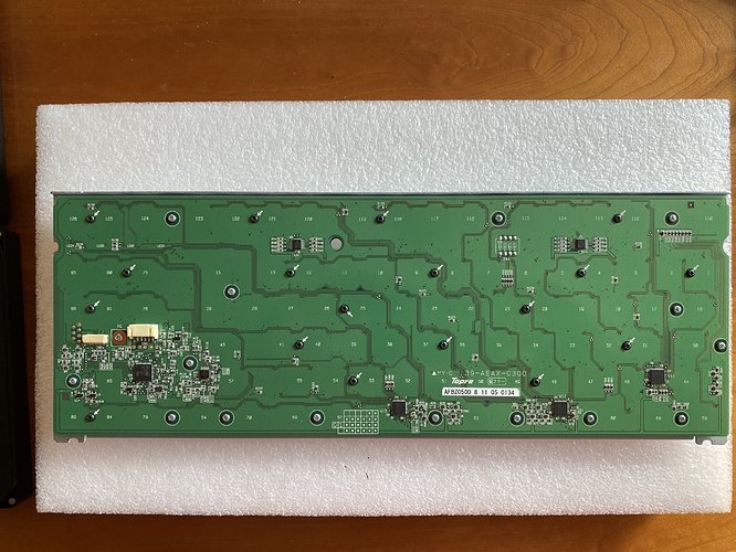
See all of those black screws, helpfully indicated by the white arrows on the PCB? See all of those silver screws, helpfully circled on the PCB? And that screw right next to the USB cable connector? All of these screws serve two purposes - to attach the plate to the PCB, and to apply even pressure for consistent electrocapacitive sensing on Topre PCBs. As a consequence, I offer two friendly notes of caution:
- Do not lose any of the screws as you remove them, or you may run into difficulty getting the board to function properly when you put it back together. A magnetic screw dish can be your best friend here.
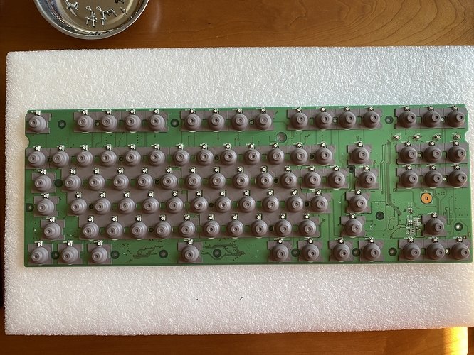
- On the other side of the PCB, there are rubber domes, and underneath those, conical springs, all of which are held in place solely by pressure. When the screws are removed, that pressure is gone. If you’re not planning on swapping in different rubber domes (and for this build, we’re not), then it’s worth trying your best not to disturb the existing domes, as realigning them is time-consuming, and the conical springs underneath are insanely light and want to fly everywhere if given a chance.
With those cautionary notes sounded, we are in the middle act of a three-act episode, so let’s go ahead and live dangerously. Drama! First, holding the PCB and plate together tightly (remember, no screws holding it together anymore!), we invert the assembly, and set it down gently.
Next, I’ve found that if you are exceedingly careful when lifting away the plate, there is often enough residual stickiness between the PCB and the rubber sheet to keep that sheet in place, exactly where you want it to be. And that turned out to be the case here - lifting the plate away cleanly, we see an undisturbed field of domes. We set this aside gently, out of the way of our working area, and out of the way of pets, kids, or any other instruments of destruction you keep around the house.
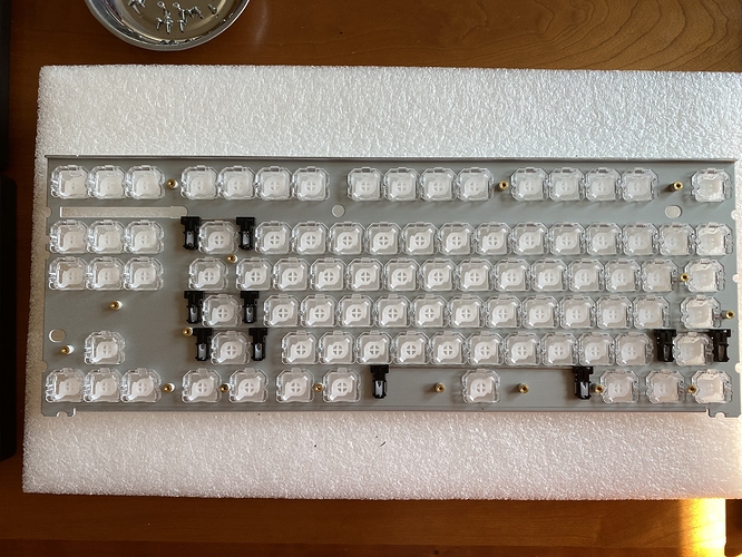
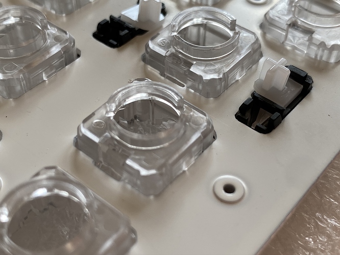
We can now take our first look at the underside of the plate assembly. Note that each slider has a little notch around its perimeter. At first I worried that there might be a specific orientation for each slider mounted into its housing, but it seems they’re just oriented one way or the other at random in each housing.
Removing the sliders is straightforward - just apply pressure from the top, and they’ll snap out. I found it easiest to do this with a fat hex bit on a screwdriver, just punching the sliders out; you can get all of them out in a couple of minutes.
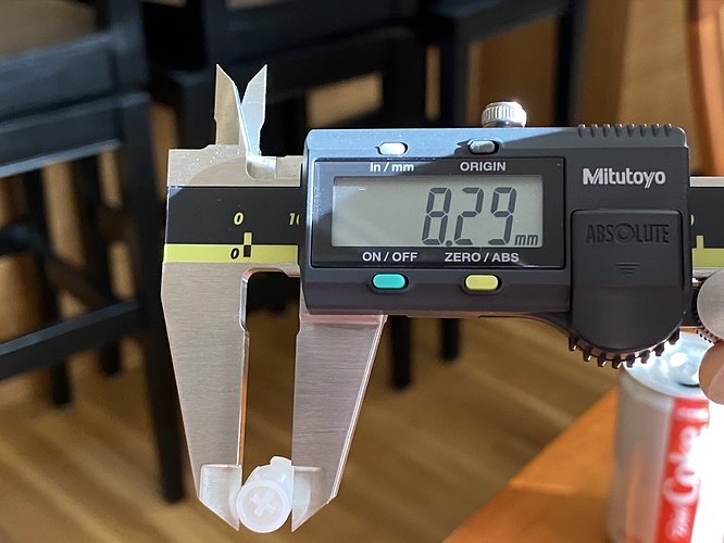
In a previous Norbaverse episode, we discussed variations in MX slider widths. For completeness, here’s the result for these new MX sliders - a bit narrower than the Novatouch sliders, but not as far off as the KBDfans sliders.
Once you’ve reached this point in the build, you’ll notice that the housings have an exceptional degree of rattle in the plate, and looking more closely at the perimeter of each housing, the tolerances aren’t exactly tight. To some extent this isn’t actually an issue; once the slider housings are under pressure again from the rubber domes beneath them, housing movement is significantly if not completely inhibited.
From that angle, we also have a good look at the clips for the stabilizer housings; you can easily pop them out by simply applying pressure with your fingers to the two black tabs on the front of the housing, pinching them inward while pressing down.
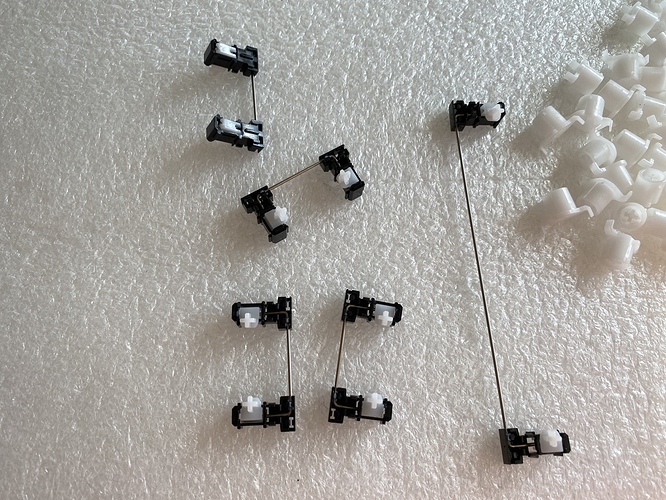
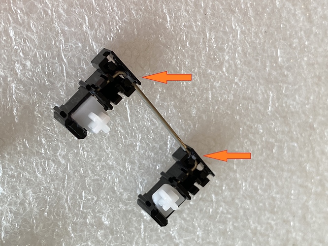
If these were GMK stabs, at this point I’d pop the wires out, remove the stab sliders, and lube in the usual way. But, these stabs are different. Right where you would expect a gap for the wire to pop out, these housings instead have what looks like a bit of molten plastic squirted into the gaps to hold the wire in place.
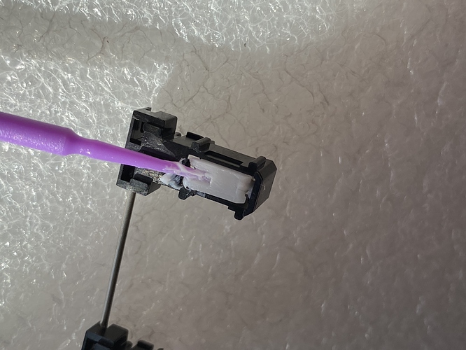
I considered just cutting through those bits, but I worried that the wire might just become too loose to be usable. So, instead, we’ll just leave the assembly in place, and apply as much lube as we can. We’ll start with the underside, in the gap where the wire inserts into the slider.
I’ve been finding that Christo-Lube works well on stabs, and is quite safe to apply in quantity on GMK stabs without worrying about introducing sluggish stab behavior, so I chose to use Christo 129 on these stabs. To get into that small gap in the slider, a dental applicator works reasonably well.
After that, it’s just a matter of filling the same spots from the top, and applying as much as you can where the wire meets the housing.
For the key sliders, the only spots that require lube are on the housings, where the sliders make contact with the housing. For this application, 3204 works well, and you can be a bit more liberal in your application than you would be with an MX-style switch, without adverse impact.
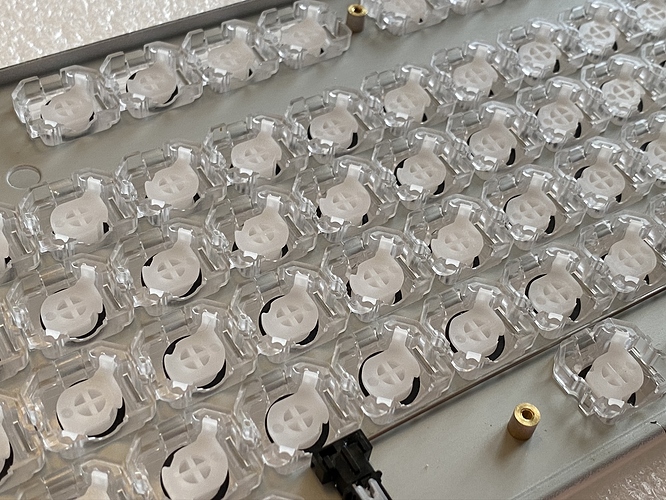
Finally, once you’ve lubed all those housing rails, you’ll want to apply silencing rings. In an unaired episode of the Norbaverse, I tried Deskeys #2 rings, but found them to provide insufficient silencing, so I went with the #3 rings for this build. Here we see all of the sliders with silencing rings applied, and snapped back into place.
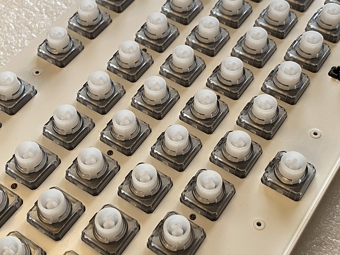
And, the view from the top. I’ve since become aware that Deskeys offers “RGB” versions of the rings with cutouts for the LEDs to shine through more cleanly, but as we’ll see later, not a big deal for this build.
From here, it’s just a matter of (gently) aligning and placing the plate back on top of the rubber domes and PCB, (gently) holding the plate and PCB together while inverting the entire assembly, and then getting all of those screws back in. At this point, it’s a very good idea to test that the PCB works, by reattaching the original Realforce USB cable and firing up a switch tester, before going further. In this case, all good on the first try. Happiness!
Ep 3 Act 3: Birth of a Norbaforce
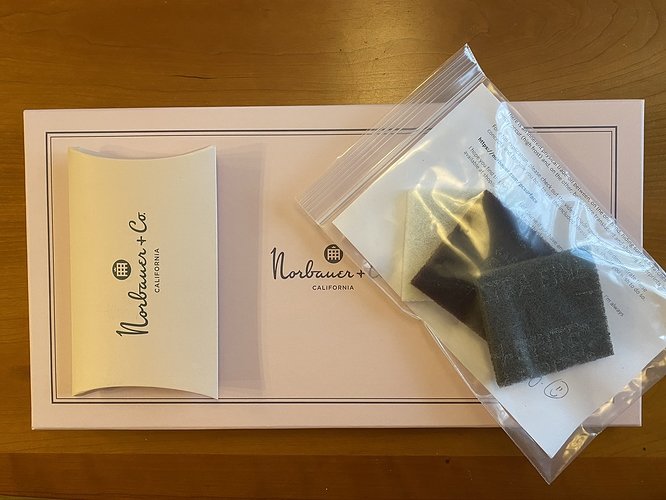
As usual, Norbauer’s packaging is premium - the Norbaforce housing comes in lovely well-padded packaging, additional parts come in a stylized branded sleeve, and the abrasive pads come in… wait a minute. Abrasive pads?
At this point, dive into a wormhole in the Norbaverse, and please allow Ryan to school you on the upkeep of frosted polycarbonate. I’ll wait for you to emerge on the other side.
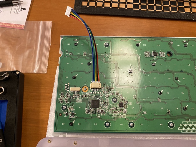
The Norbaforce Mark II uses a USB connector daughterboard, and a special cable to connect that daughterboard to the Realforce PCB. Our first step is to attach that cable to the PCB:
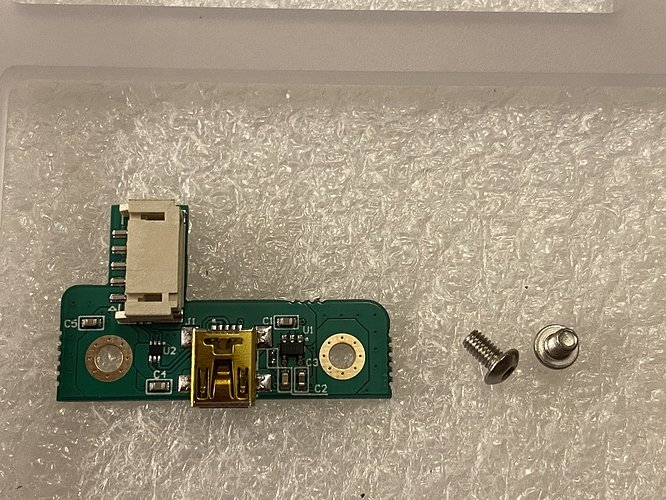
The daughterboard itself is a modest affair, which attaches to the Norbaforce housing with the included screws.
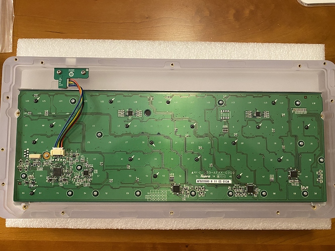
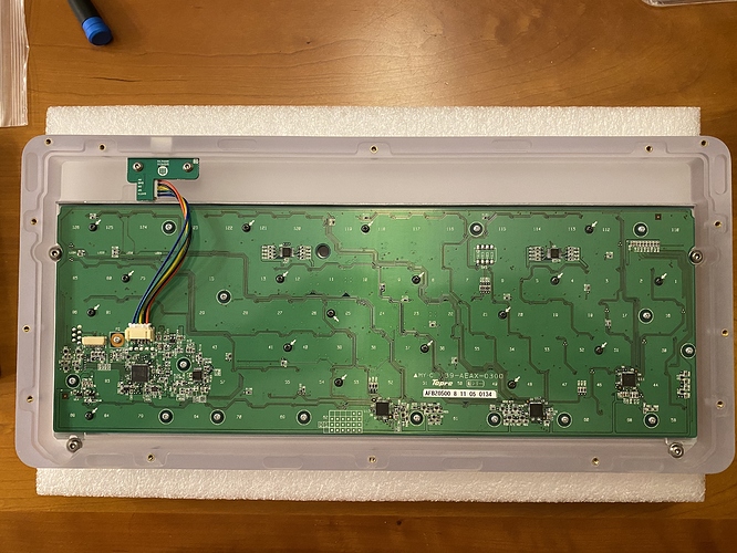
I found it easiest to first attach the other end of the cable to the daughterboard, and then screw the daughterboard into the Norbaforce base. We also get our first look at the PC housing, with a consistent frosted finish throughout.
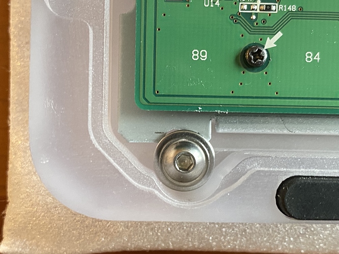
The PCB is then held in place by four more screws, although I found that the top two screws are doing the majority of the work, and getting those two aligned properly will lead to proper alignment of the PCB with the housing. The bottom two screws make minimal contact.
(One month after I wrote this build log, a comment from Ryan on the GB thread made me realize why there’s minimal contact - I didn’t use the included washers for the bottom two screws. Argh! After a quick bit of screwdriver work, here’s what a bottom mounting point should look like with the washer.)
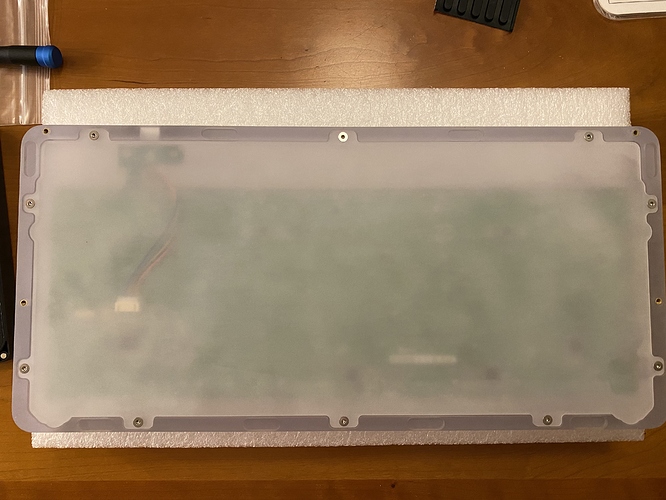
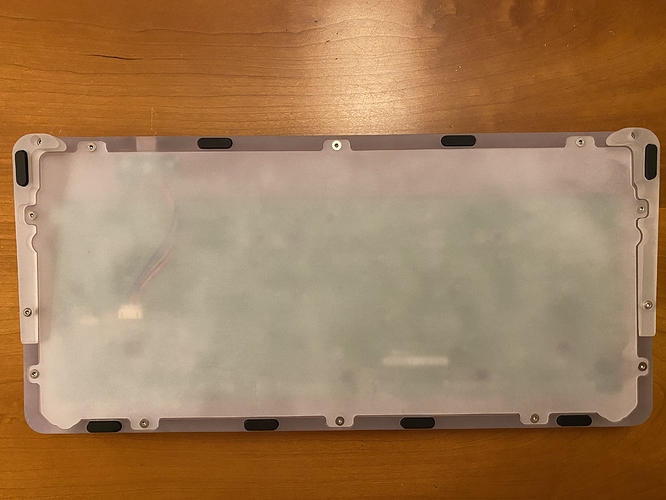
A comparatively thin piece of polycarbonate, with a more variable level of finish, screws to the back of the housing to close the underside of the case. The tolerance with respect to the PCB’s USB connector is quite tight; if you choose to put shelf liner or foam in the case, you would need to make a cutout for this connector for the liner to fit cleanly in the case.
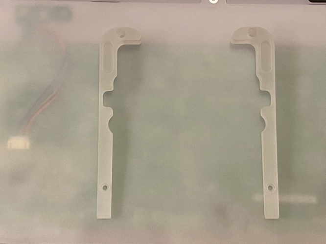
I like some tilt to my boards, so we’ll install the included risers for the Norbaforce. Pre-installation:
The risers simply screw into place on either side of the case. Note that if you plan to use the included bumpons on the Norbaforce, you need to first decide whether you are going to use risers. I had applied bumpons before I put the risers on, when I discovered that the risers won’t actually install with a bumpon underneath them - so I had to peel those two bumpons out of their cutouts on the bottom housings, install the risers, and then place them again, this time on the cutouts on the risers. Sigh. That’s also why you see the two bumpons at the top of the case, which will make contact with absolutely nothing when the risers are installed. Don’t be like me - inspect the components first!
Getting close now - here’s our first look at the top of the PC Norbaforce.
Remember that spacebar spring, that I told you to put into a Ziploc bag? Now’s the time to put it back in place.
Or not. Even after all the lube, I still had some spacebar rattle. Part of that was addressed by shoving even more 129 into the stab housings, but the other part was addressed by removing this spacebar spring. YMMV, but it seems to do essentially nothing as far as I’m concerned.
After downloading the Realforce software and configuring the board, it’s Thock Time. I was worried that the PC housing might sound a bit hollow, and it does, if the board is placed directly on a hard surface - but on a deskmat, it’s fine. I’m also pleased to report that the abrasive pads work as advertised; I was able to buff out a patch on the Norbaforce forehead to bring it back to a nice level of frost. Take it easy, though - you are definitely removing material with the most abrasive pad of the bunch.
Lessons learned
- If we’re trying to convince a person new to the hobby that lubing is essential for a premium experience, I’m beginning to think a Topre board makes the best argument for that proposition. The before/after difference in sound is amazing, and the actual lubing is significantly less time consuming for Topre than it is for a batch of MX switches, even allowing for the extra lube that has to be shoved into Topre stabs. No rattle, and smooth, deep thock.
- Deskeys #3 rings are doing more than the #2 rings to silence the board, for sure - but I think I could be happy going even further. I’ll have to try #4 and #5 rings soon.
- Along with Christo 111, which I’ve used with success on GMK stabs, Christo 129 works well for these stabilizers, and is a cheap lubricant - which is good, because you’re going to need much more of it for those Realforce R2 stabs. Yikes.
- If you’re not dome swapping your Topre board, it’s possible to leave the domes and springs in place and save a lot of build time - but it requires that you have your wits about you.
- The modest additional force the Realforce spacebar spring provides may not be worth the spacebar rattle it introduces, and it can be left out with no adverse effects.
- I wasn’t sure I’d necessarily like PC as a housing material, but the sound of this board is making me curious to try it again with MX-style switches.
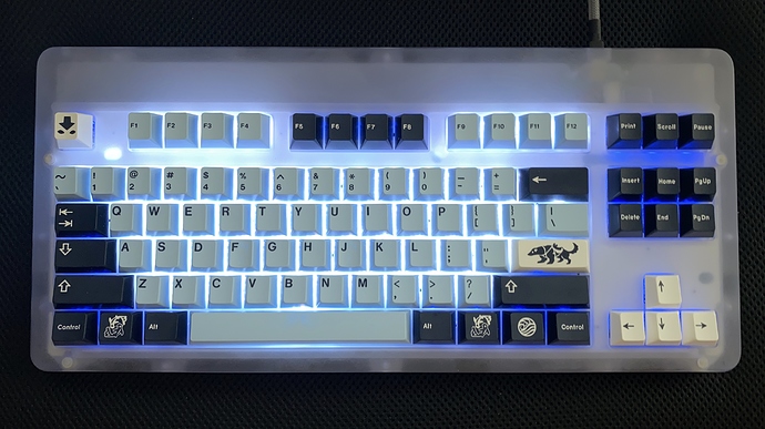
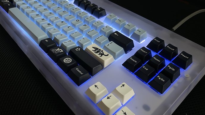
This board was advertised as the “Ghost-of-Christmas-Future”, and I considered going for a holiday look when matching keycaps, but after seeing the RGB in action, I had to go with a luminous block of ice, and the shades of blue that implied. Or perhaps it’s Cerenkov radiation. A Christmas Carol redux, a frozen wasteland, or an exposed nuclear core? Choose your future Norbaverse.
Specifications
donor board: Realforce R2 RGB TKL
case: "Ghost-of-Christmas-Future Edition" polycarbonate Norbaforce Mark II
case dampening: n/a
PCB: donor
plate: donor
plate/PCB dampening: n/a
LEDs: per-key RGB in donor PCB
switches: stock Topre domes (45g)
switch mods:
- Tribosys 3204 on slider housing rails
- Deskeys #3 silencing rings on sliders
- removed Realforce spacebar spring
stabilizers: donor
stabilizer mods: Christo MCG 129 on all wire-housing contact points
keycaps: GMK Mizu (base, novelties)
HxWxD (without feet, risers, or caps): 0.88" x 15.13" x 7.13"
HxWxD (without caps): 1.25" x 15.13" x 7.13"
HxWxD: 1.63" x 15.13" x 7.13"
assembled weight: 1.26 kg (2.77 lb)
